Concoa MEDICAL INTELLISWITCH 571 Series User manual

ADI 9513-D
571 SERIES
MEDICAL INTELLISWITCH
Web Server
INSTALLATION AND USER’S GUIDE
Carefully Read These Instructions Before Operating
Carefully Read These
Controls Corporation of America
1501 Harpers Road • Virginia Beach, VA 23454
Telephone 1-800-225-0473 or 757-422-8330 • Fax 757-422-3125
www.concoa.com
November 2015
Revision D


i
Index
What You Need....................................................................................................................1
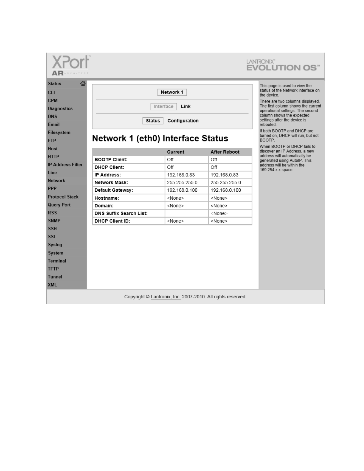
Connecting the Web Server.................................................................................................1
Gaining Access to the Web Server ......................................................................................8
Using the Web Server..........................................................................................................8
Features..........................................................................................................................8
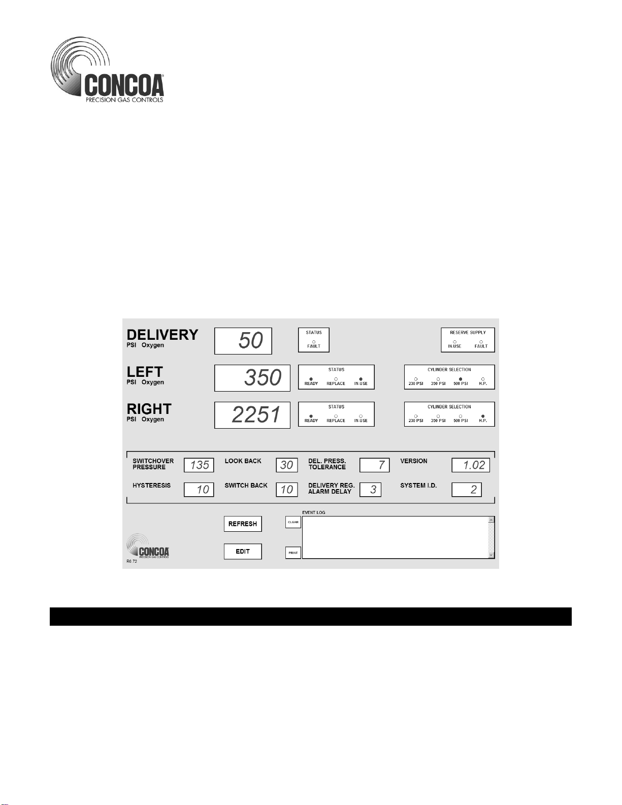
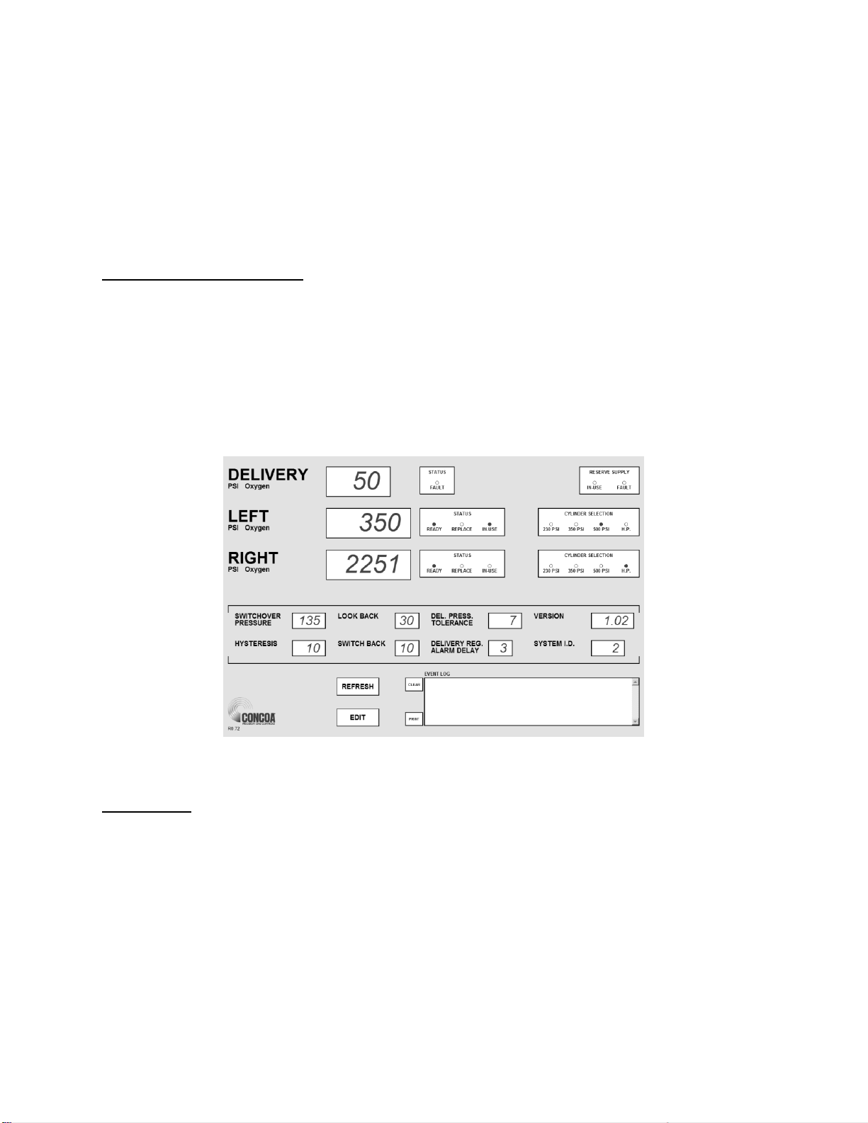
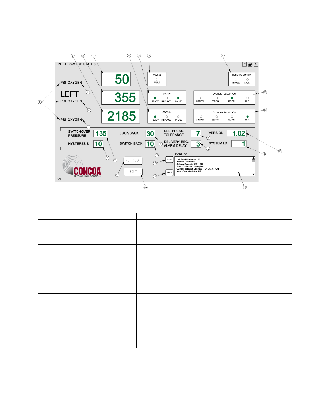
STATUS Screen.............................................................................................................9
EVENT LOG...............................................................................................................11
EDIT SCREEN............................................................................................................12
Password................................................................................................................12
Modifying a Parameter ..........................................................................................15
EMAILING..................................................................................................................18
EMAIL1.................................................................................................................18
EMAIL2.................................................................................................................20
EMAIL CONFIGURATION.................................................................................23
Configuration Data.............................................................................................................26
Warranty Information ........................................................................................................27
Tables
Table 1 STATUS screen functional descriptions.................................................................9
Table 2 EDIT screen functional descriptions.....................................................................13
Table 3 EMAIL1 screen functional description.................................................................19
Table 4 EMAIL2 screen functional description.................................................................21
Table 5 EMAIL CONFIGURATION................................................................................23
Table 6 TROUIBLE SHOOTING GUIDE........................................................................24

1
WHAT YOU NEED
Computer: Pentium 4 or better
Monitor: Capable of MINIMUM display resolution 1024 x 768
Operating System: Microsoft Windows XP, XP Professional, Vista
Local Area Network Connection
Internet Browser: Internet Explorer, Mozilla FireFox
The installation and setup for the IntelliSwitch Web Server (IWS) must be performed by a person with a
working knowledge of the internet, local area networks and computers, such as a LAN Administrator.
CONNECTING WEB SERVER
CONCOA strongly suggests that this device be placed behind a firewall. Is it not suitable for public
internet access.
The IWS is designed to communicate via a local area network connection. Power to the IntelliSwitch
should be OFF. Connect the IWS to the network via an RJ-45 network cable. The RJ-45 connection
on the IntelliSwitch is located on the bottom of the IntelliSwitch. It may be necessary to remove the
protective cover to access the RJ-45 connection on the IntelliSwitch.
The IWS is configured with the following default network settings:
IP Address: 192.168.0.83
Default Gateway: 192.168.0.100
To change the network settings connect to the IWS use the following procedure:
Using either Internet Explorer or Firefox and the newly assigned IP address (192.168.0.83), enter
the following in the address box at the top of the screen:
http://192.168.0.83/config/config.html.
Username: admin
Password: PASS
If connected properly, an image similar to the one in Figure 1 below should appear on your screen.

2
Figure
1
In the orange column on the left locate the word “Network” and click on it. The image in Figure 2
should appear.

3
Figure
2
Locate the word configuration at the top of the screen and click on it. Figure 3 should appear.

4
Figure
3
Update the fields on the configuration with the desired network settings and click “Submit.” Make sure
you cycle power on the unit before attempting to connect using the new network settings.

8
GAINING ACCESS TO THE WEB SERVER
Using either Internet Explorer or Firefox and the newly assigned IP address (xxx.xxx.x.xxx),enter the
following in the address box at the top of the screen:
http://xxx.xxx.x.xxx/intelliswitch/status.html.
If connected properly, an image similar to the one in Figure 4 below should appear on your screen.
ADDING IWS TO DESKTOP
For convenience the IWS should be added to your favorites and/or your desk top. To do this, reduce the
IWS image using the “Restore Down” icon in the upper right corner of the screen so that it only occupies
a portion of your desktop. Next, open up favorites and find your new entry for the IWS and drag it over
to the desk top. You may wish to rename the icon so that it has a name that is easily recognized for the
device being used. The IWS is now ready to use. Refer to the section “USING THE WEB SERVER” to
learn what functions it has and how to use it.
Figure 4
USING THE WEB SERVER
FEATURES:
The IWS has a number of useful features. The STATUS screen is what appears when the IWS is first
accessed. This screen provides the ability to monitor a number of parameters as well as providing an
“event log” that allows viewing of IntelliSwitch activity. Clicking on the EDIT button will bring the user
to the EDIT screen. Here it is possible to change various parameters within the IntelliSwitch. Also on the
EDIT screen are two buttons marked EMAIL1 & EMAIL2. Clicking on one of these buttons will bring
the user to an EMAIL setup screen. The IWS has the capability of emailing any activity that may occur
while the IntelliSwitch is in use. Each screen and its function will be explained in subsequent pages of
the manual.

9
STATUS SCREEN
Figure 5
Table 1 that follows provides a description of each of the parameters on the screen (Figure 5)
Table 1
Bullet
Item
Description
1
Delivery Display
Displays the Delivery Regulator Pressure
1A
Delivery Regulator Status
Indicates if the left delivery regulator is in use or if it has a fault.
In-use radio button will light green and fault radio button will light
red if a fault occurs
2
Left Inlet Pressure
Displays the Left Inlet Pressure
2A
Left Inlet Status
Radio buttons display the current status of the left inlet gas
supply. Green Ready indicates that there is enough gas on the
left side so it can be used. Green In-Use indicates that the left
side is being used. Red Replace indicates that the gas supply
on the left side needs to be replaced.
2B
Cylinder Selection
Radio buttons indicate what type of cylinder selection is made
for the left inlet. Green indicates which cylinder type is selected
3
Right Inlet Pressure
Displays the Right Inlet Pressure
3A
Right Inlet Status
Radio buttons display the current status of the right inlet gas
supply. Green Ready indicates that there is enough gas on the
right side so it can be used. Green In-Use indicates that the
right side is being used. Red Replace indicates that the right
side needs to be replaced.
3B
Cylinder Selection
Radio buttons indicate what type of cylinder selection is made
for the right inlet. Green indicates which cylinder type is
selected

10
Table 1 (cont.)
Bullet
Item
Description
4
Units of Measure
Choices are PSI, BAR and MPA. Pressures will be displayed in
the units shown in this area.
5
GAS Type
Displays the gas type the IntelliSwitch is controlling. This is set
by the user from the EDIT screen.
6
Reserve Supply Status
If the product is equipped with a Reserve Gas Source the status
of that source will be displayed here. Green In-Use indicates
that the IntelliSwitch is using this source. A Red Fault indicates
that the reserve supply is low on gas and needs to be replaced.
It is possible to have the Reserve in-use and have a fault. This
would occur if both the left and right inlets are also in replace.
7
Switchover Pressure
This is a preset pressure in the IntelliSwitch used to determine
when an inlet can no longer provide enough gas pressure to the
delivery regulator. This value can be changed in the EDIT
screen.
8
Hysteresis
This is a preset pressure value that is used to prevent the
IntelliSwitch from “dithering” at the switchover point.
9
Look Back
This is a preset time in minutes used for liquid cylinders to
determine when to look back at an inlet pressure to determine if
pressure has been restored above the switchover point. The
IntelliSwitch will look back at an inlet after the look back time has
expired to see if its pressure has built back up above the
switchover point. If it has, then the IntelliSwitch will switch back
to that side to try to use more of the gas.
10
Switch back
A preset time in minutes used for liquid cylinders in conjunction
with the look back time. If the look back feature is invoked and
after time out has determine that it can switch back to a side
whose pressure has built back, a switch back timer will start. If
the inlet pressure on the same side drops again before the
switchback time has expired the IntelliSwitch determines that
that side is truly empty and will alarm and switch to the other
inlet.
11
Delivery Pressure Tolerance
This is the variation in delivery regulator pressure that is allowed
before the IntelliSwitch switches regulators and alarms. The
value is +/- the pressure shown.
12
Delivery Regulator Alarm
Delay
This is the amount of time, in seconds, that the IntelliSwitch will
wait before switching delivery regulators or alarming. This
prevents false switching and alarming if the delivery regulator
pressure should increase or decrease from its nominal value
beyond the delivery regulator tolerance for a very brief time.
13
Version
this is the software version of the IntelliSwitch software on your
system
14
System ID
This is a number that can be assigned by the user to identify the
IntelliSwitch.
15
REFRESH button
Clicking on this button will force an immediate display update.
Normally the IWS updates the display approximately every 4-5
minutes unless an “event” occurs. An “event” is defined as an
alarm or any activity such as pressing a button that causes
switching or a change in cylinder selection
16
EVENT LOG
This is a location used to list any events that may occur
17
CLEAR button
This button clears the contents of the event log
18
PRINT button
This button allows the printing of the contents of the event log to
a users computer
19
EDIT button
Clicking this button will bring the user to the EDIT screen where
changes to parameters can be made. The EDIT screen is
password protected

11
EVENT LOG
The Event Log provides a record of any events that may occur while the IntelliSwitch is running. This
can be an alarm condition or a key press. Essentially, any “event” that may occur either as a result of a
response to a change in conditions or operator intervention. A list of “events” that could be displayed in
the event log is shown below.
Inlet Value Status –“description”
Error –“description”
Left Side O/P –“value” (O/P = over pressure)
Right Side O/P –“value”
Reserve Alarm
Left Side U/P –“value” (U/P = under pressure)
Right Side U/P –“value”
Reserve In-Use
Keypad Lock “description”
Cylinder Selection Changed –“description”
Delivery Regulator O/P –“value”
Delivery Regulator U/P –“value”
Delivery Regulator Status –“value”
Reserve Status –“value”
Alarm Clear U/P Left Side –“value”
Alarm Clear O/P Left Side –“value”
Alarm Clear U/P Right Side –“value”
Alarm Clear O/P Right Side –“value”
Alarm Clear Reserve Gas
The word “value” is replaced by a pressure in psi. The word “description” is replaced with and
explanation of what happened.
The Event Log can store up to 50 events. Once the quantity of events reaches 50 it will continue to list
the events but push events off the list starting with the first one. The list will be maintained until it is
cleared. To clear the Event Log, click on the “CLEAR” button.
The Event Log can also be printed if a permanent record is needed. The PRINT function can use
whatever printer the user’s computer is connected to. To print the event log, click on the PRINT button.
A normal windows print screen will appear.

12
EDIT SCREEN
The EDIT screen allows the user access to the IntelliSwitch operating parameters as well as EMAIL
options. This screen is password protected. The password is fixed and cannot be changed. To enter the
EDIT screen, click on the EDIT button at the bottom of the STATUS screen. The Password pop-up ,
Figure 6, will appear. Click in the blank text box and type: 19490321. Now either click on “OK” or
press ENTER on the keyboard. The EDIT screen will appear (Figure 7).
Figure 6
Figure 7
The upper portion of the EDIT screen (Items 1 –15) displays the parameters that can be modified
individually and directly. The lower portion of the screen contains various buttons that invoke various
functions. The SET button (Item 16) is used to transfer the parameters on the EDIT screen to the

13
IntelliSwitch. This gives the user an opportunity to review and/or modify any value before the parameters
are permanently changed. The other buttons will be explained further along in this manual.
Pop-up messages are used throughout this screen to aid in setting parameters. Items 1-10 and buttons
“ZERO SET”, and “RESTORE DEFAULTS” have associated pop-up messages that will appear when the
mouse pointer is over them. The “SET” button and “UNDO” buttons will show pop-up messages after
they have been selected. Use these messages as guides to correctly set values on this screen.
Figure 7 and Table 2 describe the various parameters on the screen.
Table 2
Bullet
Item
Description
1
Switchover Pressure
This is a preset pressure in the IntelliSwitch used to determine
when an inlet can no longer provide enough gas pressure to the
delivery regulator. Data range: 50-500psi
2
Look Back
This is a preset time in minutes used for liquid cylinders to
determine when to look back at an inlet pressure to determine if
pressure has been restored above the switchover point. The
IntelliSwitch will look back at an inlet after the look back time has
expired to see if its pressure has built back up above the
switchover point. If it has, then the IntelliSwitch will switch back to
that side to try to use more of the gas. Data range: 10-60 min.
3
Switch back
A preset time in minutes used for liquid cylinders in conjunction
with the look back time. If the look back feature is invoked and
after time out has determine that it can switch back to a side
whose pressure has built back, a switch back timer will start. If the
inlet pressure on the same side drops again before the switchback
time has expired the IntelliSwitch determines that that side is truly
empty and will alarm and switch to the other inlet. Data range: 10-
60 min.
4
Hysteresis
This is a preset pressure value that is used to prevent the
IntelliSwitch from “dithering” at the switchover point. Data range:
10-50 psi.
5
Left Offset
This is a value that can be used to adjust the pressure transducer
reading for the left inlet. This value should only be changed if it is
necessary to recalibrate the transducer. Changing this value will
change the left inlet pressure reading. A (+) or (-) value may be
entered here. Refer to “Calibrating Transducers” section of the
IntelliSwitch user’s manual. Data range: +/- 200 psi.
6
Right Offset
This is a value that can be used to adjust the pressure transducer
reading for the right inlet. This value should only be changed if it
is necessary to recalibrate the transducer. Changing this value
will change the right inlet pressure reading. A (+) or (-) value may
be entered here. Refer to “Calibrating Transducers” section of the
IntelliSwitch users manual. Data range: +/- 200 psi.
7
System ID
This is a number that can be assigned by the user to identify the
IntelliSwitch. Data range: 1-254.
8
GAS Type
Displays the gas type the IntelliSwitch is controlling. The pop-up
message will show the choices. The choices for gas type are
numbered. Enter the number next to the gas type in the text box.
The name of the gas will appear on the status screen next to units
of measure Data range:1-99 (refer to pop-up message for details)
9
Delivery Pressure
Tolerance
This is the variation in delivery regulator pressure that is allowed
before the IntelliSwitch switches regulators and alarms. The value
is +/- the pressure shown. Data range: 5-15psi.

14
Table 2 (cont.)
Bullet
Item
Description
10
Delivery Regulator Alarm
Delay
This is the amount of time, in seconds, that the IntelliSwitch will
wait before switching delivery regulators or alarming. This
prevents false switching and alarming if the delivery regulator
pressure should increase or decrease from its nominal value and
beyond the delivery regulator tolerance for a very brief time. Data
range: 1-5 min.
11
Left Cylinder
Radio buttons indicate what type of cylinder selection is made for
the left inlet.
12
Units of Measure
Choices are PSI, BAR and MPA. Pressures will be displayed on
the STATUS screen in the units selected.
13
Gas Source
This allows the user to change which inlet, left or right the
IntelliSwitch is sourcing from.
14
Right Cylinder
Radio buttons indicate what type of cylinder selection is made for
the right inlet.
15
Keypad
The IntelliSwitch has a keypad lockout feature that will prevent
accidental or improper keypad activation. This lock out feature
can be enabled or disabled from this screen.
16
UNDO Button
This button will appear after a parameter on the screen has been
changed. Clicking this button will restore all changed parameters
to their original values. It will not work once the SET button has
been used.
17
SET Button
This button is used to send the changed parameters to the
IntelliSwitch. A pop-up message will appear when this button is
selected asking the user to verify their intention to change the
parameters.
18
ZERO SET Button
This button will zero the pressure displays. It serves as a type of
calibration feature. If a pressure display reads a value other than
0 psi when there is no pressure applied to the inlets clicking this
button will force the displays to zero psi. THIS BUTTON SHOULD
ONLY BE USED IN CIRCUMSTANCES WHERE AN INLET
TRANSDUCER HAS DRIFTED FROM 0 PSI.
19
RESTORE DEFAULTS
button
The setup parameters that are set at the factory for the
IntelliSwitch can be restored using this button. This is useful in
cases where a user is unsure that the IntelliSwitch parameters are
correct or have been modified in the field using the EDIT screen.
20
EMAIL1 button
Clicking this button will bring the user to the setup screen for
EMAIL1. EMAIL1 is used to email in the case of an alarm
condition. Refer to the section for EMAILING in this manual for
more information.
21
EMAIL2 button
Clicking this button will bring the user to the setup screen for
EMAIL2. EMAIL2 is used to email in the case of any event
occurring including an alarm condition. Refer to the section for
EMAILING in this manual for more information.
22
CANCEL button
This button is used to cancel any operation while in the EDIT
screen. If any parameters in the EDIT screen have been modified
and the “SET” button has not been selected “CANCEL” will abort
any modifications before bringing the user back to the STATUS
screen. Clicking on this button after using “SET” will bring the user
back to the STATUS screen with the changes made.

15
MODIFYING A PARAMETER
A. EDIT SCREEN NUMERIC VALUES (Items 1-10 Figure 7)
Position the mouse pointer over the parameter to be changed. In the example below, it is positioned
over the SWITCHOVER PRESSURE. Notice that the pop-up message for this parameter is
displayed (Figure 8). Next, click the mouse while over the text box. Notice that the outline that was
around the text box has changed (Figure 9). This is an indication that this text box has been selected
to accept data. Enter the new value for the SWITCHOVER PRESSURE. When the first number is
entered, the data currently in the text box will be cleared (Figure 21). Complete the value (Figure 22).
The <Backspace> key may be used to correct a bad entry. This key will step back through the
number entered one digit at a time. The <ESC> key can be used to cancel the entry. Either of these
keys may be used for the current entry until the user clicks the mouse on another parameter or in the
open space on the screen.
The method for changing all text boxes is the same. Use the pop-up message as a guide to entering
the correct range of values.
Click on the “SET” button to transfer the new parameters to the IntelliSwitch. In doing so the pop-up
message in Figure x will be displayed. Confirm changing the parameters by clicking on the “YES”
box. If it is necessary to abort the changes click on the “NO” box and the IWS will return to the
normal EDIT screen. All the changes that were made will still be on the screen. More modifications
can be made or all the changes can be voided and the original values restored to the screen by clicking
on the “UNDO” button.
Clicking the “CANCEL” button before setting the new parameters will void any changes made and
return the user to the STATUS screen. Clicking the “CANCEL” button after setting the new
parameters will return the user to the STATUS screen with the new parameters set in the
IntelliSwitch.
Figure 8
Figure 9

16
Figure 10
Figure 11
Figure 12
B. EDIT SCREEN RADIO BUTTONS(Items 11-16 Figure 7)
The example that follows uses the Left Cylinder selection. Observe that, for this example, it is
initially set to “HP” or high pressure (Figure 13). Using the Mouse, click on the radio button that
represents the selection to be made. The radio button representing “HP” will change from green
to clear and the one selected will change from clear to green (Figure 14). All parameters that are
selected using radio buttons will be changed in the same manner.

17
Click on the “SET” button to transfer the new parameters to the IntelliSwitch. In doing so the
pop-up message in Figure 15 will be displayed. Confirm changing the parameters by clicking on
the “YES” box. If it is necessary to abort the changes click on the “NO” box and the IWS will
return to the normal EDIT screen. All the changes that were made will still be on the screen but
will not have been transferred to the IntelliSwitch. More modifications can be made or all the
changes can be voided and the original values restored to the screen by clicking on the “UNDO”
button or clicking on the “CANCEL” button to return to the STATUS screen.
Clicking the “CANCEL” button before setting the new parameters will void any changes made
and return the user to the STATUS screen. Clicking the “CANCEL” button after setting the new
parameters will return the user to the STATUS screen with the new parameters set in the
IntelliSwitch.
Figure 13
Figure 14
Figure 15

18
EMAILING
The IWS has an advanced feature that allows emailing in the event of an alarm or an event. The IWS is
only capable of sending email. It cannot receive email. PROPER SETUP OF THE EMAIL FUNCTION
FOR THE IWS REQUIRES A KNOWLEDGEABLE LAN ADMINISTRATOR.
EMAIL1
EMAIL1 is used to report “alarm” conditions only. Reported alarm conditions are:
Error –“description”
Left Side O/P –“value” (O/P = over pressure)
Right Side O/P –“value”
Reserve Alarm
Left Side U/P –“value” (U/P = under pressure)
Right Side U/P –“value”
Reserve In-Use
Delivery Regulator O/P –“value”
Delivery Regulator U/P –“value”
Delivery Regulator Status –“value”
Alarm Clear U/P Left Side –“value”
Alarm Clear O/P Left Side –“value”
Alarm Clear U/P Right Side –“value”
Alarm Clear O/P Right Side –“value”
Alarm Clear Reserve Gas
The word “value” is replaced by a pressure in psi, and the word “description” is replaced with an
explanation of what happened when an email is sent.
To access the EMAIL1 screen, mouse click on the “EMAIL1” button on the EDIT screen. An image
similar to Figure 16 should appear on your screen.
Table 3 provides an explanation of the contents of the EMAIL1 screen

19
Figure 16
Table 3
Bullet
Item
Description
1
Email Enable
The radio buttons are use to enable or disable the EMAIL1
function. Clicking on the radio button works the same as in other
radio buttons in the EDIT screen
2
To:
This is the location to enter the email address of any recipients the
user wishes to receive notification of an “alarm”. If more the user
wishes to send to more than one recipient separate the email
addresses by a semicolon.
3
CC:
This location holds the email address for anyone the user wishes
to copy in the case of an “alarm”.
4
From:
This location holds the email address of the person or system*
sending the email.
5
SET button
Clicking this button will save the parameters that have been
entered.
6
TEST button
This button allows the user to test the email function. Clicking this
button should send out a email message to the name entered in
the “To:” and “cc:” boxes
7
CANCEL button
Clicking this button will return the IWS to the EDIT screen. If there
is information entered that has been saved by clicking the “SET”
button those values will show in the boxes the next time the
EMAIL1 screen is opened. If the “CANCEL” key is used before
the “SET” button is used, nothing will be saved.
8
CONFIG button
This button brings the user to the system configuration screen.
The system configuration screen is used to configure the
IntelliSwitch so that it can operate its email function.

20
*- The LAN Administrator may choose to create a unique email address for the IntelliSwitch so that the
recipient of an email will know which IntelliSwitch is reporting. Example: laser_room@company.com.
In order to properly operate the IWS email, certain parameters such as the Primary and Secondary DNS
Servers, Default Gateway, Overriding Domain, and Server Port may need to be identified and entered.
These values are set in the System Configuration screen which is accessed by clicking on the “CONFIG”
button. This information should be identified by the user’s LAN Administrator.
Once the Primary and Secondary DNS Servers, Default Gateway, Overriding Domain, and Server Port
values are for SET for either EMAIL1 or EMAIL2, the values will automatically appear in both EMAIL
setup screens.
EMAIL2
EMAIL2 is used to report “events” An event is defined as any change that may occur to the IntelliSwitch.
Reported events include:
Inlet Value Status –“description”
Error –“description”
Left Side O/P –“value” (O/P = over pressure)
Right Side O/P –“value”
Reserve Alarm
Left Side U/P –“value” (U/P = under pressure)
Right Side U/P –“value”
Reserve In-Use
Keypad Lock “description”
Cylinder Selection Changed –“description”
Delivery Regulator O/P –“value”
Delivery Regulator U/P –“value”
Delivery Regulator Status –“value”
Reserve Status –“value”
Alarm Clear U/P Left Side –“value”
Alarm Clear O/P Left Side –“value”
Alarm Clear U/P Right Side –“value”
Alarm Clear O/P Right Side –“value”
Alarm Clear Reserve Gas
The word “value” is replaced by a pressure in psi. The word “description” is replaced with and
explanation of what happened. Events are processed through EMAIL2.
To access the EMAIL2 screen mouse click on the “EMAIL2” button on the EDIT screen. An image
similar to Figure 17 should appear on your screen.
Table 4 provides an explanation of the contents of the EMAIL2 screen
Table of contents
Other Concoa Medical Equipment manuals