www.connects2.com
4
Connects2Vision
Connecting the Interface
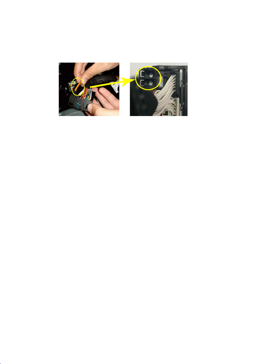
6. Plug the ber cable into one of the two ports at the back of the CAM-VL1-AD 40 way
quadlock connector on the CAM-VL1-AD power harness as shown below
7. Connect the OEM quadlock connector to the corresponding quadlock connector on
the CAM-VL1-AD power harness
8. Connect the CAM-VL1-AD quadlock connector to the back of the OEM head unit in
place of the original
9. Connect the CAM-VL1-AD power harness to the CAM-VL1-AD interface box
10. Unplug the blue antenna connector from the OEM head unit and connect it to the
corresponding plug on the CAM-VL1-AD antenna adapter. Then connect the antenna
adapter to the OEM head unit.
11. Connect the CAM-VL1-AD antenna adapter to the CAM-VL1-AD interface box
12. Connect the CAM-VL1-AD camera harness to the CAM-VL1-AD interface box
13. Fit the camera/s (sold separately) and route the wiring from the front/back of the
vehicle to the interface as desired
13. Connect the required camera connections to the CAM-VL1-AD camera harness.
The interface supports front and rear cameras which can be connected to the dedicat-
ed yellow RCA connections on the CAM-VL1-AD camera harness.
Connect the required ying wires to the vehicle:
Black GND
Red ACC OUT
White TRIG IN
Pink RIGHT TURN OUT
Blue LEFT TURN OUT
Purple CAM OUT
Yellow +B OUT
OEM
Quadlock
Connector
CAM-VL1-AD
Quadlock
Connector