Conrad Electronic FS20 S4A-2 User manual

Version 12/06
OPERATING INSTRUCTIONS
2/4-Channel wall-mounted
transmitter ‘FS20 S4A-2’
Item no. 61 72 50

2
Introduction
Dear customer,
Thank you for purchasing this product.
This product meets the requirements of both current European and national guidelines.
In order to preserve this condition and ensure the safe operation of the product we kindly ask
you to carefully follow these operating instructions!
Please read the operating instructions completely and observe the safety and operation notes
before using the product!
All company names and product names contained herein are trademarks of the
respective owners. All rights reserved.
Should you have any further questions, please contact our technical advisory service:
Germany: Tel. no.: +49 9604 / 40 88 80
Fax. no.: +49 9604 / 40 88 48
e-mail: [email protected]
Mon. to Thur. 8.00am to 4.30pm
Fri. 8.00am to 2.00pm

3
Table of contents
Page
1. Prescribed use ............................................................................................................... 4
2. Scope of delivery ........................................................................................................... 4
3. Technical specifications and features .......................................................................... 4
4. Explanation of icons ...................................................................................................... 5
5. Safety instructions ......................................................................................................... 5
6. Notes on batteries/rechargeable batteries ................................................................... 6
7. Inserting/replacing batteries .......................................................................................... 7
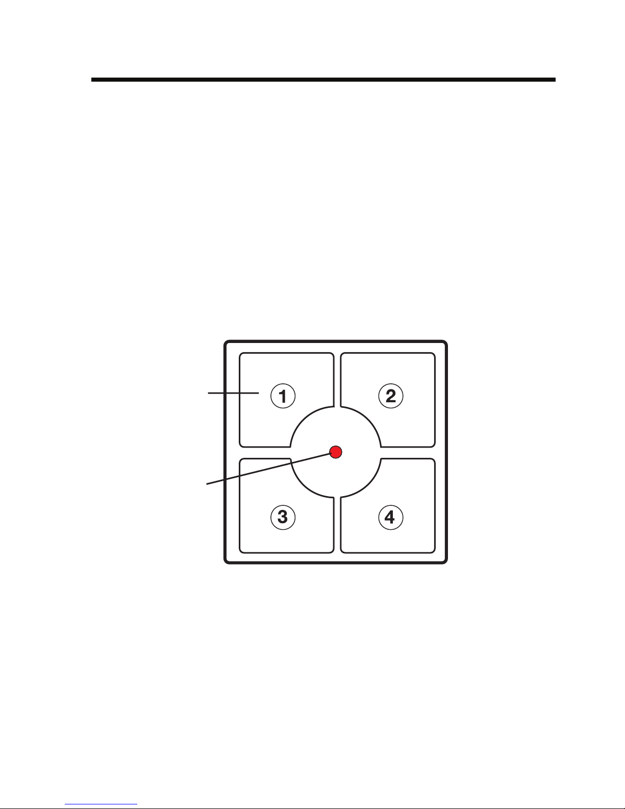
8. Control panel ................................................................................................................. 8
9. Installation ...................................................................................................................... 9
a) Adhesive mounting ................................................................................................. 9
b) Screw fixing ............................................................................................................. 9
10. Operation ..................................................................................................................... 11
a) Basic functions ...................................................................................................... 11
b) Using several transmitters ................................................................................... 11
c) Timer functions ..................................................................................................... 12
d) Double number of channels ................................................................................. 12
Switching between a single and double number of channels ............................ 12
Operation for a double number of channels........................................................ 13
Programming the timer for a double number of channels .................................. 13
11. FS20 address system basics ...................................................................................... 14
12. Integrating the ‘FS20S4A-2’ wall-mounted transmitter into the address system ..... 16
a) Setting the house code ........................................................................................ 16
b) Setting the addresses ........................................................................................... 16
1. Setting a single address (address group/subaddress) ................................ 17
2. Assigning function groups and master addresses ....................................... 17
3. Addressing for a double number of channels .............................................. 18
c) Resetting to the delivery state ............................................................................. 18
d) Example of an address assignment .................................................................... 19
13. Handling ....................................................................................................................... 21
14. Maintenance and cleaning .......................................................................................... 21
15. Disposal ....................................................................................................................... 22
a) General information .............................................................................................. 22
b) Batteries and rechargeable batteries .................................................................. 22
16. Tips and notes ............................................................................................................. 23
17. Declaration of conformity (DOC) ................................................................................. 23

4
1. Prescribed use
The sole purpose of the ‘FS20 S4A-2’ 2/4-channel wall-mounted transmitter is to remotely
control the various components of the FS20 wireless control system.
Make sure that the product does not get damp or wet. No part of the product may be modified
or adapted.
Any use other than the one described above may damage the product and can also increase
the risk of short-circuit, fire, electric shock etc.
All company and product names contained herein are trademarks of their respective owners.
All rights reserved.
2. Scope of delivery
• ‘FS20 S4A-2’ 2/4-channel wall-mounted transmitter
• Small piece of double-sided adhesive tape
• User manual
3. Technical specifications and features
• Devices are remotely controllable on 2 channels (two buttons per channel) or 4 channels
(one button per channel)
• Very secure data transfer as a result of extensive coding and address assignment options.
These also allow several neighbouring systems to be operated without interfering with each
other
• All settings remain even when the batteries are changed or a power outage occurs
• Power supply: 2 AG13 (=LR44) button cells
• Transmission frequency: 868.35MHz
• Modulation: AM
• Range: up to 100m (in free-field)
• Dimensions: 78mm x 78mm x 15mm (W x H x D)

5
4. Explanation of icons
This icon with an exclamation mark in a triangle points to particular dangers
associated with the handling, function or operation of the product.
The ‘hand’ icon indicates special tips and operational notes.
5. Safety instructions
The product’s guarantee becomes invalid, if the product is damaged as
a result of the failure to observe these operating instructions! We do not
assume any liability for any resulting damages!
Nor do we assume liability for damage to property or personal injury
caused by improper use or failure to observe the safety instructions. In
such cases the product’s guarantee becomes invalid.
This product is not a toy and should be kept out of the reach of children. Children could open
the battery compartment and swallow the button cells, which could be life-threatening! If this
happens, seek immediate medical care!
The product should only be used in dry indoor areas. It must not get damp or wet.
Do not use this product in hospitals or medical institutions. Although the product emits only
relatively weak radio signals, these may cause life-support systems to malfunction.
This may also be the case in other areas.
As switching operations provide no return information, there is no guarantee that all the
switched consumer loads really are ‘off’ or ‘on’.
When switching consumer loads, whose ‘on’ or ‘off’ status could cause damage, you may need
to directly check that their switch state is correct. Do not rely on switching commands that are
transferred by a transmission path!

6
6. Notes on batteries/rechargeable batteries
• Keep batteries/rechargeable batteries out of the reach of children.
• Do not leave batteries/rechargeable batteries lying around as they could be swallowed by
children or pets. In such a case, seek immediate medical care!
• Batteries/rechargeable batteries must never be short-circuited, taken apart or thrown into
a fire. They might explode!
• Leaking or damaged batteries/rechargeable batteries may cause acid burns, if they come
into contact with skin. Therefore, please make sure you use suitable protective gloves.
• Conventional batteries must not be recharged. There is the risk of fire and explosion!
• Make sure that the polarity (plus/+ and minus/-) is correct when inserting the batteries.
• If the device is not used for a longer period of time (for example, when stored), remove the
inserted batteries to prevent the batteries from leaking and causing damage.
• Always replace the whole set of batteries. Do not mix full batteries with half-full ones.
Always use batteries of the same type and manufacturer.

7
7. Inserting/replacing batteries
• Remove the front cover. On both sides there is an opening; the front cover can be carefully
clipped off here using a one penny coin (make sure that the front cover is directed towards
the base section, do not twist the front cover!).
• Now insert two LR44 batteries, observing the correct polarity (the plus pole has to point
upwards while the minus pole should point towards the circuit board.) Simply slide the
batteries into the holding bracket.
Do not turn any setting controls and do not ‘straighten’ any parts!
• Then replace the casing cover, snapping it into place.
Only one orientation of the cover is correct! The opening on the front cover must
lie above the small additional circuit board (you will see the marking ‘TOP’ on
the plastic of the front cover and on the base plate). These must be aligned
before you clip the casing parts together.
• If the LED on the front side of the wall-mounted transmitter does not light up when you press
the buttons or you find that the range of the wall-mounted transmitter decreases, then you
need to replace the old batteries with new ones.
Make sure you always replace the whole set of batteries.

8
8. Control panel
AFour control buttons
• 2-channel mode, channels ‘1’ and ‘2’
Channel 1 (buttons ‘1’ and ‘2’)
Channel 2 (buttons ‘3’ and ‘4’)
Left button: ‘OFF’, dim down
Right button: ‘ON’, dim up
• 4-channel mode, buttons ‘1’ to ‘4’ correspond to channels ‘1‘ to ‘4’
BControl indicator/LED
The battery compartment is located under the front cover.
Figure 1: Wall-mounted transmitter
The ‘top’ orientation of the wall-mounted transmitter (the orientation is not
recognisable on the front panel) is aligned with the lettering on the back of the
wall-mountedtransmitterorthecircuitboardinsidethewall-mountedtransmitter,
the small additional circuit board lying beneath it.
A
B

9
9. Installation
You can mount the wall-mounted transmitter either by simply sticking its casing to a suitable
surface or by screwing it on using the available mounting holes.
The places in the casing that are marked with ‘TOP‘ must always point upwards
(the small additional circuit board in the casing lies beneath).
a) Adhesive mounting
• Use the supplied double-sided adhesive tape, for example, to mount the device to a wall.
• Carefully clean both surfaces where the adhesive is to be applied (wall-mounted transmit-
ter and mounting surface).
Fatty residues (also fingerprints), moisture, lubricating films and silicon residue, in particu-
lar, can prevent the device from adhering properly.
• Remove the protective strip from the adhesive tape and stick it to the back of the wall-
mounted transmitter. Press on the adhesive tape firmly and evenly in order to ensure firm
a adherence.
• Remove the second protective film and place the wall-mounted transmitter onto the desired
attachment surface, keeping it straight.
You can ensure that the wall-mounted transmitter is extra securely fixed by
firmly pressing on the base cover alone (first remove the front panel and
unscrew the circuit board).
Make sure that the device is straight/level as it not possible to make
mounting adjustments afterwards!
b) Screw fixing
• Open the casing by carefully lifting the front cover on the side opening slots using a one
penny coin, for example.
• Place the lower part onto the desired mounting location, keeping it straight, and use a
pencil, for example to mark the drilling holes through the mounting holes of the casing.

10
• Two diagonally opposed screws will usually suffice for mounting the device to a wall.
Depending on the type of surface (for example cement/brick), you should first drill two holes
using a 6 mm drill, for example.
Be careful not to drill through any electricity lines, gas or water pipes. Life-
threatening danger!
• Use screws to attach the base of the wall-mounted transmitter.
Use lens head screws or machine screws with washers, and no countersunk
screws (their splaying effect can cause the plastic rear panel of the wall-
mounted transmitter to break)!
• Close the casing of the wall-mounted transmitter by carefully and evenly pressing the front
cover onto the lower part.

11
10. Operation
Please note:
In the delivery state the components of the FS20 wireless control system (e.g.,
a wireless switch socket) do not respond to remote control commands from the
wall-mounted transmitter. They must first be addressed according to the
instructions provided in the respective device’s user manual.
Only afterwards can the functions be controlled.
a) Basic functions
Buttons are pressed quickly (switch) or for longer than 0.4 seconds (dim), as required.
The ON command (or dim up) is globally allocated to the respective right
button of a channel (buttons ‘2’ and ‘4’), while the OFF command (or dim
down) is allocated to the associated left button (‘1’ and ‘3’).
The control indicator/LED briefly lights up to signal that a command has been transmitted.
Now you can program and operate the basic functions of the FS20 components.
Please also read the following sections, if you require an extended system with
several components or you wish to use the additional functions.
b) Using several transmitters
In the delivery state each transmitter in the FS20 wireless control system has its own, randomly
set house code.
If you want to jointly control one or several receivers via different transmitters,
you first need to coordinate the transmitters’ house codes. The same house
code must be set for each transmitter.
Make sure you coordinate or set this shared house code for all the
transmitters before programming the receivers for the first time, as the
associated house code is also sent to the receiver during this procedure.

12
The transmitters’ channels are already set to the same addresses and only need to be changed
if required, for example, if you are using an extensive FS20 wireless control system with
numerous receivers/transmitters.
See the relevant example in section 12. d).
c) Timer functions
In order to program a receiver’s timer function you must simultaneously press the button
combination (e.g., buttons ‘1’ and ‘2’ for channel 1) that have been assigned to the receiver
for one to five seconds (1 sec to 5 sec) on the wall-mounted transmitter.
This command is used to start as well as to stop the programming of the timer.
For information on how to program the timer, see the instructions in the
receiver’s user manual.
d) Double number of channels
The wall-mounted transmitter can be used as a 2-channel wall-mounted transmitter (default
setting: two buttons are assigned to each channel, for example, buttons ‘1’ and ‘2’ are
assigned to channel 1) as well as a 4-channel wall-mounted transmitter (each channel now
only has a single button assigned to it and no button combination, e.g., button ‘1’, for channel
1, button ‘2’ for channel 2 etc.).
• Switching between a single and double number of channels
You set a double number of channels (four individual switching channels) by simultane-
ously pressing the buttons ‘2’ and ‘3’ (see section 8. Control panel) for at least five
seconds. The control indicator/LED lights up briefly to confirm the setting.
You set a single number of channels (four switching channels, each with two buttons) by
simultaneously pressing the buttons ‘1’ and ‘4’ for at least five seconds. The control
indicator/LED lights up briefly to confirm the setting.
Please note:
Different operating and programming instructions apply when a double number
of channels has been set!

13
• Operation for a double number of channels
A different channel is assigned to each button. The control indicator briefly lights up to
signal that a command has been transmitted.
Switching
Pressing a button quickly (for less than 0.4 seconds) sends a switching command.
Whenever a button is pressed the addressed receiver changes its switch state from ‘OFF’
to ‘ON’ or from ‘ON’ to ‘OFF’.
Dimming
Pressing a button for longer than 0.4 seconds sends a dimming up or a dimming down
command until the button is released (lamp is dimmed up to its maximum and then dimmed
down to its minimum etc.).
Here too, the dimming state (up or down) changes whenever a button is pressed. If, for
example, the last command caused a lamp to dim up, then pressing the button again would
result in the lamp dimming down.
• Programming the timer for a double number of channels
In order to program a receiver’s timer function, proceed as follows:
Press the button that is assigned to the receiver (keep the button pressed!). Press the
button next to it for one to five seconds (1 sec to 5 sec) and then release it. Only afterwards
should you release the button that you pressed first.
This procedure is used to start as well as to stop the programming of the timer.
For information on how to program the timer, see the instructions in the
receiver’s user manual.

14
11. FS20 address system basics
The FS20 wireless control system operates with a ‘house code’. This means that your
neighbour can also use the same wireless control system and the two systems will not interfere
with each other (provided that the house code has been programmed differently).
256 different addresses can be set within a house code. These addresses are divided into four
address types (available number is in brackets):
• Single addresses (225)
• Function group addresses (15)
• Local master addresses (15)
• Global master address (1)
One address from each address type can be assigned to each receiver. This means that each
receiver can respond to up to four different addresses, but only ever to one address per
address type. If you need a receiver to respond to more than one transmitter, you can program
the transmitters to the same address or, if different transmitter address types have been set,
you can program the receiver consecutively to these different addresses.
The individual address types have the following function:
• Single addresses
Each receiver should be set to a single address so that it can be controlled separately.
• Function group addresses
Several receivers are defined as a functional unit by being assigned to a function group
address. If, for example, all the lamps in a house are assigned to a function group, then all
the lamps in the entire house can be switched on or off by pressing one button.
• Local master addresses
Several receivers are spatially defined as one unit and controlled via the local master
address. If, for example, all the receivers in a room are each allocated to a local master
address, then all you need to do is press one button when leaving the room to switch off
all the consumer loads in the room.
• Global master address
Several receivers are assigned to the global master address and are jointly controlled via
this address. All the consumer loads can easily be switched off simply by pressing one
single button when leaving a house, for example.

15
See the example in section 12. d).
This address system opens up a variety of possibilities. You can even implement access
authorisations by assigning three garage doors to different single addresses and a joint
function group (‘garage doors’), for example.
Several people can then each be given a hand-held transmitter with a relevant single address
for one garage door, while all the garage doors can be opened via a hand-held transmitter with
a programmed function group address, or all the doors can be automatically closed in the
evening via an FS20 timer.
The various address types and addresses are only set on the transmitter
and these settings are transmitted to the receivers via the address
assignment. A receiver must be in programming mode in order for this
address assignment to take place.

16
12. Integrating the ‘FS20 S4A-2’ wall-mounted
transmitter into the address system
The house code, an address group and a subaddress are used for coding the wall-mounted
transmitter and its switching channels. You can also use special address group assignments
to program the wall-mounted transmitter as a local or global master.
Only the ‘1’, ‘2’, ‘3’ and ‘4’ buttons are used for entering the eight-digit
house code, the two-digit address groups and the two-digit subaddresses (see
the figure in section ‘8. Control Panel’).
This addressing makes 225 single addresses, 15 function groups, 15 local master addresses
and 1 global master address available within each house code to the wall-mounted transmitter.
a) Setting the house code
Once the batteries have been inserted for the first time, the wall-mounted transmitter selects
a random house code.
If required, this house code can be changed as follows:
• Keep the ‘1’ and ‘3’ buttons on the wall-mounted transmitter pressed for five seconds
until the control indicator/LED flashes every second.
• Now use the ‘1’, ‘2‘, ‘3’ and ‘4’ buttons to enter your system’s eight-digit house code.
This must be identical for all the remote control transmitters in the FS20 wireless control
system (as a precaution, make a note of this code and keep it safe).
Example: 23141342 (1= button ‘1’, 2= button ‘2’, 3= button ‘3’, 4= button ‘4’)
• The programming mode ends automatically once you have entered the eighth digit. The
control indicator/LED goes out.
b) Setting the addresses
A channel’s address comprises a two-digit address group and a two-digit subaddress (for
example, 1131, address group 11, subaddress 31).
The address group ‘11’ is factory set for all channels.
If several transmitters are to be operated at the same time and control different receivers, then
different addresses need to be set on the transmitters.

17
The following address combinations (address group/subaddress) are preassigned to both
button combinations of the wall-mounted transmitter:
Button combination: 1 2
Address: 11 11 11 12
See the ‘Addressing for a double number of channels’ subsection below for
information on addressing for a double number of channels.
1. Setting a single address (address group/subaddress)
To set the address group/subaddress proceed as follows:
-Simultaneously keep both buttons of the respective button combination pressed for at
least five seconds (buttons ‘1’ and ‘2’ for channel 1, buttons ‘3’ and ‘4’ for channel
2). The control indicator/LED will now blink every second.
- Enter a two-digit address group and a two-digit subaddress using the ‘1’,‘2’, ‘3’ and
‘4’ buttons.
Example: 1431 (address group 14, subaddress 31)
- The programming mode ends automatically once you have entered the fourth digit. The
control indicator/LED goes out.
The address group 44 and the subaddress 44 both have a particular meaning
(see the following item)!
2. Assigning function groups and master addresses
Function groups (44xx)
If you enter 44 as the address group, then the subaddress (provided this is not also set to
44; see the following section) is defined as a function group. 15 different function groups
between 4411 and 4443 can then be defined.
Possible are: 4411, 4412, 4413, 4414, 4421, 4422, 4423, 4424, 4431, 4432,
4433, 4434, 4441, 4442, 4443
Local master (xx44)
If you only set the subaddress to 44, then this channel functions as a local master within
the set address group. All receivers that are programmed with this local master address are
controlled simultaneously.

18
Possible are: 1144, 1244, 1344, 1444, 2144, 2244, 2344, 2444, 3144, 3244,
3344, 3444, 4144, 4244, 4344
Global master (4444)
If you set the address group and subaddress of a channel to 44, then this channel functions
as a global master. All receivers that are programmed with this global master address are
controlled simultaneously.
The only global master is 4444.
3. Addressing for a double number of channels
To change the address group and subaddress for a single button proceed as follows:
- Press and hold the button to be programmed.
Now also press the left/right button next to it. Keep both buttons pressed simultaneously
for at least five seconds!
The control indicator/LED blinks every second, indicating that the programming mode
has now been activated.
- Now enter a two-digit address group and a two-digit subaddress using the ‘1’,‘2’,
‘3’ and ‘4’ buttons.
Example: 1112 (11 = address group, 12 = subaddress)
- The programming mode ends automatically once you have entered the fourth digit. The
control indicator/LED goes out.
c) Resetting to the delivery state
In order to reset all the transmitter’s settings to the delivery state you need to first simultane-
ously press and hold the ‘2’ and ‘4’ buttons (for at least five seconds) until the LED Indicator
lights up.
Now release these two buttons and then press any button. As soon as the LED goes out, the
transmitter returns to its initial state.

19
d) Example of an address assignment
When you require a large, extended system it is advisable to select addresses systematically
so that you have an overview of the addresses that have already been assigned and so that
you can jointly control the programmed receivers simply and meaningfully in groups.
1111
1144
4411
4444
1122
1144
4444
1131
1144
4444
1211
1212
4411
4444 1311
4411
4444
1411
4411
4444
1412
4444
A
BC
D
Global
master address
4444
Local
master address,
e.g. 1144
House code, e.g.,
1234 1234
Function group 44xx,
e.g. 4411 ceiling lamps
Figure 2: Example of an address assignment
A different address group has been assigned to each room:
• Room A: 11
• Room B: 12
An awning is also allocated to room B.
• Room C: 13
• Room D: 14

20
Possible address groups are:
11, 12, 13, 14, 21, 22, 23, 24, 31, 32, 33, 34, 41, 42, 43
In order to be able to separately control each receiver, you need to program each receiver to
a single address. A subaddress is also required in addition to the address group that is already
selected (room A: 11, room B: 12, room C: 13, room D: 14).
The following 15 subaddresses are possible for each address group:
11, 12, 13, 14, 21, 22, 23, 24, 31, 32, 33, 34, 41, 42, 43
In the example the awning is programmed to the single address 1211, which is comprised of
the address group 12 and its subaddress 11.
All the receivers in room A have also been programmed to a local master address (1144 in the
example).
For the local master address 44 is always set as the subaddress, while one of
the 15 local master addresses (11, 12, 13, 14, 21, 22, 23, 24, 31, 32, 33, 34,
41, 42, 43) can be selected via the address group.
Example: 1144, address group 11, subaddress 44
All the lamps in the house can be controlled via the global master address 4444.
The awning was deliberately not programmed to this address and can therefore only be
addressed via its single address (1211). It must be operated separately in this example.
The ceiling lamps in all the rooms are also combined in a function group (4411 in the example,
address group 44, subaddress 11) and can therefore be jointly controlled.
To select one of the 15 function groups, you need to set 44 as the address group and a value
between 11 and 43 (11, 12, 13, 14, 21, 22, 23, 24, 31, 32, 33, 34, 41, 42, 43) as the subaddress.
Table of contents
Other Conrad Electronic Transmitter manuals