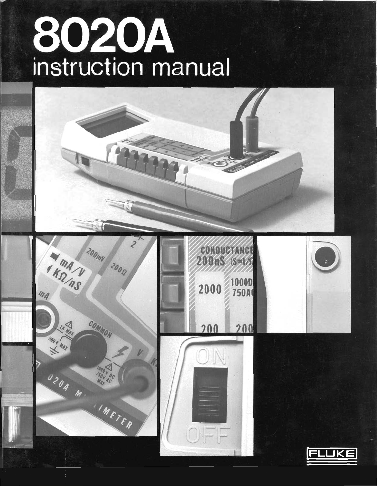
Fluke 8020A User manual


instruction manual
This manual documents the Model 8020A and its assemblies at the revision level shown in Appendix A. If
yourinstrument containsassemblies withdifferent revisionletters, it will be necessaryforyou toeither update
or backdate this manual. Refer to the supplemental changelerrata sheet for newer assemblies, or to the
Appendix A for older assemblies.
John Fluke Mfg. Co., Inc.
P.O.
Box 43210 Mountlake Terrace, Washington 98043
Rev.
1
8/77
Rev.
2
5/78

Dear Customer:
Congratulations! We at Fluke are proud to present you with the Model 8020A
Multimeter. This instrument represents the very latest in integrated circuit and
display technology. Asaresult, the endproduct isaruggedandreliableinstrument
whose performance and design exhibit the qualities of
a
finely engineered lab
instrument. It also provides some unique measurement capabilitiesin addition to
those normally found in an ordinary multimeter.
Tojirllyappreciate and protect your investment, we suggest that you takea few
moments toread the manual. Asalways, Fluke stands behind your 8020A with a
full one
-
year warranty and a worldwide service organization.
If
the need arises,
please don't hesitate to call on us
Thank you for your trust and confidence.
JOHN
FLUKE
MFG.
CO., INC.

Some semiconductors and custom IC's can be
damaged by electrostatic discharge during
handling. This notice explains how you can
minimize the chances of destroying such devices
by:
1.
Knowing that there is a problem.
2.
Learning the guidelines for handling them.
3.
Using the procedures, and packaging and
bench techniques that are recommended.
TheStaticSensitive(S.S.) devicesareidentified in theFluketechnical manualparts list withthesymbol
8'
@
,,
The following practices should be followed to minimize damage to S.S. devices.
1.
MINIMIZE HANDLING
3.
DISCHARGE PERSONAL STATIC
BEFORE HANDLING DEVICES
2.
KEEP PARTS IN ORIGINAL CONTAINERS
UNTIL READY FOR USE.
4.
HANDLE S.S. DEVICESBY THE BODY

5.
USE ANTI
-
STATIC CONTAINERS FOR
HANDLING AND TRANSPORT
8.
HANDLE S.S. DEVICES ONLY AT
A
STATIC
-
FREE WORK STATION
9.
ONLY ANTI
-
STATIC TYPE SOLDER-
SUCKERS SHOULD BE USED.
10.
ONLY GROUNDED TIP SOLDERING
IRONS SHOULD BE USED.
6.
DO NOT SLIDE S.S. DEVICES OVER
ANY SURFACE
Anti
-
static bags, for storing S.S. devices or pcbs
withthesedevicesonthem,canbeorderedfromthe
JohnFlukeMfg.Co., Inc..Seesection
5
inanyFluke
technical manual for orderinginstructions. Usethe
followingpartnumberswhenorderingthesespecial
bags.
John Fluke Bag Size
Part No.
453522 6
"
x
8
"
453530 8
"
x
12
"
7.
AVOID PLASTIC, VINYL AND STYROFOAM
453548 16
"
x
24
"
IN WORK AREA
454025 12
"
x
15
"

Table of Contents
SECTION TITLE PAGE
1 INTRODUCTIONANDSPECIFICATIONS
......................
1
-
1
INTRODUCTION
....................................
1-1
PREPARING FOROPERATION
.......................
1-1
........................................
Unpacking 1
-
1
Battery Installation
.................................
1
-
2
GETTING ACQUAINTED
.............................
1
-
2
Physical Features
..................................
1
-
2
InitialCheck
-
Out Procedure
.........................
1
-
2
..................................
SPECIFICATIONS 1
-
4
.................................
OPERATINGINSTRUCTIONS 2
-
1
2.10
.
INTRODUCTION
...................................
2
-
1
2.3 . OPERATING NOTES
.................................
2
-
1
2.5
.
Input Power
......................................
2
-
1
2-12
.
Display Readings
..................................
2
-
2
2.15 . Input ConnectionstoCOMMON
.....................
2
-
2
2.17 . Input Overload Protection
...........................
2
-
2
2.19 . Fuse Replacement
..................................
2
-
3
2.22
.
AC Measurement
..................................
2
-
3
2.24 . Resistance
........................................
2
-
3
2.27 . Voltage AC/DC
...................................
2-4
2.30
.
Current AC/DC
...................................
2
-
5
2
-
33. Conductance
......................................
2
-
5
2.37 . OPERATION
.......................................
2
-
6
2.39
.
APPLICATIONS
....................................
2
-
6
2.41
.
Transistor Tester
...................................
2
-
7
2
-
46
.
LeakageTester
....................................
2
-
8
3 THEORYOFOPERATIONS
...................................
3
-
1
3.1 . INTRODUCTION
....................................
3
-
1
..............
3.3
.
OVERALL FUNCTIONAL DESCRIPTION 3
-
1
3.8 . BLOCK DIAGRAM ANALYSIS
........................
3
-
2
3.9
.
A/DConverter
....................................
3
-
2
3.18
.
InputSignalConditioners
...........................
3
-
2
4 MAINTENANCE
..............................................
4
-
1
4.1 . INTRODUCTION
....................................
4
-
1
............................
4.3 . SERVICE INFORMATION 4
-
1
4.7
.
GENERALINFORMATION
...........................
4
-
2
i
(Continued on next page)

SECTION TITLE PAGE
.................................
Access Information 4
-
2
..........................................
Cleaning 4-3
..........................
Battery/ Fuse Replacement 4
-
3
PERFORMANCE TEST
................................
4-3
...................................
Initial Procedure 4-3
DisplayTest
.......................................
4-3
........................
Resistance/Conductance Test 4
-
4
DC VoltageTest
....................................
4-4
AC VoltageTest
....................................
4-4
....................................
DCCurrent Test 4-5
CALIBRATION
.....................................
4
-
5
TROU BLESHOOI'ING
..............................
4
-
5
..............................
5
LISTOFREPLACEABLEPARTS 5
-
1
5-
1
.
IN~I'KODIJ("I'I0N
.....................................
5-1
5
-
4
.
HOW TOOBTAIN PARTS
.............................
5-1
................................
6 OPTIONS ANDACCESSORIES
6
-
1
.....................................
INTRODUCTION 6
-
1
......................
DELUXE CARRYINGCASE(C90) 6-1
........................
BATTERY ELIMINATOR(A81) 6
-
1
......................
TEMPERATURE PROBE (801'-150) 6
-
2
Introduction
......................................
6-2
......................................
Specifications 6-2
CURRENTTRANSFORMER (801-600)
.................
6
-
2
Introduction
.......................................
6
-
2
......................................
Specifications 6-2
HIGH VOLTAGE PROBE(80K-40)
....................
6-2
.......................................
Introduction 6
-
2
Specification3
......................................
6
-
2
HIGH FREQUENCY PROBE(8IRF)
..................
6-2
......................................
Introduction 6
-
2
......................................
Specil'ications 6-2
7 SCHEMATIC DIAGRAMS
.....................................
7
-
1
SERVICE CENTERS
..........................................
7
-
3
...........................................
SERVICE REPORT 7
-
5
WARRANTY
APPENDIX A
.
Manual Change lnformatlon

List of
I
I
lustrations
1
FIGURE TITLE PAGE
1.1
.
Controls. Indicators. Connectors
.......................................
1
-
2
2.1
.
Recommended MethodforRemoving Battery Cover
......................
2
-
1
2.2
.
WaveformConversion
...............................................
2
-
4
2.3
.
Voltage Measurement Error Calculations
.....................................................
(LoadingError) 2
-
4
2
-
4
.
Current Measurement Error Calculations
(Burden Voltage Error)
................................................
2
-
5
2.5
.
Conductance
-
to
-
Resistance Conversion Scales
..............................................
and Interpolation Table 2
-
6
........................................
2.6
.
Selectinga Rangeand Function 2
-
6
2.7
.
Transistor BetaTest Fixture
...........................................
2-7
3.1
.
8020ASimpl~fiedBlock Diagram
......................................
3
-
1
3.2
.
Dual
-
Slope A/D Convertor
...........................................
3
-
3
3.3
.
InputSignalConditioners
............................................
3
-
4
.....................................
4.1
.
Calibration Adjustment Locations 4
-
2
................................................
5.1
.
8020APCBAssembly 5
-
3
...................................................
6.1
.
8020AAccessories 6
-
1

List
of
Tables
TABLE TITLE
PAGE
.......................................
Controls. Indicators.Connectors 1
-
3
................................................
8020A Spectifications
1
-
4
.....................................
Summaryof Input Overload Limits
2
-
3
Resistance Ranges and Their Voltage/Current
..........................................................
Capability
2
-
3
..................................
Listof Recommended Test Equipment 4
-
1
.......................................
Resistance/ConductanceChecks 4
-
4
..................................................
DCVoltageChecks 4
-
4
ACVoltage Checks
..................................................
4
-
4
.............................................
DCCurrent
(mA)
Checks 4
-
5
...............................................
TroubleshootingGuide 4
-
6

Section
1
Introduction
&
Specifications
1
-
1. INTRODUCTION
1
-
2. The Fluke Model 8020A is a portable 3%
-
digit,
pocket
-
sized multimeter that is ideally suited for field,
lab, shop, bench, or homeapplications. It weighsinatan
impressive369 grams (13 ounces) with battery,and packs
more measurement power than the heavy
-
weights.
Here's a review of some of the features that qualify the
8020A as a real pro:
All VOM functions plus the versatile conductance
function (six in all) are included as standard.
DC Voltage
-
100 pV to lOOOV
AC Voltage
-
100 pV to 750V
DC Current
-
1 pA to 2000 mA
AC Current
-
1 pA to 2000 mA
Resistance
-
0.1R to 20 MR
Conductance
-
0.1 nS to 200 nSand .001 mS to 2 mS
(S
=
siemens
=
1
/
R).
CONDUCTANCE!! A new multimeter function that
allows fast, accurate, noise free resistance measure
-
ments up to 10,000 MR.
Line operation is possible using a Model A81 Battery
Eliminator (See Section 6, accessories).
Effective overload and transient protection on all
ranges.
overrange indication on each range.
Long term calibration (1 year) is achieved by using
high stability components, and minimizing adjustments
(three total).
Full auto
-
polarity operation.
Dual slope integration toensure fast, accurate, noise
free measurements.
A complete line of range extending accessories is
available.
1-3. PREPARING FOR OPERATION
1
-
4. Unpacking
1
-
5. When received, the 8020A shipping carton
The
latest IC
and
is
used
to
should contain the items listed below. Account for, and
achieve the lowest possible component count. This, in
inspect
each
item
before the
is
discarded.
In
the
turn, ensures reliability, accuracy, stability and a really event of a damaged instrument, contact your nearest
rugged, easy
-
to
-
handle instrument. John Fluke Service Center as listed at the rear of this
Up to 200 hours of continuous operation can be
expected from a single, inexpensive, 9V, alkaline battery
(transitor radio/calculator type).
Low battery voltage automatically detected and
displayed.
No needles to bend. No parallax and no zero adjust.
Just a high contrast, easy
-
to
-
read, 3-112 digit, liquid
crystal display.
manual. Please retain. and use the shipping container if
reshipment is required.
Contents:
1
-
Model 8020A Multimeter
1
-
Model 8020A Instruction Manual
1
-
9V Battery
1
-
Set of Test Leads (red and black)
1
-
8020A Operator's Guide (plastic card)
X
-
Accessories as ordered

1
-
6. Battery Installation
CAUTION
-
WARNING
BATTERY OR FUSE INSTALLATIONIRE-
PLACEMENT SHOULD ONLY BE PER
-
FORMED AFTER THE INPUT SIGNAL AND
THE TEST LEADS HAVE BEEN REMOVED
FROM THE INPUT TERMINALS, AND THE
POWER SWITCH IS SET TO OFF.
.
1
-
7. To install the battery, locate the battery-
compartment cover on the bottom of the 8020A, and
using both thumbs slide it away from the case screw to
expose the battery compartment. See Figure 2
-
1. Then,
extend the battery
-
clip and cablefrom thecompartment,
and attach the 9V battery (supplied with the 8020A).
While the cable is extended, check the fuse
-
clip on the
back of the battery
-
clip. It should contain an AGX 2
(2A/250V)fuse(a metricfuse, type 171100
-
2, is supplied
with units having white and whitelred wires going tothe
fuse clip). Carefully position the battery, cable,and clip
within the confines of the battery compartment by
inserting cable first, followed by fuse
-
end of battery
assembly. Finally, close the compartment by sliding the
cover into position
If
fuse replacement is necessary, do not
substitute fuse type or rating, for metric fuse
cllpsusetype171100-2.OtherwlseuseAGX2.
1
-
8. GETTING ACQUAINTED
1
-
9. Before attempting to use your 8020A, we
suggest that you take a few minutes to get acquainted.
First, let's find out what all the buttons are for. Then
we'll check it out to make sure it's working properly.
1
-
10. Physical Features
1
-
11. All of the buttons, switches, and other
externally accessible physical features of the 8020A are
shown in Figure 1
-
1 and described in Table 1
-
1. Locate
each of the features on your instrument as you read the
functional description.
1
-
12. lnitlal Check
-
Out Procedure
1
-
13. Now that you have installed the battery, and
know where everything is, let's make sure the unit is
working properly. We'll run through a simple check
-
out
1
-
2
Flgure 1-1. Controls, Indicators, Connectors

procedure starting with turn
-
on. No equipment other
than the test leads will be required.
If
a problem
is
encountered, please recheck the battery, fuse, switch
settings, and test lead connections before contacting
your nearest authorized John Fluke Service Center.
ITEM
NO. NAME FLlNCTlON
1 Display A
3%
digitdisplay (1999max) withdecimalpointandminuspolarity indication.
Used toindicate measuredinput values, overrangeconditionand low battery
condition.
NOTE
2
3
4
5
6
7
8
10
11
This procedure is intended to verify overall
instrument operation, and is not meant as a
substitute for the formal Performance Test
given in Section
4.
Limits shown exceed the
specificationsbecausetheprocedureuses one
measurement function to check another.
a. Set the power switch toOFFand allrange and
function switches to the released (out) position.
Power Switch
TiltBail
Battery Eliminator
Connector
Battery Compartment
and Cover
V/KQ lnput Connector
COMMON Input
Connector
mA lnput Connector
mA/V-KQ/nS
Switch
Range Switches
DC/AC Switch
b. Set the power switch to ON and observe the
display. It should read 00.0
f
0.1.
A slide switch used to turn the instrument off and on.
A removablefold
-
out stand which allows the instrument tobe either tiltedfor
bench
-
topapplications or hung from a hook inthe absenceof awork surface.
An external input power connector for use withtheModel A81Battery Eliminator
accessory.(A81isavailableinavarietyof voltageandplugconfigurations.See
Section 6).
Cover for the 9V battery and the current
-
protection fuse.Thecover is removedby
pushing it away from the case screw.
Banana jack connector used as the high input for all voltage, resistance and
conductance measurements.
Banana jack connector used as the low or common input for all measurements.
Banana jack connector used as the high input for all current measurements.
A push
-
push switch (push on
-
push off, do not pull to select function) which
operatesinconjunctionwiththehighinputconnectorstoselecteitherthe mA/Vor
kQ (conductance) measurement functions. When in or depressed it selects kQ.
The out position selects mA or V depending upon the location of the high input
lead.
Interlocked push
-
button switches for selecting ranges, i.e., pressing the desired
range switchselects that 'rangeand cancels previous switch depressions. Donot
pull switches to select a range.
Voltage: 200 mV, 2V, 20V, 200V, lOOOV dc/750V ac
Current: 2 mA, 20 mA, 200 mA, 2000 mA
Resistance: 200Q, 2 kQ, 20 kQ, 200 kQ, 2000 kQ, 20 MQ
Conductance: 200 nS or 2 mS (S
=
siemens
=
1/Q
=
international unit of
conductance). Requires simultaneous depression of two range
switches.
A push
-
push switch (push on
-
push off, do not pull to select function) used to
select the ac or dc measurement function when measuring current or voltage.
When in, ordepressed,theacfunctionisselected.Out selectsdc.Switchmaybein
either position when making resistance or conductance measurements.
c. Connect the red test lead to the V/Kninput
terminal.
d. Touch the red probe tip to the COMMON
input terminal, and sequentially depress eachof
the six grey range switches starting at the top
(20 Ma). The display should read zero
f
one
digit and the decimal point should be
positioned as follows:

k.
Touch the red probe tip to the mA input
connector and press the 200a switch. The
display should read 99.0 to 101.0.
1. Press the 2 KR switch. The display should read
.099 to .101. Remove the probe from the mA
input connector.
e. Press the 20V range switch and remove the
probe from the COMMON input terminal. m. Simultaneously depress the 2000 KRand the 20
MR range switches. This selects the 200 nS
f. Look inside of the battery eliminator connector range. The display should read 00.0 to 01.0
on the right side of the 8020A and locate the (minimum conductance, maximum resistance).
connector contacts(center post and sidecontact
as shown in Figure 1
-
1). n. Touch the red probe tiptothe COMMONinput
connector. An overrange indication should be
g. Touch the red probe tip to the center post of the displayed since conductance is the reciprocal of
battery eliminator connector. The display resistance.
should read approximately
-
6.1 (V dc) Connect the black test lead to the COMMON
input connector.
h. Touch the probe tip to the side contact of the
battery eliminator connector. The display p. Depress both the AC/DC switch and the 750V
should read approximately 2.9
(V
dc). Notice ac range switch. Set the mA/V-KR switch tothe
that the sum of the two readings is equal to the voltage (out) position.
battery voltage (typically,
8
to 10Vdc). Remove
the probe from the battery jack.
I
.
Depress the lower white button (KO) and
sequentially depress each of the six range
switches. The display should read 1 as the most
significant digit with no other numbers shown.
This is the standard overrange indication.
Notice that the decimal point changes position
with the range switch settings just as it did in
step d of this procedure.
WARNING
THE LOCAL LINE VOLTAGE IS MEASURED
IN THE FOLLOWING STEP. BE CAREFUL
NOT TO TOUCH THE PROBE TIPS WITH
FINGERS, OR TO ALLOW THE PROBE TIPS
TO CONTACT EACH OTHER.
q-
Measure the local ac line voltage at a
convenient output receptacle. The voltage
should be displayed with 1 volt resolution.
r. If the 8020A has responded properly to this
j.
Touch the red probe tip to the COMMON point, it is operational and ready for use.
input terminal, and sequentially press each of
the grey buttons. The display should read zero
1-14.
SPEC~F~CAT~ONS
at each range setting. Lead resistance may be
sufficient to cause a one or two tenths (0.1 or 1
-
15. Detailed specifications for the Model 8020A are
0.20) indication on the 200R range. given in Table 1
-
2.
1
Table
1
-
2.
8020A Specifications
ELECTRICAL
.....................
.The electrical specifications given assume an operating
temperature of 18°C to 28"C,humidity up to 9O0/0, and a 1
-
year
calibration cycle.
FUNCTIONS
......................
.DC Volts, AC Volts, DC Current, AC Current, Resistance and
Conductance.
DC VOLTS
Ranges
.........................
.f
200 mV, *2V,
f
20V,
f
200V, i1000V
Accuracy
.......................
.+(0.25% of reading +1 digit), all ranges
................
InputImpedance .10 Mn, all ranges
NormalModeRejection Ratio
....
.60 dBat 60
Hz
or60dB at 50
Hz.
CommonMode Rejection Ratio
...
.I00 dB at dc,
50
Hz
and
60
Hz
OvervoltageProtection
..........
.1000V dc or peak ac on all ranges

8020A
Table
1
-
2. 8020A
Specifications(Contlnued)
AC VOLTS
.........................
Ranges 200 mV, 2V, 20V, 200V, 750 rms
Accuracy See table
................
Input Impedance .10 Mf2, capacitance <I00 pF, all ranges
..........
OvervoltageProtection .1000V dc or 750V rms max or 107volt
-
Hertz (whichever is less).
200 mV range;15 seconds max over 300V ac.
RESISTANCE
.........................
Ranges .20021, 2kf2, 20 kf2, 200 kf2, 2000 kf2, 20 Mf2
Accuracy
......
2kf2,20kf2,200kf2,2000kf2
f
(0.2% of reading
+1
digit)
.........................
20021 .f(0.3% of reading +3 digits)
........................
20 Mf2
.f
(2.0% of reading +1 digit)
Full Scale Voltage
200f2,20 kf2,2000 kf2
..........
.<0.25V dc (in
-
circuit ohms)
.................
200 kf2,20Mf2 .>0.7V dc
]
(diode test
+
)
...........................
2 kf2 >1 .OV dc
Open Circuit Voltage
..........................
2 kf2 .<3.5V dc
...............
Allother ranges .<1.5V dc
Diode Test Ranges
20021,20 kf2,2000kf2
..........
.Typical silicon junction will
not
be turned
-
on by these ranges.
2 kf2,200kf2,20 Mf2
...........
.Typical silicon junction will be turned
-
on by these ranges. The
2 kf2range will supply atypicalforward current of 0.6 mA,andis
preferred for testing semiconductor junctions (marked
+).
..........
OvervoltageProtection 300V dc or rms, on all ranges.
CONDUCTANCE
.........................
Ranges .2 mS, 200 nS
Accuracy
.........................
2 mS
.f
(0.3% of reading +1 digit)
200 nS
...................
;
.....
f
(2.0% of reading +10 digits)

Table
1-2.
8020A
Speclflcatlons(Concluded)
---
-
Open
-
Circuit Voltage
...........................
2mS <3.5V
.........................
200nS
<I
.5V
.....................
DiodeTest ..Both ranges will forward bias a typical silicon PN junction.
.............
Overload Protection .300V dc/rms on all ranges.
DC CURRENT
.........................
Ranges
.f
2 mA,
f
20 mA,
f
200 mA,
f
2000 mA
.......................
Accuracy
.f
(0.75% of reading +1 digit), all ranges
Burden Voltage
2 mAto200 mA Ranges
........
.0.25V dc max at full scale
2000 mARange
...............
.0.7V dc max at full scale
..........
OvercurrentProtection .2 amps max on all ranges. Fuse protected when measuring
current in circuits with open
-
circuit voltage of 250V or less.
AC CURRENT SPECIFICATIONS
.........................
Ranges .2 mA, 20 mA, 200 mA, 2000 mA
Accuracy
.........
2 mA (45Hz to450Hz)
.f
(2% of reading +2 digits)
........
20 mA,200 mA,2000 mA
f
(1.5% of reading +2 digits)
(45 Hz to 1 kHz)
I
Burden Voltage
2 mA to200 mARanges
........
.0.25V rms max at full scale
...............
2000 mA Range .0.7V rms max at full scale
..........
OvercurrentProtection .2 amps max on all ranges. Fuse protected when measuring
current in circuits with open
-
circuit voltage of 250V or less.
ENVIRONMENTAL
TEMPERATURECOEFFICIENT
....
.Less than 0.1 times the applicable accuracy specification,per "C
(0" to 18°C and 28" to 50°C)
OPERATINGTEMPERATURE
.....
.O
O
to 50°C
STORAGETEMPERATURE
.........
-
35
"
to 60°C
HUMIDITY
........................
.O
to90% at 0°Cto35"C, 0to80%at0"Cto35"Con2Mn,20Mnand
200nS ranges. 0 to 70% at 35°C to 50°C
GENERAL
MAXIMUM COMMON MODE
VOLTAGE
.......................
500V dc/rmsac
..........................
POWER .9V alkaline or carbon
-
zinc battery (NEDA 1604), or accessory
battery eliminator Fluke Model A
-
81.
..............
Battery Life, Typical Alkaline 200 hours, carbon
-
zinc 100 to150 hours
Battery Indicator
................
Display reads BT when battery voltage drops below 7.2 volts,
typically. Approximately 20% of battery life remains.
Battery Eliminator
...............
.Fluke Model A
-
81. Available as an accessory. Specify local line
voltage.
WEIGHT
..........................
.369 gramdl3ounces (with battery)
SIZE
.............................
.4.5 x
8.6
x 18.0 cm (Hx W x
L)
1.8 x 3.4 x 7.1 inches (H x
W
x
L)

Section
2
Operating Instructions
2
-
1.
INTRODUCTION
a
P
2
-
2. Tofully utilize the measurement capabilities of
the 8020A, a basic understanding of its measurement
techniques and limitations is required.Thissection of the
manual provides that information, plus a few
applications that may proveuseful. Forexample,did you
know your 8020A will provide direct
-
reading dccurrent
gain (beta) measurements for both NPN and PNP
transistors? If you'll take time to read this section of the
manual, we'll show you how its done.
2
-
3.
OPERATING NOTES
2
-
4. The following paragraphs are intended to
familiarize the operator with the capabilities and
limitations of the 8020A, and to instruct him in routine
operator's maintenance such as fuse and battery
replacement.
2
-
5.
Input Power
2
-
6. BATTERY LlFE
2
-
7.
'
The 8020A is designed to operate on a single,
inexpensive 9V battery of the transistor radio/calculator
variety (NEDA 1604). If an alkaline battery is used, a
typical operating life of up to 200 hours can be expected.
Carbon
-
zinc batteries will have a useful life of up to150
hours. In either event the 8020A will display a BT (in
upper left
-
hand corner) when the battery has exhausted
approximately 80% if its useful life. When BT first
appears, the battery is capable of properly operating the
8020A for at least another 20 hours.
NOTE
To ensure operation within the accuracy
specifications, the battery should be replaced
when thevoltage measuredat thecenterofthe
battery eliminator connector falls below
-
3.00
volts (with respect to the COMMON input).
2
-
8. BATTERY INSTALLATION/REPLACEMENT
WARNING
BATTERY REPLACEMENT SHOULD ONLY
BE PERFORMED AFTER THE INPUT
SIGNAL AND TEST LEADS HAVE BEEN
REMOVED FROM THE INPUT TERMINALS,
AND THE POWER SWITCH IS SET TO OFF.
2
-
9. Use the following procedure to install or
replace the battery:
a. Set the 8020A power switch to OFF.
b. Remove test leads from external circuit con-
nections and from the 8020A input terminals.
c. Open the battery compartment on the bottom of
the 8020A using the method shown in Figure2
-
1.
USE THUMBS TO PUSH BATTERY
COVER FROM 8020A CASE. INDEX
FINGERS SHOULD BE USED TO
PREVENT COVER FROM FLYING AWAY.
--
BACK SIDE OF 8020A
Flgure
2
-
1.
Recommended Method of
Removlng Battery Cover
2
-
1

d. Extend the battery by sliding it toward the
connector end until it can be tilted out.
I
e. Carefully pull the battery clip free from the
battery terminals.
f. Press the battery clip onto the replacement
battery and return both to the battery
compartment.
g. Make sure the battery and its leads are fully
within the confines of the battery compartment
before sliding the cover into place.
WARNING
DO NOT OPERATE THE 8020A UNTIL THE
BATTERY COVER IS IN PLACE AND FULLY
CLOSED.
I
2
-
10. BATTERY ELIMINATOR
2
-
11. A line
-
powered battery eliminator (Model A81)
is available as an accessory, and is described in Section6
of this manual. When the A81 is used, the battery is
automatically disconnected to conserve battery life. The
A81 connects tothe 8020Athrougha recessed,side
-
panel
jack.
2
-
12. Display Readings
NOTE
Theliquid crystal display used inthe8020Ais
a rugged and reliable unit which will give
years of satisfactory service. Display life can
be extended by observing the following
practices:
I.
Protect the display from extended
exposure to bright sunlight.
2.
Keep the voltmeter out of high tempera
-
ture, high humidity environments, such
as, the dash of a car on a hot sunny day,
olherwise the display may temporarily
turn black. Recovery occurs at normal
operating temperature. (Also, the
numbers become sluggish at extremely
cold temperatures).
exposed to a damaging input condition. For example,
when measuring resistance an open
-
input will cause an
overrange indication.
NOTE
When the 8020A is powered with the A81
Battery Eliminator the
"
BT'
indicator may
come on due to low line voltage. However,
instrument operation will be normal.
2
-
14. Normal operation is indicated by an on
-
scale
display complete with polarity and decimal point, when
required. The position of the decimal point is
determined by the selected range, and is not affected by
the measurement function. Polarity, on the other hand,
is only used for the dc voltage and current measure
-
ment functions. A minus sign indicates that the input
signal is negative with respect to the COMMON input
terminal. Positive inputs are indicated by the absence of
the minus sign.
NOTE
The minus sign
(
-
)
mayflash momentarily as
the 8020A comes out of an overrange
condition. This will most likely beseen in the
ohms mode as the open circuit test leads are
applied toan in
-
range resistance value. Ifthe
minus sign remains on for in
-
range ohms
readings, the circuit is live(a negative voltage
is present at the input terminals due to
charged capacitors, etc.) and incorrect
resistance readings will be observed.
2
-
15. Input Connections to COMMON
WARNING
TO AVOID ELECTRICAL SHOCK AND/OR
INSTRUMENT DAMAGE DO NOT
CONNECT THE COMMON INPUT
TERMINAL TO ANY SOURCE OF MORE
THAN 500 VOLTSABOVEEARTHGROUND.
2
-
16. The 8020A may be operated with the COM
-
MON input terminal at a potential of up to 500V dcor
V ac above earth ground. If this limit is exceeded,
instrument damage may occur. This, in turn, may result
in a safety hazard for the operator.
2
-
13. The front panel display provides a continuous
indication of the 8020A's operating status. That is, low
2-17.
Input O
ver
l
oad
Protection
battery, overload, and normal operation. A
"BY
is
displayed when approximately 80% of the battery's lifeis
exhausted (battery replacement is indicated). And,
a
"1"
followed by three blanked digits is displayed (decimal
CAUTION
point may be present) as an overrange indication. This
Exceeding the maximum input overload
does not necessarily mean that the instrument is being
llmits can damage the 8020A.

2
-
18. Each measurement function and its associated g. Make sure the battery and its leads are fully
ranges are equipped with input overload protection. The within the confines of the battery compartment
overload limits for each function and range are given in before closing the cover.
Table 2
-
1.
WARNING
DO NOT OPERATE THE 8020A UNTIL
THE BATTERY COVER IS IN PLACE
AND FULLY CLOSED.
SELECTED
FUNCTION
V dc
or
V ac
mA dc
or
mA ac
n,kn
2
-
22.
AC
Measurement
2
-
23. The ac ranges of the 8020Aemploy an average
responding ac converter. This means that the unit
measures theaverage value of theinput,and displays it as
an equivalent rms value for a sine wave. As a result,
measurement errors are introduced when the input wave
form is distorted (non sinusoidal). The amount of error
depends upon the amountof distortion. Figure 2
-
2shows
the relationship between sine, square and triangular
waveforms, and the required conversion factors.
200 kn, COMMON
2000 kQ20Mn
200
nS,
2
mS
with respect to
earth ground
SELECTED
RANGE
200 mV, 2V,
2OV,2OOV.
750V ac.
lOOOV dc
2 mA, 20 mA,
200 mA.
2000 mA
200~2 kn,
20 kn,
2
-
24. Reslstance
2
-
19.
Fuse Replacement
INPUT
CONNECTIONS
V/kn
and
COMMON
mA
and
COMMON
V/kn
2
-
20. The ac and dc current functions are fuse
protected (on all ranges) from inadvertent application of
current in excessof 2 amps.Thefuse islocatedon the back
of the battery clipand is accessed by removing the battery
compartment cover. For replacement, use type AGX 2
(instruments that accommodate metric fuses use type
171100
-
2
).
MAX INPUT
OVERLOAD
lOWV dc or
peak ac on dc
ranges.
1000V dc or
750V rms on ac
ranges
-
15 seconds
max on 200 mV
ac range.
2A max. Fuse
protected in
circuits with
open circuit
voltage G250V
dc/rms ac.
Do not use
above 250V.
300V dc or rms.
2
-
21. Use the following procedure to install or replace
the fuse.
2
-
25. Six direct reading resistance scales are provided
on the 8020A; 20 Mfl, 2000 kfl, 200 kfl, 20 kfl, 2 kfl
and 200.fl. All scales employ a two wire measurement
technique. As a result, test lead resistance may influence
measurement accuracy on the 200fl range. Todetermine
the error, short the test leads together and read the lead
resistance. Correct the measurement by subtracting the
lead resistance from the unknown reading. The error is
generally on the order of 0.2 to0.3 ohms for a standard
pair of test leads.
2
-
26. In
-
circuit resistance measurements can be made
using the 200fl, 20 kfl and 2000 kfl ranges. The open
circuit measurement voltage produced on these ranges is
not sufficient to forward bias silicon diode/er?;.ltter-base
junctions, and thus, enables resistance values to be
measured without removing diodes and transistors from
the circuit. Conversely, the 2 kfl, 200 kfl and 20 Mfl
ranges produce a measurement voltage sufficient to
forward bias a P
-
N junction. These ranges enable both
a. Set the 8020A power switch to OFF. diode
-
and transistor
-
junction checks to be made
b. conveniently. Maximum open circuit voltage and short
Remove test leads from external circuit circuit current for each resistance range is given in Table
connections and from the 8020A input ter- 2
-
2. All values shown are referenced to the COMMON
minals. input terminal; i.e., the V/Kfl terminal is positive.
c. Open the battery compartment on the bottom of
the 8020A using the method shown in Figure2
-
1.
d. Extend the battery and fuse by sliding toward
connector end and then tilting out of
compartment.
e. Carefully remove and replace the defective fuse.
f. Return the battery and fuse to the battery
compartment. Insert leads first, then connector.
Tilt battery down into the compartment.
Table
2
-
2.
ResistanceRange and Thelr Voltage/Current
Capablllty
Range Full Scale
Voltage (Typlcal) Short Clrcult
Current (Typlcal)

2
-
18. Each measurement function and its associated g. Make sure the battery and its leads are fully
ranges are equipped with input overload protection. The within the confines of the battery compartment
overload limits for each function and range are given in before closing the cover.
Table 2
-
1.
WARNING
DO NOT OPERATE THE 8020A UNTIL
THE BATTERY COVER IS IN PLACE
AND FLILLY CLOSED.
SELECTED
FUNCTION
V dc
or
V ac
mA dc
or
mA ac
n,
kn
2
-
22.
AC
Measurement
2
-
23. The ac ranges of the 8020Aemploy an average
responding ac converter. This means that the unit
measures the average value of the input,and displays it as
an equivalent rms value for a sine wave. As a result,
200 kn, COMMON
2000 kQ20 Mn
200 nS, 2 mS
with respect to
earth ground
SELECTED
RANGE
200 mV. ZV,
20V. 200V,
750V ac,
1000Vdc
2 mA, 20 mA,
200 mA,
2000 mA
200Q 2 kn.
20 kn,
measurement errors are introduced when the input wave
form is distorted (non sinusoidal). The amount of error
depends upon the amount of distortion. Figure2
-
2shows
the relationship between sine, square and triangular
waveforms, and the required conversion factors.
2
-
24. Reslstance
INPUT
CONNECTIONS
V/kn
and
COMMON
mA
and
COMMON
V/kn
2
-
19. Fuse Replacement
MAX INPUT
OVERLOAD
1000Vdc or
peak ac on dc
ranges.
1000Vdc or
750V rms onac
ranges
-
15 seconds
max on 200 mV
ac range.
2A mar. Fuse
protected in
circuits with
open circuit
voltage G250V
dc/rms ac.
Do not use
above 250V.
300V dc or rms.
2
-
20. The ac and dc current functions are fuse
protected (on all ranges) frominadvertent application of
current in excessof 2 amps.Thefuse is locatedon the back
of the battery clipandis accessed by removingthe battery
compartment cover. For replacement, use type AGX 2
(instruments that accommodate metric fuses use type
171100
-
2
).
2
-
21. Use the following procedure toinstall or replace
the fuse.
a. Set the 8020A power switch to OFF.
2
-
25. Six direct reading resistance scales are provided
on the 8020A; 20 MR, 2000 kR, 200 kR, 20 kR, 2 kR
and 200R. All scales employ a two wire measurement
technique. As a result, test lead resistance may influence
measurement accuracy onthe 200R range. Todetermine
the error, short the test leads together and read the lead
resistance. Correct the measurement by subtracting the
lead resistance from the unknown reading. The error is
generally on the order of 0.2 to 0.3 ohms for a standard
pair of test leads.
2
-
26. In
-
circuit resistance measurements can be made
using the 200R, 20 kfl and 2000 kR ranges. The open
circuit measurement voltage produced on these ranges is
not sufficient to forward bias silicon diode/er?;.itter-base
junctions, and thus, enables resistance values to be
measured without removing diodes and transistorsfrom
the circuit. Conversely, the 2 kR, 200 kR and 20 MR
ranges produce a measurement voltage sufficient to
forward bias a P
-
N junction. These ranges enable both
diode
-
and transistor
-
junction checks to be made
b. conveniently. Maximum open circuit voltage and short
Remove test leads from external circuit circuit current for each resistance range is given in Table
connections and from the 8020A input ter
-
minals. 2
-
2. All values shown are referenced to the COMMON
input terminal; i.e., the V/KR terminal is positive.
c. Open
the
battery 'Ompartment
On
the
bottom
of
Table
2
-
2.
Redstance Range and Thelr Voltage/Current
the 8020A using the method shown in Figure 2
-
1.
Capablllty
e. Carefully remove and replace the defective fuse.
2000kn +200MV
+O.
1&A
I
200kn
I
+8OOMV
I
+0.12mA
I
d. Extend the battery and fuse by sliding toward
connector end. and then tilting out of
compartment.
Range
20 Mn
f. Return the battery and fuse to the battery
compartment. Insert leads first, then connector.
Tilt battery down into the compartment.
Full Scale
Voltage
(Typical)
+800MV
20 kn
2 kn
200n
Short Clrcult
Current (Typical)
+O.
1&A
+200MV
+1.1 V
+55MV
+O. 12mA
+l
.OmA
+0.3mA

Figure
2
-
2.
Waveform Converslon
L
INPUT
WAVEFORM
SlNE
PK
PK
-
PK
RECTIFIED
SlNE
(FULL WAVE)
0
-?-
RECTIFIED
SlNE
(HALF WAVE)
1
SQUARE
PK
-
PK
RECTIFIED
SQUARE PK
-
PK
0
RECTANGULAR
PULSE D=X/Y
TRIANGLE
PK
-
PK
4
NOTE
Any change(greaterthanone or twodigits)in
apparent resistance when test leads are
reversed may indicateeitherthe presenceof a
diode junction or a voltage in the circuit.
CAUTION
DISPLAY
PK
-
PK
2.828
1.414
2.828
1
.800
1.800
0.9lD
3.600
Turn test circult power off and
discharge
all
capacitorsbeforeattemptlngIn
-
clrcultreslst-
ance measurements.
2
-
27.
Voltage
ACIDC
2
-
28. The 8020A is equipped with five ac and five dc
voltage ranges; 200 mV, 2V, 20V, 200V, 750V ac/lOOOV
dc. All ranges present an input impedance of 10 Ma.On
the ac ranges this is shunted by less than 100 pF. When
making measurements, be careful not to exceed the
overload limits given earlier in Table 2
-
1.
MEASUREMENT
0-PK
1.414
1.414
2.828
0.900
1
.800
0.9tD
1.a00
2-29.
Measurement errors, due to circuit loading, can
result when making either ac or dc voltage measure
-
ments on circuits with high source resistance. However,
in most cases the error is negligible (<0.1%) as long as
the source resistance
of
the measurement circuit
is
10 kfl
or less. If circuit loading does present a problem, the
percentage of error can be calculated using the
appropriate formula in Figure
2-3.
1.
DC VOLTAGE MEASUREMENTS
Loading Error in
%
=
100
x
Rs + (Rsf107)
Where: Rs
=
Source resistancein ohms of
circuit beingmeasured.
2.
AC VOLTAGE MEASUREMENTS
First, determine input impedance,
as
follows:
107
Zin
=
dl
+(2nF Rin C)
Where: Zin
=
effective input impedance
Rin
=
107
ohms
Cin
=
100
x
Farads
F
=
frequency in
Hz
Then, determine source loadingerror as follows:
Loading Error in
%
=
100
x
ZS
Rs
+
Zin
Where: Zs
=
source impedance
Zin
=
input impedance (calculated)
Rs
=
source resistance
MULTIPLIER
CONVERSION
RMS
1
.OOO
1
.ooo
1.414
0.900
1.272
0.9~'h
1.038
Figure
2
-
3.
Voltage Measurement Error Calculations
(Loadlng Error)
FOR
AVG
0.900
0.900
0.900
0.900
0.900
0.9D
0.900
NOTE
Noise rejection is optimized (-60 dB) when
the 8020A is operated in its normal line-
frequency environment, i.e., 50 or 60 Hz.
Units designed for 50 Hz environments are
identtjied by a "5Ol" preceding the serial
number. Units without the "50/"are 60 Hz
models.
If
operation in both environments is
anticipated, the50Hzmodel is preferredsince
it provides -60 dB rejection at both
frequenciesonall voltage and current ranges.
.
2
-
30.
Current
ACIDC
2-3
1. Four ac and four dc current ranges are included
on the 8020A; 2 mA,
20
mA, 200 mA and 2000 mA.
Each range is diode protected to 2 amps and fuse
Other manuals for 8020A
1
Table of contents
Other Fluke Multimeter manuals

Fluke
Fluke 77 User manual

Fluke
Fluke 113 Instruction manual

Fluke
Fluke 80 Series V User manual

Fluke
Fluke 77 Use and care manual

Fluke
Fluke 87 V/AN User manual

Fluke
Fluke III Series User manual

Fluke
Fluke 113 User manual

Fluke
Fluke 87V/IMSK User manual

Fluke
Fluke 8508A User manual

Fluke
Fluke 28 II Ex User manual