Conrad FS20 EAM User manual

Version 12/06
OPERATING INSTRUCTIONS
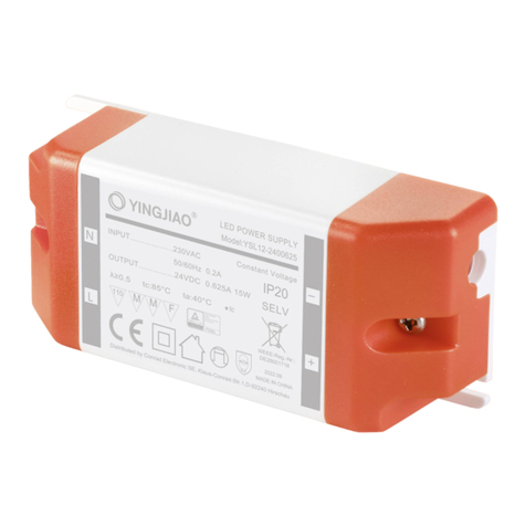
Radio receiver „FS20 EAM“
(for FS20 DIN rail system)
Item no. 62 30 12

2
Introduction
Dear customer,
Thank you for purchasing this product.
This product meets the requirements of both current European and national guidelines.
In order to preserve this condition and ensure the safe operation of the product we kindly ask
you to carefully follow these operating instructions!
Please read the operating instructions completely and observe the safety and operation notes
before using the product!
All company names and product names contained herein are trademarks of the
respective owners. All rights reserved.
Should you have any further questions, please contact our technical advisory service:
Germany: Tel. no.: +49 9604 / 40 88 80
Fax. no.: +49 9604 / 40 88 48
e-mail: [email protected]
Mon. to Thur. 8.00am to 4.30pm
Fri. 8.00am to 2.00pm

3
Table of contents
Page
1. Prescribed use ............................................................................................................... 4
2. Scope of delivery ........................................................................................................... 4
3. Explanation of icons ...................................................................................................... 5
4. Safety instructions ......................................................................................................... 5
5. Preparation .................................................................................................................... 7
6. Connection, installation, mounting ................................................................................ 7
a) General information ................................................................................................ 7
b) Using the supplied connector cable ...................................................................... 8
c) Using your own connection cable ........................................................................ 10
7. Information on the range ............................................................................................. 14
8. Handling ....................................................................................................................... 15
9. Maintenance and cleaning .......................................................................................... 15
10. Disposal ....................................................................................................................... 16
11. Technical specifications .............................................................................................. 16
12. Declaration of conformity (DOC) ................................................................................. 16

4
1. Prescribed use
The radio receiver ‘FS20 EAM’ is solely designed for operation using the ‘FS20 ESH’ power
supply (not supplied, please order separately).
It receives data from a wireless transmitter in the FS20 wireless control system and relays this
to the ‘FS20 ESH’ power supply. This amplifies the signals and transmits them via a 2-wire bus
to up to 36 actuators (for instance, ‘FS20 SH’ and ‘FS20 DH20’).
The radio receiver must be installed outside the switchboard/distributor in order to ensure good
radio reception.
There are two possible ways of connecting the ‘FS20 ESH’ power supply and the ‘FS20 EAM’
radio receiver:
• Connection via a standard, four-pole connection cable (supplied hardwired with the radio
receiver); the connector plug on the cable is plugged into the corresponding socket on the
front of the ‘FS20 ESH’ power supply
or
• Connection via own connector cable (two shielded wires or two twisted wire pairs), with a
maximum length of 3m; the connection uses the ‘FS20 ESH’ power supply’s A, B, C and
D screw terminals
Any use other than the one described above may damage the product and can also increase
the risk of short-circuit, fire, electric shock, etc.
No part of the product may be modified or adapted. The device may only be operated when
its casing is fully closed.
The safety instructions and installation notes in this user manual must be
observed without fail.
2. Scope of delivery
• Radio receiver ‘FS20 EAM’
• User manual

5
3. Explanation of icons
The icon with a lightning flash in a triangle is used to alert you to potential
personal injury hazards such as electric shock.
The icon with an exclamation mark in a triangle points to important instructions
in this user manual that must be observed.
The ‘hand’ symbol provides special information and advice on operating the
device.
4. Safety instructions
The product’s guarantee becomes invalid if the product is damaged as
a result of failure to observe these operating instructions. We do not
assume any liability for any resulting damages!
Nor do we assume liability for damage to property or personal injury
caused by improper use or failure to observe the safety instructions. In
such cases the product’s guarantee becomes invalid!
Dear customer, the following safety instructions are intended to protect you as well as
the device. Please take time to read through the following points:
• Only people who are appropriately trained are permitted to carry out work on
voltage-carrying parts. If you are not appropriately trained, please consult a
qualified electrician who is authorised to carry out such work.
• It may be necessary to make adjustments to the supply voltage or on live
voltage-carrying parts in order to connect the radio receiver.
Please observe the installation instructions when installing in distribution
systems. Interrupt the circuit current to all devices and power consumers
before opening the distributor housing and mounting and connecting the
‘FS20 EAM’ and any other components. There is risk of a fatal electric shock
if you touch live cables or parts!

6
Ensure that the supply voltage cannot be switched on by a third party while
this work is carried out. This can be done, for example, using mechanical
security fixtures and additionally using conspicuous warning signs.
• Do not use this product in hospitals or medical institutions. Although the
components of the FS20 wireless control system only emit relatively weak
radio signals, these may cause life-support systems to malfunction.
This may also be the case in other areas.
• Power and current must only be supplied by the ‘FS20 ESH’ power supply.
• The product may only be used in dry indoor areas. The radio receiver must
be installed outside the switchboard/distributor.
• Suitable, insulated wire-end sleeves must be used with multiple-wire con-
nections consisting of flexible installation cables! These should be crimped
on using an appropriate tool.
• For safety and licensing (CE) reasons any unauthorised alterations to and/
or modification of the product are not permitted.
• This product is not a toy. Devices operated via the supply voltage should be
kept out of the reach of children. Therefore, take particular care when
children are around.
• Do not leave packaging material lying around. This may become a danger-
ous plaything in the hands of children.
• The accident-prevention regulations, established by the Employer’s Liability
Insurance Association for electrical equipment and facilities, must be ad-
hered to in commercial facilities.
• Consult a skilled technician if you have doubts about the mode of operation,
safety or connection of the device.
• Handle the product with care; knocks, blows or even a fall from a low height
can damage it.

7
5. Preparation
Before assembling and using the device, make sure you take note of all the
safety and assembly instructions in this user manual.
Only people who are appropriately trained are permitted to carry out work on
voltage-carrying parts. If you are not appropriately trained, please consult a
qualified electrician who is authorised to carry out such work.
Any incorrect work carried out on the supply voltage may lead to a fatal electric
shock. Not only do you endanger your life, you also endanger the life of others!
When using flexible installation cables with multi-wire cores, insulated wire-
end sleeves (which must be crimped on with an appropriate tool) must be used.
The installation location is, amongst other things, determined by two important factors:
• The existing ‘FS20 ESH’ power supply
• Good radio reception for the ‘FS20 EAM’ receiver module
6. Connection, installation, mounting
a) General information
It is very important to observe the order of the following steps during
installation!
1. Before you open the switchboard or distributor and begin making alterations, switch off the
electrical circuits which supply power to these.
This is possible by either removing the fuse or turning off the automatic circuit breaker or
main fuse.
Make sure that no one switches the circuit on again by mistake whilst you are
temporarily away from your place of work (attach a warning on the building’s
distributor box).
Then test the relevant circuit to ensure that there is no longer current on it.

8
2. Mount the components of the FS20 DIN rail system, following the instructions in their
operating manuals.
3. Decide which of the two connection types you are going to use:
• Connection via a standard, four-pole connection cable (supplied hardwired with the
radio receiver); the connector plug on the cable is plugged into the corresponding socket
on the front of the ‘FS20 ESH’ power supply
or
• Connection via own connector cable (two shielded wires or two twisted wire pairs), with
a maximum length of 3m; the connection uses the ‘FS20 ESH’ power supply’s A, B, C
and D screw terminals
The procedure is described in precise detail in the following segments.
b) Using the supplied connector cable
The connector cable comes attached to the ‘FS20 EAM’ radio receiver. There is no need to
open up the radio receiver.
Proceed as follows:
• If you have not already done so, turn off the supply voltage to the switchboard/distributor,
see section 6. a) on page 9.
• Connect the four-pole plug on the connection cable of the ‘FS20 EAM’ radio receiver with
the corresponding socket on the front of the ‘FS20 ESH’ power supply, see figure 1.
Due to the special form of the plug, only one position is possible. Do not use
force when you are inserting it.

9
Connection for radio receivers
(via the cable supplied)
Figure 1: Connection for radio receivers
• Lay the connection cable at least 8mm away from voltage conducting cables or busbars.
The same applies to the radio receiver itself.
Otherwise there is the risk of a life-threatening electric shock!
• Use suitable fixing or mounting devices to fix the connection cables into place, for instance,
cable ties or adhesive pads.
• Install the ‘FS20 EAM’ radio receiver as far away as possible from metal surfaces or
voltage-carrying conductors so as not to affect the wireless range.
Hook-and-loop fasteners may be used to fasten the housing of the radio receiver into place.
This allows the radio receiver to be easily relocated if reception problems arise.
• Do not switch the supply voltage back on until the installation is completed.
Otherwise there is the risk of a life-threatening electric shock!
• The ‘FS20 EAM’ radio receiver’s LED screen illuminates to indicate readiness to receive
radio signals from the FS20 wireless control system.
• The individual components in the FS20 DIN rail system can now be programmed and then
operated using a FS20 wireless control system transmitter.
zu
FS20 EAM
FS20 ESH
A
1.3 B
1.7 C
2.3 D
2.7
DAT
2.4 GND
2.8

10
c) Using your own connection cable
If you wish to install radio receiver further away from the ‘FS20 ESH’ power supply, the supplied
cable may be removed and replaced by an up to 3m long cable.
This cable may either have two individually shielded wires or two twisted wire pairs.
Proceed as follows:
• If you have not already done so, turn off the supply voltage to the switchboard/distributor,
see section 6. a) on page 9.
• If the radio receiver is connected to the ‘FS20 ESH’ power supply via the hardwired cable,
remove the connector cable plug from the power supply socket.
• Open the housing of the ‘FS20 EAM’ radio receiver by removing the four fastening screws
with a suitable screw driver. Then carefully remove the cover of the housing.
Do not bend any of the circuit board components in the radio receiver
straight just so that it ‘looks better’!
1 yellow
2 green
3 brown
3 white
Figure 2
ANT
GND GND
+U B
ANT
GND GND
+U B
1
2
3
4

11
• Remove the screws on the screw terminal with a suitable screw driver and remove the
connector cable.
• Thread your cable through the cable grommet in the housing (see picture below) and screw
into place in the screw terminals.
Figure 3
1 To ‘FS20 ESH’, terminal A/B
2 To ‘FS20 ESH’, terminal C/D
3 Cable grommet
Flexible cables must have suitable insulated wire-end sleeves attached
before they are used. These should be crimped on with an appropriate tool
(around 8mm of cable should be stripped).
Make sure that the wires (outer conductors) protruding from shielded cables do
not come into contact with the neutral conductor, other contacts or the circuit
board (this could result in short-circuiting). For instance, using heat shrink
tubing.
• Lastly, attach the cables to the ‘FS20 ESH’ power supply.
Please take especial care that each cable is connected to the correct port.
Otherwise there is a risk that both the ‘FS20 EAM’ radio receiver and the
‘FS20 ESH’ power supply, as well as any other connected components,
will be destroyed!
The four wires should be connected using screw terminals ‘A’, ‘B’, ‘C’ and ‘D’
(follow the markings on the ‘FS20 ESH’ power supply).
ANT GND GND
+UB
FS20 ESH
(A/B)
ANT GND
FS20 ESH
(C/D)
+UBGND
©
12
3
ANT GND GND
+UB
FS20 ESH
(A/B)
ANT GND
FS20 ESH
(C/D)
+UBGND
12

12
Figure 4
• Lay the cables at least 8mm away from voltage-carrying cables or busbars. The same
applies to the radio receiver itself. Do not lay the cables parallel to power cables or busbars.
Otherwise there is the risk of a life-threatening electric shock!
Flexible cables must have suitable insulated wire-end sleeves attached
before they are used. These should be crimped on with an appropriate tool
(around 8mm of cable should be insulated, do not damage the wires!).
Make sure that the wires (outer conductor) protruding from insulated cables do
not come into contact with the neutral conductor or other contacts (this could
result in short-circuiting) For instance, using heat shrink tubing.
• The cables can be fastened using, for example, cable ties, adhesive pads or other suitable
fasteners.
• Once again check that the connection between the ‘FS20 EAM’ radio receiver and the
‘FS20 EAM’ power supply is laid correctly.
A
1.3 B
1.7 C
2.3 D
2.7
DAT
2.4 GND
2.8
+U
B
GND
FS20 EAM
ANT GND

13
If the wiring is incorrect, both the ‘FS20 EAM’ radio receiver and the ‘FS20
ESH’ power supply, as well as any other connected components, will be
destroyed!
• Close the radio receiver’s housing. Put the cover of the housing back onto the lower part
and screw them together.
• Install the radio receiver as far away as possible from metal surfaces or voltage carrying
conductors so as not to affect the wireless range.
Hook-and-loop fasteners may be used to fasten the housing of the radio receiver into place.
This allows the radio receiver to be easily relocated if reception problems arise.
• Do not switch the supply voltage back on until the installation is completed.
Otherwise there is the risk of a life-threatening electric shock!
• The ‘FS20 EAM’ radio receiver’s LED screen illuminates to indicate readiness to receive
radio signals from the FS20 wireless control system.
• The individual components in the FS20 DIN rail system can now be programmed and then
operated using a FS20 wireless control system transmitter.

14
7. Information on the range
Ranges and interference
• The FS20 wireless control system works in the 868MHz range, which is also used by other
radio services. Therefore devices that operate on the same or neighbouring frequency may
restrict both its operation and its range.
• The specified range of up to 100m is the free-field range, which means the range with visual
contact between the transmitter and receiver. In practice, however, walls, ceilings, etc.
between the transmitter and the receiver may affect and reduce the range.
• A repeater is available to increase the range of the FS20 wireless control system.
Other causes of reduced ranges:
• All types of high-frequency interference
• Any buildings or vegetation
• Conductive metal parts that are located near the devices or within or near their transmission
path, for example, radiators, metallised insulation glass windows, reinforced concrete
ceilings, etc.
• Influence on the radiation pattern of antennas due to the distance from the transmitter or
receiver to conductive surfaces or objects (also to human bodies or the ground)
• Broadband interference in urban areas that reduces the signal-to-noise ratio; the signal is
no longer recognised due to this ‘noise’
• Interference radiation resulting from insufficiently shielded electronic devices, for example,
operating computers or similar
Please note:
Do not position several radio receivers directly next to each other as these may
interfere with each other (minimum distance 0.2m, we recommend 0.5m or
more).

15
8. Handling
The product should only be used in dry indoor areas.
Make sure that the insulation of the entire product is neither damaged nor destroyed.
If damage is apparent, do NOT connect the product with the ‘FS20 ESH’
power supply! Life-threatening danger!
Avoid the following adverse ambient conditions at the installation location or during transport:
- Moisture or excessive air humidity
- Direct sunlight
- Extreme cold or heat
- Dust or flammable gases, vapours or solvents
- Strong vibrations
- Strong magnetic fields such as those found near machines or loudspeakers
9. Maintenance and cleaning
This product does not require maintenance.
In the case of a malfunction, any checks or repairs should be carried out by a skilled technician
or specialised professional workshop.
The outside of the radio receiver’s housing may be cleaned with a clean, soft, dry cloth.
Never use solvent-based cleaning agents, as these may damage the surface of the plastic
casing and its inscription.

16
10. Disposal
When the product is no longer usable, dispose of it in accordance with the
applicable statutory regulations.
11. Technical specifications
Operating voltage: .................... ‘FS20 ESH’ power supply specifications, 3.6V=
Reception frequency: ................ 868.35MHz
Range: ....................................... up to 100m (in free-field)
Dimensions: .............................. 70mm x 100mm x 24mm (W x H x D)
12. Declaration of conformity (DOC)
We, Conrad Electronic, Klaus-Conrad-Straße 1, D-92240 Hirschau (Germany), hereby de-
clare that this product complies with the fundamental requirements and other relevant
regulations of directive 1999/5/EG.
You can find the declaration of conformity for this product at www.conrad.com.

17

18

19

CONRAD IM INTERNET http://www.conrad.com
http://www.conrad.com
Imprint
These operating instructions are published by Conrad Electronic SE,
Klaus-Conrad-Str. 1, D-92240 Hirschau/Germany.
No reproduction (including translation) is permitted in whole or part e.g.
photocopy,microfilmingorstorage inelectronic dataprocessing equipment,
without the express written consent of the publisher.
The operating instructions reflect the current technical specifications at
time of print.We reserve the right to change the technical or physical
specifications.
© Copyright 2006 by Conrad Electronic SE. Printed in Germany.
100%
recycling
paper.
Bleached
without
chlorine.
Table of contents
Other Conrad Receiver manuals

Conrad
Conrad Eurosky SR 401 SAT User manual

Conrad
Conrad 2575392 User manual

Conrad
Conrad renkforce 1897728 User manual

Conrad
Conrad 67 87 44 User manual

Conrad
Conrad 97 36 82 User manual

Conrad
Conrad KK-C600 User manual

Conrad
Conrad Thermaltake EVO Blue User manual

Conrad
Conrad 20 53 62 User manual

Conrad
Conrad 1404311 User manual

Conrad
Conrad Akasa 91 89 12 User manual