Contrel EMM-mD3h User manual

EMM-µD3h EMM-µD3h-p EMM-µD3h-485 instruction manual IM380-U v3.1 pag. 1 / 12
INSTRUCTION MANUAL
IM380-U v3.1
EMM-µD3h DIGITAL MULTIFUNCTION METER FOR ELECTRICAL PARAMETERS
EMM-µD3h-p
EMM-µD3h-485
GENERAL
The digital multimeters series EMM-µD3h allow monitoring the main electrical parameters
present on adistribution line. The local display of the various electrical parameters is carried
out by 3displays with red LED, granting agood and simultaneous reading of various values. A
simple front panel completes the intuitive selection of several electrical parameters, in order to
provide full information.On top of the instantaneous measures, these instruments display the
maximums (peak of the main parameters and maximum demand or average maximum
value).The multifunction meters EMM-µD3h replace in aunique device, all the functions of
voltmeters, ammeters, energy meters, cosphimeters, wattmeter’s, varmeters, hour meters
and frequency meters. This gives agreat economic saving, by reducing space and time,
optimising also the purchase management of instruments, since one model meets most demanding requirements for local
measuring in electricalboards,switch-boards,MCC’s, Gen-sets,etc.
AVAILABLE TYPES
Among the large range of the EMM multimeters family, find here below the available EMM-µD3h types:
EMM-µD3h based version.
EMM-µD3h-p as EMM-µD3h version but with digital outputs for pulse emission or alarm signalling.
EMM-µD3h-485 as EMM-µD3h version but with RS485 port.
The auxiliary supply for all types, is available with following voltages:
- 230V (rated) 50-60Hz standard version
- 110V (rated) 50-60Hz optional version
- 400V (rated) 50-60Hz optional version
INTRODUCTION
The EMM-µD3h are only featured for local visualising the electrical parameters. The EMM-µD3h-p has two digital outputs.
The EMM-µD3h-485 has a RS485 port. The auxiliary supply is connected to 2 terminals, separated from the measuring
voltage inputs. It is necessary to use of external CT’s for measuring the currents.
ACCESSORIES AND OPTIONS
Accessories: Din rail mounting CT’s
Options: Auxiliary supply and measuring voltages, other than standard (under request)
Current Input 1A
Others CT secondary input (on request)
MEASURED PARAMETERS
Parameters
Measuring units
Identification symbols
phase and three phase voltage
[V]
V L1-N
V L2-N
V L3-N
V L-N
phase to phase and three phase system voltages
[V]
V L1-L2
V L2-L3
V L3-L1
V L-L
phase and three phase currents
[A]
I L1
I L2
I L3
I
phase and three phase power factors
PF L1
PF L2
PF L3
PF
phase and three phase active powers
[kW]
W L1
W L2
W L3
W
phase and three phase system reactive powers
[kVAr]
VAr L1
VAr L2
VAr L3
VAr
phase and three-phase system apparent powers
[kVA]
VA L1
VA L2
VA L3
VA
three phase average powers
[kW-kVAr-kVA]
W (avg)
VAr (avg)
VA (avg)
three phase forecasted average powers
[kW-kVAr-kVA]
W pr (avg)
VAr pr (avg)
VA pr (avg)
frequency
[Hz]
Hz L1
three phase active energy
[kWh]
kWh
three phase reactive energy
[kVArh]
kVArh
three phase apparent energy
[kVAh]
kVAh
hour meter
[h]
h
peak value (maximums):
phase voltage
[V]
V L1-N max
V L2-N max
V L3-N max
phase current
[A]
I L1 max
I L2 max
I L3 max
phase average current (maximum demand)
[A]
I L1 max (avg)
I L2 max (avg)
I L3 max (avg)
three phase system powers
[kW-kVAr-kVA]
W max
VAr max
VA max
three phase system average power (max demand)
[kW-kVAr-kVA]
W max (avg)
VAr max (avg)
VA max (avg)

EMM-µD3h EMM-µD3h-p EMM-µD3h-485 instruction manual IM380-U v3.1 pag. 2 / 12
INSTALLATION
WARNING FOR THE USER
Read carefully the instructions/indications contained in this manual before installing and using the instrument.
The instrument described in this manual is intended for use by properly trained staff only.
SAFETY
This instrument has been manufactured and tested in compliance with EN 61010-1 (IEC1010) standards. In order to maintain these
conditions and to ensure safe operation, the person must comply with the indications and markings contained in the manual. When
the instrument is received, before beginning installation, check that it's OK and it has not suffered any damage during transport. When
starting installations make sure that the operating voltage and mains voltages are compatible with the device instructions. The
instrument power supply must not be earthen. Only qualified and authorised personnel must carry out maintenance and/or repair. If
there is ever the suspicious that, that there is a lack of safety, during operation, the instrument must be disconnected and cautions
taken against accidental use.
Operation is no longer safe when: The instrument doesn't work. - There is clearly visible damage. - After serious damage
occurred during transport. - After a storage under unfavourable conditions.
The fixing to the DIN rail is granted by the rear spring fixing device.
It’s better to put an external protection with fuses for the voltage inputs and to use adapted cables for the working currents and
voltages: section from 0.5 to 4 mm2.
WIRING
For a correct use of the device, the wiring diagram contained in the
present manual must be respected. The connections are available
on the screw terminals:
- Power supply:
The auxiliary power supply is taken from the terminals aux1 and
aux2.
The rated supply voltages can be:
standard: Vn 230V ± 15% 50-60Hz
under request: Vn 110V ± 15% 50-60Hz
under request Vn 400V ± 15% 50-60Hz
- measuring voltage inputs:
4 terminals are available for wiring to the 3 phase and neutral of the
measuring network, the maximum voltage phase to phase shouldn't
be over 500V rms and 290V between phase and neutral.
In case of a 3-phase system without neutral or non-distributed
neutral, leave terminal N free.
For single phase use, wiring should be done between terminals L1
and N and bridge L2 and L3 phases to neutral N.
- measuring current inputs:
6 terminals are available for wiring to 3 external CT’s with secondary
5A, it’s possible to use 2 CT’s on 3 wires lines with (Aron three-
phase wiring) and the use of 1 CT in case of single phase system
(input IL1). External CT’s must always be used.
Don't connect CT's secondary to the earth.
The instrument’s SETUP menu allows to set the transformation rate
of the external CT and it’s possible to visualise readings of current
up 999 A. Should the case be that calculated current is higher than
the maximum value, the display will show the over range condition.
The maximum setting of the transformation ratio is 2000/5=400
NOTE: For a correct measuring of the power factor and energies and powers it's a must to respect the phase sequence. The
connections between current and voltage phase inputs must not be inverted (for example, CT placed on phase L1 must
correspond to the I1 input). So as it is not correct to invert S1 and S2 of the CT’s terminals.
VL3
VL2
VL1
N
aux1
aux2
IL3
IL2
IL1
Do2
Do1
Co
measuring voltage
inputs
max 500 V L-L
auxiliary
supply
110 or 230 or 400Vac
measuring current
inputs
max 5A options
S1
S2
S2
S2
S1
S1
c
A
B
RS485 serial port
2 X digital output
max 230Vac/dc 150mA
L1
L2
L3 L
VL-N
A
kW
kVAr
kVA
VL-L
...h
Hz/out
SET
P.F.
EMM-µD3
max
avg
VL1 VL2 VL3 N aux 2 aux 1
voltage inputs V aux
S1 S1 S1
S2 S2 S2 Do2
c
Co
B
Do1
A
IL1 IL2 IL3
currentinputs

EMM-µD3h EMM-µD3h-p EMM-µD3h-485 instruction manual IM380-U v3.1 pag. 3 / 12
WIRING DIAGRAMS
P1
S1
S1
S2
L1
L2
L3
THREE PHASE LINE WIRING WITH 3 WIRES AND 2 CT
(AARON Wiring)
P1 P2
S2
P2
LOAD
P1 P2
S1 S2
N
L
SINGLE PHASE WIRING
Should the case be that the instrument is used on single
phase, it has to be considered that the valid measures are
related to the phase L1, others realated to the three phase
system are not to be considered.
P1
P1
P1
P2
S1
S1
S1
S2
N
L1
L2
L3
IL2
IL1
IL3
S1
S2
VL1
VL2
VL3
N
measuringcurrent
inputs
measuring voltage
inputs
On three wires line (without neutral or with not
distribuited neutral) DON’T wire the N terminal.
WIRING IN A THREE PHASE LINE WITH 3 OR 4 WIRES
EMM
LOAD
aux1
aux2 auxiliary
supply
VL1
VL2
VL3
N
measuring voltage
inputs
EMM
aux1
aux2 auxiliary
supply
VL1
VL2
VL3
N
measuring voltage
inputs
EMM
aux1
aux2 auxiliary
supply
P1
S1
N
L1
L2
L3
VL1
VL2
VL3
N
measuring voltage
inputs
On three wires line (without neutral or with not
distribuited neutral) DON’T wire the N terminal.
BALANCED THREE PHASE LINE WIRING WITH
3 OR 4 WIRES
EMM
LOAD
aux1
aux2 auxiliary
supply
LOAD
S2
S1
S1
S2
IL2
IL1
IL3
S1
S2
measuringcurrent
inputs
S2
S1
S1
S2
IL2
IL1
IL3
S1
S2
measuringcurrent
inputs
S2
S1
S1
S2
IL2
IL1
IL3
S1
S2
measuringcurrent
inputs
S2
S1
S1
S2
RS485 Connection
EMM
aux1
aux2 auxiliary
supply
RS485
B ACOM
EMM
aux1
aux2 auxiliary
supply
RS485
B ACOM
Connection with shielded Connection with not shielded Digital Output connection
EMM
aux1
aux2 auxiliary
supply
Co DO1DO2

EMM-µD3h EMM-µD3h-p EMM-µD3h-485 instruction manual IM380-U v3.1 pag. 4 / 12
DESCRIPTION:
LEGEND:
A: Key for visualising the three phase system
parameters with its corresponding LED. By
pressing again this key, the instrument returns to
reading each individual phase. By keeping the
key pressed for 5 seconds the instrument
reaches the programming mode (SETUP). In
SETUP mode, this key confirms the values set
and by pressing the Bkey simultaneously, it
starts decreasing the value.
B: Key for selecting the measured parameters to be
shown at the Cdisplay. In SETUP mode selects
and modifies the value of the parameters to be
set.
A+B: With the simultaneous pressing of both keys the
instrument reaches the visualisation of the
maximum and average values, which may be
selected with the Bkey. To escape from
maximum and average values visualisation, don’t
press any key for 8 seconds.
C: Three displays for visualising the measures,
subdivided by phase of the parameters indicated
by the LED Dbar. In case that the LLED (G) is
glowing, the instruments shows the three phase values of the measures, indicated by the LED Dbar.
D: LED bar for indicating the measures visualised on display C.
E: Terminals for wiring the voltage measures input and auxiliary supply.
F: Terminals for wiring the current measures input and the digital output (when present in the instrument).
G: LED for indicating of a three phase value visualisation.
MENU FOR PROGRAMMING THE INSTRUMENT (SETUP)
The instrument’s SETUP menu is reached by pressing the Akey during 3 seconds. Once in the SETUP menu, it is
possible to select or modify the visualised parameter’s value, by pressing the Bkey.
If no pressing is made on any key during 8 seconds, the instrument escapes from the SETUP menu.
For a correct operation of the multimeters the instrument has to be programmed with the transformation ratio of the
external CT’s.
It will only be possible to reset the energy meters in those instruments fitted with such a characteristic, so as to program
the digital outputs only if the digital outputs is available in the instruments.
The set values are kept without auxiliary supply even.
> 5 seconds, access to the programming menu (SETUP)
for selecting of a parameter or modifying the parameter’s value for programming (SELECT)
for confirming the selection or confirming the programmed parameter’s value (ENTER)
L
SET
L
SET
C
E
F
L1
L2
L3 L
VL-N
A
kW
kVAr
kVA
VL-L
...h
Hz/out
SET
P.F.
electrical m ulti m eter
EMM-µD3
max
avg
VL1 VL2 VL3 N aux2 aux1
voltage inputs V aux
S1 S1 S1
S2 S2 S2 Do2
c
Co
B
Do1
A
IL1 IL2 IL3
currentinputs
A
B
D
G

EMM-µD3h EMM-µD3h-p EMM-µD3h-485 instruction manual IM380-U v3.1 pag. 5 / 12
CONFIGURATION OF GENERAL PARAMETERS ( )
Entry to menu:
(only for EMM-µD3h-p)
Increase
Set CT ratio
from to Decrease
Increase
Set VT ratio
from to Decrease
Increase
Set average time
from to minutes Decrease
Set connection
type
Set wiring connection
type
Set synchronism
type
(only for EMM-µD3h-p) kWh-kVAr / pulse
Set pulse weight kWh-kVAr / pulse
kWh-kVAr / pulse
kWh-kVAr / pulse
(only for EMM-µD3h-p) Increase
from to mS
in step by 100 mS Decrease
(only for EMM-µD3h-485) Increase
Set address of network
from to Decrease
Set baud rate 19200 baud
serial interface 9600 baud
(only for EMM-µD3h-485) 4800 baud
2400 baud
Set parameters of bit: 8data 1stop-no parity
Communication bit: 8data 2stop-no parity
serial interface bit: 8data 1stop-even parity
(only for EMM-µD3h-485) bit: 8data 1stop-odd parity
Increase
Set Password
÷ Decrease
Confirm and end of general settings

EMM-µD3h EMM-µD3h-p EMM-µD3h-485 instruction manual IM380-U v3.1 pag. 6 / 12
Programming the transformation ratio of the external CT’s ( )
The programming of the CT’s ratio is considered as the rate between the primary and the secondary (i.e.: with CT 1000/5,
we must set 200 as value). The setting will be done with the push-button on the front panel.
Some seconds after giving the auxiliary supply to the instrument (during the switching on, all LED and displays will flash
alternatively to the firmware indication), by pressing the Akey, the display Cwill show the message .
Then press Aagain to reach the programming menu and the Cdisplay will show the message and the value of
the transformation ratio (set as 1 by the manufacturer) will appear at the third display. Press the Bkey to increase the
value or press simultaneously the Akey to decrease the value (the variation is performed unit per unit). To speed up the
operation, keep on pressing the button Aand B, and the variation will appear successively by tens and hundreds,
releasing and pressing the key again it will return to increase or decrease the value at unit per unit. Press the Akey to
confirm, the instrument will pass to successive programming menu. Shouldn’t any key be pressed during a 10 seconds
interval of time, the instrument will exit automatically from programming without saving the set values.
Programming of the transformation ratio of the external voltage transformers
After the precedent programming phase, on Edisplay will appear the inscription (voltage transformer) and the value of
the transformation rate of the external TV (set to 1 from the constructor), considered as the rate between primary and
secondary (example with TV 15/0.1 kV the value will be 150).
In the same way at the programming of the CT rate will be possible to set this value. If the external TV are not used the
value to set will be 1. To confirm the value press the Abutton.
Programming of the average time ( )
After the programming phase previously described, pressing another time the Akey, on the Cdisplay will appear the
message and the average time settable from 1 to 30 minutes.
ToincreasethevaluepresstheBkey.Todecreaseit,presstheAkeywithBkeyalreadypressed.ToconfirmitpresstheAkey.
The average time is the time used to calculate the average parameters (avg) and the maximum demand (maxD).
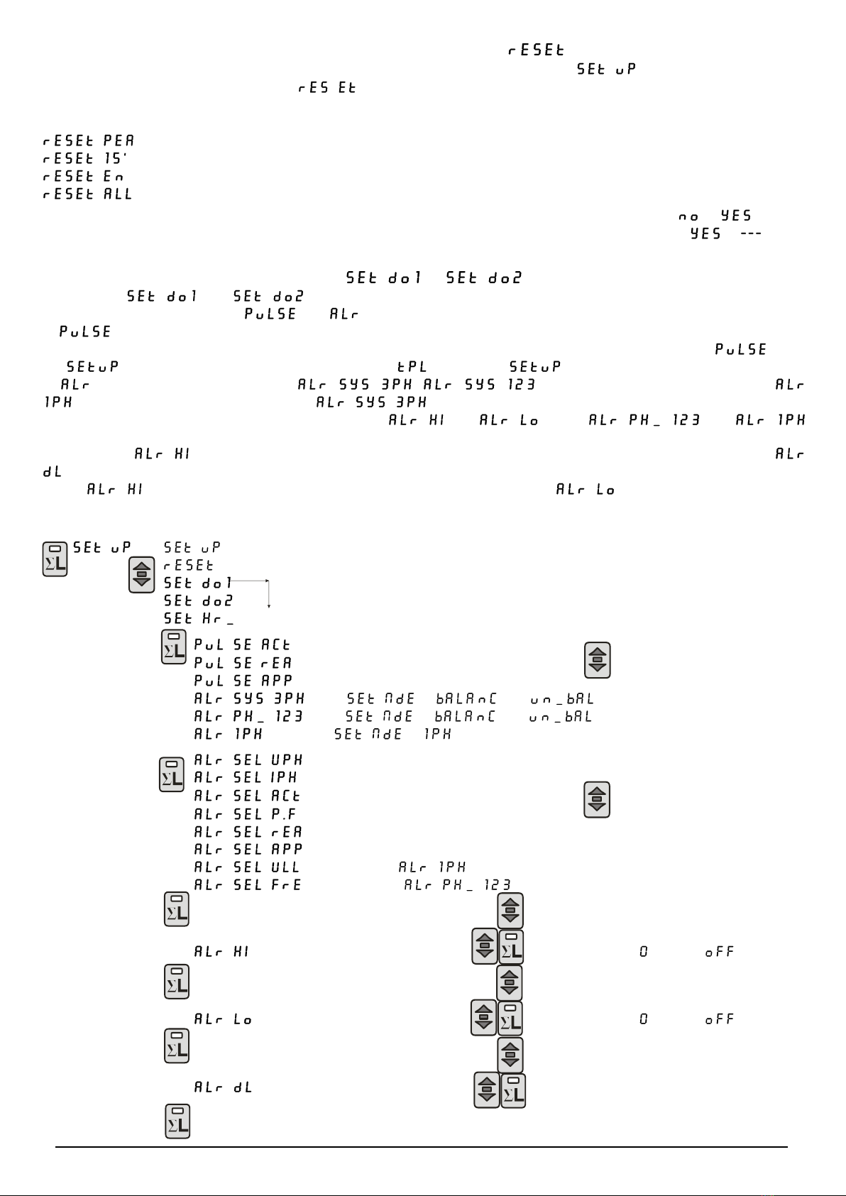
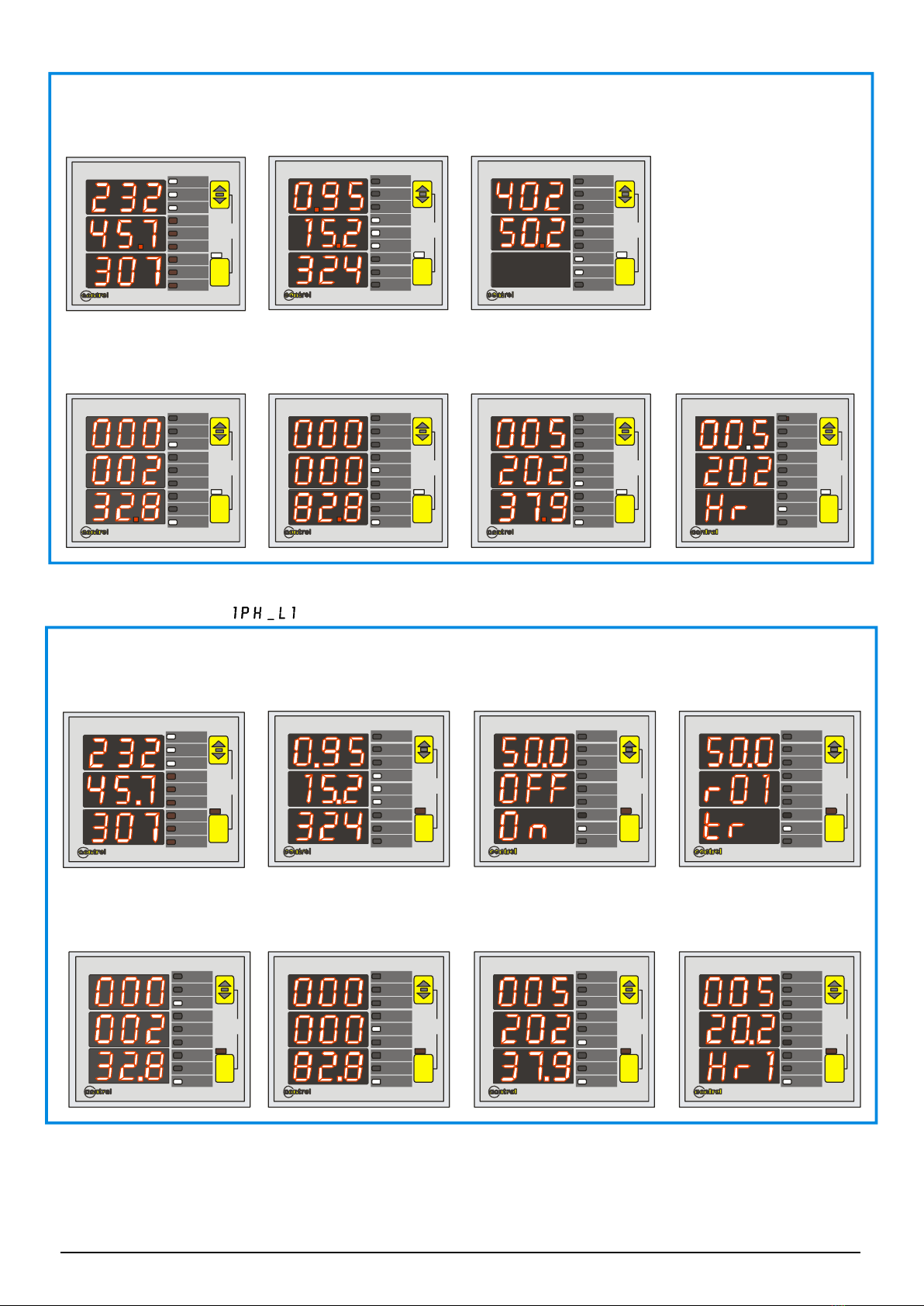
Programming insertion mode ( )
In aunbalance three phase system it’s necessary to set (unbalance) while in abalance system (only one CT
and only one VT) the correct set is (balance). For asingle phase insertion it’s necessary to set .
Programming wiring connection mode ( )
This setting allows to definite the wiring type connection. It’s possible to chose 3 wires or 4 wires. With the 4 wires
connection the neutral parameter are displayed and enabled to use for the digital outputs settings.
Programming of the synchronism type ( )
In this setting for the synchronization type, it’s possible to choose to use the external frequency (on L1 phase) or ,
Hz to use the internal clock.
Programming the weight of the energy pulses ( ) (onlyfor EMM-µD3h-p)
After the previously described programming step, and pressing the Akey, the Cdisplay will show message and
the weight value of each single pulse, settable between 4 values: - - - .
For each emitted pulse, the instrument had counted 0,01 - 0,1 - 1 - 10 kWh , kVArh, kVAh according with what it has been
selected in the digital output configuration. Press the Bkey to modify the value in the cyclic mode. Confirm the
configuration by pressing the Akey.
Programming the pulse duration ( ) (only for EMM-µD3h-p)
The message will appear together with the pulse duration value, expressed in mS. It is possible to select the value
between 100 mS and 500 mS, in 100 mS steps. Press the Bkey to modify the value in the cyclic mode. Confirm the
configuration by pressing the Akey.
Programming of the address for the communication network ( ) (only for EMM-µD3h-485)
After the confirm with the Akey of the previous value, the message will appear on Cdisplay; to set the value
that will identify the instrument when it will be connected in a EIA485 communication network, proceed with the modality,
already described. The settable values are from 1 to 247. To confirm, press the Akey.
Programming of the baud rate ( ) (only for EMM-µD3h-485)
The following setting is the baud rate. The message on the first two parts of Cdisplay to indicate the
programming of the baud rate displayed on the third part (L3) ofthe Cdisplay. To modify the value set, it’s necessary to
use the Bkey. The values settable are: => 19200 baud, =>9600 baud, =>4800 baud, =>2400
baud. Press Ato confirm the value displayed.
Programming of the serial parameters (only for EMM-µD3h-485)
The following message will appear on Cdisplay using the Bkey. To confirm press the Akey.
8 data bit / 1 stop bit
No parity
8 data bit / 2 stop bit
No parity
8 data bit / 1 stop bit
Even parity
8 data bit / 1 stop bit
Odd parity
Programming of the Password ( )
The instrument is supplied without password. When apassword (from 0002 to 9999) is set, using the B(to increase), A-B
together (to decrease) and A(to confirm) keys, only who know this value can to enter in the setup. The password, in fact, is
requiredallthetimethatsomeonetrytoenter inthesetup(pressingtheAkeyformoreof 3seconds).Ifthepasswordiswrong,
the message will appear on Cdisplay and the instrument go back to the measures visualization. To input the
password,whenrequiredbytheinstrument,attheenterofthesetup,usetheAandBkeysasthesamewaydonepreviously.

EMM-µD3h EMM-µD3h-p EMM-µD3h-485 instruction manual IM380-U v3.1 pag. 7 / 12
CANCELLING OF THE PEAK VALUES AND ENERGY METERS ( )
From the measures visualisation mode, keep the Akey pressed until the message appears on the Cdisplay;
then press the Bkey until the message appears on the Cdisplay; access to the reset menu by pressing the A
key. By pressing the same key we can now select the cancellation type that we wish to activate.
Here below the different types:
cancellation of the instantaneous values only
cancellation of the average values in the 15’ only
cancellation of the energy meters
cancellation of the energy meters, average and the instantaneous values.
To activate the selected cancellation mode, press the Bkey to change the Cdisplay’s indication from to .
Confirm to activate the cancellation, by pressing the Akey; the indication in the display Cwill pass from to
Without pressing any key, wait until the instrument returns to the measures visualisation mode.
PROGRAMMING THE DIGITAL OUTPUT ( ) (only for EMM-µD3h-p)
In the menu and it’s possible to program the function of all digital outputs. In these menus are
available the following modality: and (alarm).
In mode the digital output DO1 will emit pulses proportional to the active energy counted while the digital output
DO2 will emit pulses proportional to the reactive energy counted. The proportionality will depend from the set in
the and the duration of the impulse is set in the voice of the .
In mode there are three settings , for the three-phase connection and
for the single phase connection. With the digital output works as alarm verifying that the (average)
three-phase value doesn’t exceed the thresholds set ( and ). With and
the digital output works as alarm verifying that the maximum value of the single phase doesn’t exceed the maximum
threshold set ( ) and that the minimum value of the single phase is below the minimum threshold set. With
it’s possible to activate the digital output after a delay expressed in seconds.
If only threshold is set, alarm act as “maximum value” function; If only threshold is set, alarm act as
“minimum value” function; if both thresholds are set, alarm works as “BAND” function.
Access to the menu:
Selecting the pulse type
or alarm
(with = and )
(with = and )
(only with = )
Selecting the alarm
parameter
(see list)
(not usable for )
(not usable for )
Set maximum alarm threshold Increase
Decrease (after there is )
Set minimum alarm threshold Increase
Decrease (after there is )
Set delay Increase
Decrease
Confirm and end of digital output configuration.

EMM-µD3h EMM-µD3h-p EMM-µD3h-485 instruction manual IM380-U v3.1 pag. 8 / 12
ENTER IN THE SETUP
To program the digital output from the measures visualization, keep pressed the Akey (5 seconds), the message
will appear on the Cdisplay.
CHOOSE THE DIGITAL OUTPUT SETTING
Press repeatedly the Bkey until the message or appears on the Cdisplay. Press the Akey to
select this setting.
SELECT THE MODALITY OF FUNCTIONING OF THE DIGITAL OUTPUT
To select the functioning mode, using the Bkey, it’s possible to select: , , .
(pulse emission) with DO1 linked to (active energy) parameter and DO2 linked to (reactive energy)
parameter; , (alarm on three phase value), (alarm on minimum and maximum single
phase value) and in a three-phase or in a balanced three-phase connection with connection mode set on or
; alarm on the minimum value and maximum value of L1 phase in a single-phase connection with
connection mode set to . Confirm the setting, pressing the AKey.
CHOOSE THE PARAMETER TO LINK TO THE DIGITAL OUTPUTS
With an alarm modality set, it’s necessary to select the parameters associated to the alarm output; by pressing the Bkey
until the parameter choice appears on the third part (L3) of Cdisplay and the glowing the corresponding led on the Dbar.
Press Akey to confirm the set.
SET THE HIGH AND THE LOW THRESHOLDS
On Cdisplay will appear the message with the high threshold value; confirming with the Akey on the same display
will appear the message with low threshold value. The high and the low thresholds values are set using the Bkey
to increase the values, and Aand Bkey pressed together (starting from the condition Bkey pressed) to decrease the
values. The range depends by the parameter and it is linked to the CT and VT ratios. Pressing Akey to confirm.
The threshold set is linked with CT and VT ratios, for this reason it’s necessary to make this operation after the
programming of the CT and VT. The end scale value must be confirmed when CT and VT ratios are modified.
The low threshold will be lower than high threshold. If the high threshold is set as OFF the low threshold will have the
range of the high threshold.
SET THE DELAY TO THE DIGITAL OUTPUT ACTIVATION
Now it’s possible to set the delay that will pass between the alarm condition set and the activation of digital output. On C
display will appear and the value expressed in seconds (range 1÷900). The modification of the value is done in
the same way of the threshold set. With the confirmation (Akey) the set is complete.
PROGRAMMING OF THE HOURS COUNTER ( )
The hour counter will be increased when the measure of the parameter will exceed the set threshold value.
(the visualization depends on the settings and the I/O status)
To chose the parameter
(see the variable list)
Set the threshold Increase
Decrease
Confirm and end of hour counter settings.
SELECT THE PARAMETER TO LINK TO THE HOURS COUNTER
From the previous setting, pressing the Ckey it’s possible to set the hours counter: the message appears on
the Fdisplay. Press the Akey to define the parameter to link to the hours counter. Press more time the Bkey to select the
parameter and the Akey to confirm it.
SET THE THRESHOLD
Subsequently it’s necessary to set the threshold using the B(to increase) and C(to decrease) keys. Confirm with Akey.
VARIABLE LIST
three-phase voltage reactive power
three-phase current apparent power
three-phase power factor phase to phase voltage
active power frequency

EMM-µD3h EMM-µD3h-p EMM-µD3h-485 instruction manual IM380-U v3.1 pag. 9 / 12
MEASURES VISUALISATION
According with the glowing status of the GLED the reading of the measures is visualised on display C, either the three
measures of the phase values or the three phase measured values (average of the individual phases for voltage,
current, power factor and the sum of the individual phases for powers).
With the GLED off, the instrument will visualise the three measures of phase (L1, L2 and L3 respectively) of the
parameter indicated by the light of the LED D. for the phase to phase measures (V L-L), the three measures are
understood V L1-L2, V L2-L3, V L3-L1 respectively.
By pressing the Bkey, you may select the parameters to visualise, which will be indicated by the LED D.
The visualisation of the frequency page shows also the status of the digital output (if present).
By pressing the Akey with the GLED on, the instrument will visualise the selected parameters in three phase values
(average of the individual phases for voltage, current, power factor and the sum of the individual phases for powers).
In this mode, each page will show the measures of 3 parameters, indicated by the LED D, excluding the frequency pages,
the energy meters and the hour meters.
The visualising of the energy meters is only possible with the GLED on.
If the hour meter is available, is visualised: as hour meter per phase, activated by the three phase current, after the
visualisation of energies in those types fitted with energy meters.
By pressing the same key again, the instrument returns to the visualisation of the phase parameters.
Should the single phase system wiring been made, the visualisation of the values will be shown in the same way as per
the three phase measures, indicating three parameters on each page. In the present case the LED Gwill never glow,
since it isn’t a three phase system.
VISUALISATION OF ENERGY AND HOUR METERS
The visualisation of the energy meters are shown with the lighting of the LED kW + …h indicating the active energy values
(kWh), whilst the lighting of the LED kVAr + …h are indicating the reactive energy values (kVArh).
The lighting of the LED h alone, identifies the reading of the hour meter.
The reading of the meters uses the 9 digits (maximum reading 99999999.9) of the display C: the measure comes
visualised in such a way that, the display L1 will show the first 3 digits, the display L2 the second 3 digits and the display
L3 the last 3.
For example if: L1=000, L2=028, L3=53.2, the reading is equal to 00002853.2 kWh.
In the case of the hour meter, it uses only 6 digits (maximum reading 99999,9) of the display C: the measure comes
visualised in such a way that, the display L2 will show the first 3 digits, and the display L3 the last 3 digits .
For example if: L2=008, L3=53.2 the reading is equal to 00853.2 h.
NOTE ON THE VISUALISATION OF THE PARAMETERS
The visualisation of a capacitive power factor value comes represented by a –sign before the first digit of the display
(example of reading: indicates a capacitive power factor of )
The visualisation of a negative active power (inverted connection of the CT’s or cogeneration presence) comes
represented by a –sign before the first digit of the display.
VISUALIZATION OF THE PHASE VALUES (for three-phase connection)
(connection mode set to or )
L1
L2
L3 L
out
max
avg
SET
Visualization page 1
VL1-N on L1 = 232 V
VL2-N on L2 = 230 V
VL3-N on L3 = 229 V
L1
L2
L3 L
out
max
avg
SET
Visualization page 2
IL1 L1 = 28,2A
IL2 on
on L2 = 9,2 A
IL3 on L3 = 35,7A
L1
L2
L3 L
out
max
avg
SET
Visualization page 3
PL1 on L1 = 562 kW
PL2
on L2 = 184 kW
PL3 on L3 = 99,2 kW
L1
L2
L3 L
out
max
avg
SET
Visualization page 5
QL1 L1 = 562 kVAr
QL2 on
on L2 = 184 kVAr
QL3 on L3 = 99,2 kVAr
L1
L2
L3 L
out
max
avg
SET
Visualization page 6
SL1 L1 = 562 kVA
SL2 on
on L2 = 184 kVA
SL3 on L3 = 99,2 kVA
L1
L2
L3 L
out
max
avg
SET
Visualization page 7
VL1-L2 = 401 V
VL2-L3 = 403 V
VL1-L3 = 399 V
L
out
max
avg
SET
L1
L2
L3
Visualization page 8
F on L1 = 49,9 Hz
Out = ON
Dig. Out = Alarm
L1
L2
L3 L
out
max
avg
SET
Visualization page 4
PF on L1 = 0,93
PF
on L2 = 0,92
PF on L3 = 0,90

EMM-µD3h EMM-µD3h-p EMM-µD3h-485 instruction manual IM380-U v3.1 pag. 10 / 12
VISUALIZATION OF THE THREE PHASE VALUES
VISUALIZATION OF THE SINGLE PHASE VALUES
(connection mode set to )
L1
L2
L3 L
EMM-µD3 electrical multi meter
VL-N
A
kW
kVAr
kVA
VL-L
...h
Hz/out
max
avg
SET
P.F.
L1
L2
L3 L
EMM-µD3 electrical multi meter
VL-N
A
kW
kVAr
kVA
VL-L
...h
Hz/out
max
avg
SET
P.F.
Visualization page 1
VL-N onL1
IL on L2
kW on L3
Visualization page 4
Three PhaseActive Energy
counted
232,8 kWhr
L1
L2
L3 L
EMM-µD3 electrical multi meter
VL-N
A
kW
kVAr
kVA
VL-L
...h
Hz/out
max
avg
SET
P.F.
L1
L2
L3 L
EMM-µD3 electrical multi meter
VL-N
A
kW
kVAr
kVA
VL-L
...h
Hz/out
max
avg
SET
P.F.
Visualization page 2
PF L1on
kVAr on L2
kVA on L3
Visualization page 5
Three PhaseReactive Energy
counted
82,8 kVArhr
L1
L2
L3 L
EMM-µD3 electrical multi meter
VL-N
A
kW
kVAr
kVA
VL-L
...h
Hz/out
max
avg
SET
P.F.
L1
L2
L3 L
EMM-µD3 electrical multi meter
VL-N
A
kW
kVAr
kVA
VL-L
...h
Hz/out
max
avg
SET
P.F.
Visualization page 3
VL-L on L1
Freq. onL2
Visualization page 6
Three PhaseApparent Energy
counted
520237.9 kVAhr
L
VL-N
A
kW
kVAr
kVA
VL-L
...h
Hz/out
max
avg
SET
P.F.
L1
L2
L3
EMM-µD3 electrical multi meter
Visualization page 7
Three Phase
Hour counter
520.2 h
L1
L2
L3 L
EMM-µD3 electrical multi meter
VL-N
A
kW
kVAr
kVA
VL-L
...h
Hz/out
max
avg
SET
P.F.
Visualization page 1
VL1-N L1on
IL1 on L2
kWL1 on L3
L1
L2
L3 L
EMM-µD3 electrical multi meter
VL-N
A
kW
kVAr
kVA
VL-L
...h
Hz/out
max
avg
SET
P.F.
Visualization page 4
Active Energy counted
phase
232,8 kWhr
L1
L1
L2
L3 L
EMM-µD3 electrical multi meter
VL-N
A
kW
kVAr
kVA
VL-L
...h
Hz/out
max
avg
SET
P.F.
Visualization page 2
PFL1 L1on
kVArL1 on L2
kVAL1 on L3
L1
L2
L3 L
EMM-µD3 electrical multi meter
VL-N
A
kW
kVAr
kVA
VL-L
...h
Hz/out
max
avg
SET
P.F.
Visualization page 3
for EMM-µD3h-p
Freq. phase L1
Digital Output 1 Status onL2
Digital Output 1 Status on L3
L1
L2
L3 L
EMM-µD3 electrical multi meter
VL-N
A
kW
kVAr
kVA
VL-L
...h
Hz/out
max
avg
SET
P.F.
Visualization page 5
Reactive Energy counted
L1 phase
82,8 kVArhr
L1
L2
L3 L
EMM-µD3 electrical multi meter
VL-N
A
kW
kVAr
kVA
VL-L
...h
Hz/out
max
avg
SET
P.F.
Visualization page 6
Apparent
L1 Energy counted
phase
520237.9 kVAhr
L1
L2
L3 L
EMM-µD3 electrical multi meter
VL-N
A
kW
kVAr
kVA
VL-L
...h
Hz/out
max
avg
SET
P.F.
Visualization page 7
Hour counter L1 phase
00520.2 h
L1
L2
L3 L
EMM-µD3 electrical multi meter
VL-N
A
kW
kVAr
kVA
VL-L
...h
Hz/out
max
avg
SET
P.F.
Visualization page 3
for EMM-µD3h-485
Freq. phase L1
Address on L2
Transmission status onL3

EMM-µD3h EMM-µD3h-p EMM-µD3h-485 instruction manual IM380-U v3.1 pag. 11 / 12
VISUALISATION PEAK VALUES (MAXIMUM) INSTANTANEUS AND AVERAGE.
By pressing the Aand Bkeys simultaneously the instrument reaches the visualisation of the peak value (maximum): the
visualised measures selectable by Bkey, they will start flashing alternatively with the indication of the type of the maximum
value.
The maximum memorised values are of two types: the maximum instantaneous values, memorise the maximum reached
value of the measured parameter, during at least 1 second, the indicated value will flash alternatively with the message
(peak); the average values memorise the average value reached, during the last , of the measured
parameter, the value will flash alternatively with the message (AVeraGe).
The integration for the calculation of the values is synchronised at every switch on of the instrument
The maximum values, which may be selected with the Bkey are the following:
THREE-PHASE SYSTEM
parameter
Identification symbol
Value type
phase voltage
V L1-N max
V L2-N max
V L3-N max
phase current
I L1 max
I L2 max
I L3 max
average phase current (maximum demand)
I L1 max (avg)
I L2 max (avg)
I L3 max (avg)
three phase system powers
W max
VAr max
VA max
average three-phase system powers (maximum demand)
W max (avg)
VAr max (avg)
VA max (avg)
three phase system average powers
W (avg)
VAr (avg)
VA (avg)
SINGLE PHASE SYSTEM
Parameter
Identification symbol
Value type
maximum phase voltage
V L1-N max
maximum phase current
I L1 max
maximum phase powers
W max
VAr max
VA max
average phase current (maximum demand)
I L1 max (avg)
average phase powers (maxiimum demand)
W max (avg)
VAr max (avg)
VA max (avg)
average phase powers
W (avg)
VAr (avg)
VA (avg)
NOTE relative to measures.
The refresh time of the displays is below 1 second, with a comfortable reading of the measures, even in presence of sudden variations
of the measured parameters.
In case that the indicated measures aren’t reliable or they are absurd, it’s important to check carefully the current and voltage inputs
connection, so as the phase sequence. Check that current and voltage correspond to the same phase (on input L1 it will be connected
phase voltage L1 and the CT will be placed on phase L1), thence terminal S1 of CT will be wired to the relative terminal S1 on the
instrument.

EMM-µD3h EMM-µD3h-p EMM-µD3h-485 instruction manual IM380-U v3.1 pag. 12 / 12
TECHNICAL CHARACTERISTICS
MEASURES AND ACCURACY
Voltage
True rms value of the phases voltages and phase to phase in a three phase system
Total range of measure: 20÷500V trms phase to phase- 380V rms phase-neutral –40÷100Hz
Visualization (20,0÷500V) - measure accuracy: ±0,5% ±1 digit –maximum values management
Current
True rms value of phase currents and three phase system value
Range of measure: 0,02÷5A trms digit –40÷100Hz
Visualization 0,02÷999A - accuracy: ±0,5% ±1- average and maximum values management
Frequency
Frequency of phase L1 –measuring range: 30÷500Hz
Accuracy: ±0,5% ±1 digit
Powers
Active, reactive and apparent powers of phase and three phase system
Range of measure: 0,01÷999kW - 0,01÷999kVAr - 0,01÷999kVA
Accuracy: ±1% ±1 digit - Maximum, average and instantaneous values management
Power factor
Phase and three phase power factor
Range of measure: -0,1÷0,1 / accuracy: ±1% ±1 digit - Maximum and average values management
Hour meter
Time metering in hours and decimal of hours
Range of measure 0,0 ÷ 99999.9 h / accuracy ±0,5%
Energy measures
Active, reactive and apparent energies of the three phase system
Range of measure: 0÷99999999,9 kWh / kVArh / kVAh class 1 (EN 62053-21) accuracy: ±1%
AUXILIARY POWER SUPPLY AND INPUTS
Auxiliary supply
Standard 230V ±15% - optional 110V or 400V ±15% - 50-60Hz - max 3VA
Voltage inputs
From 20 to 500V phase-phase; permanent overload +20% - input impedance: 1 M
3, 4 and single phase wiring
Current inputs
From 0,02 to 5A; permanent overload 50% - from external CT’s with secondary 5A (optional 1A),
Primary programmable from 5 to 2000A - self-consumption <0,5VA
INPUTS / OUTPUTS
Digital outputs
(only for EMM-µD3h-p)
Digital output ON-OFF(opto-isolated), 5÷230V ac/dc, max 150mA - insulation: 3kV for 60 seconds
Proportional pulse emission to the active and reactive energy:
DO1: active energy pulse output
DO2: reactive energy pulse output
Programmable pulse weight 0,01-0,1-1-10 kWh/pulse, pulse duration 100÷500 msec, max frequency 5Hz
Alarm signalling function: Setting of measured parameter and time to trip delay 1 ÷ 900 sec
serial output
(onlyfor EMM-µD3h-485)
One output RS485, baud rate selectable, MODBUS-RTU protocol, baud rate 4800÷19200
insulation: 3kV for 60 seconds
GENERAL
Display, keys
3 display with red LED 7,5mm each of 3 digits 7 segments
2 keys for selecting measures and programming , LED bar 10 points
Mechanical
Protection degree: IP52 front - IP20 enclosure and terminals - weight: 0,3 kg approx.
Screw wiring terminal for maximum cross section cable of 4 mm2
Self- extinguishing plastic enclosure –for DIN rail mounting, 3 modules of 17,5mm
Environment
Workingtemperature:-10÷60°C;humidity<95%-Storingtemperature:-25÷70°C-Isolationtest:3kVfor1min.
Standards of reference
EN 61326-1; EN 55022; EN 61000-6-2; EN 61000-6-4; EN 61010-1; EN 62053-21
DIMENSIONS
90
modular version 35mm
DIN 50022
3 moduls 17,5 mm
52.5 60
55
44
45
L1
L2
L3 L
out
SET
electrical multi meter
EMM-µD3
max
avg
VL1 VL2 VL3 N aux2 aux1
voltage inputs V aux
S1 S1 S1S2 S2 S2 Do2
c
Co
B
Do1
A
IL1 IL2 IL3
current inputs
This manual suits for next models
2
Table of contents
Other Contrel Multimeter manuals