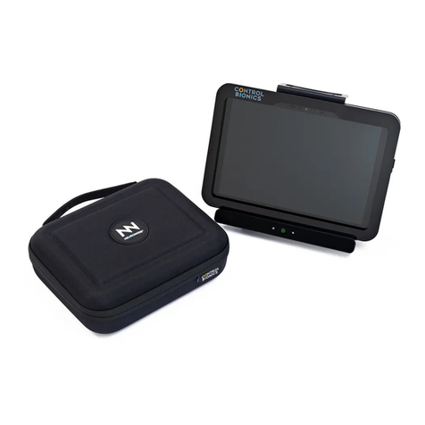
Control Bionics NeuroNode 3 User manual

NEURONODE3
USER GUIDE
Client Support
USA: (513) 453-4848
AUS: (03) 9897-3576

This page is intentionally left blank.

Catalog Number: 27-3500
User Guide, Revision E
Address comments, questions, or requests pertaining to this manual to:
Control Bionics US: (513) 453-4848
745 Center Street, Suite 303 US Toll-free: (855) 831-7521
Milford, Ohio 45150 US Fax: (513) 322-4678
www.controlbionics.com AUS: +61 3 9897 3576
neuronode@controlbionics.com
The NeuroNode is listed and registered with the FDA as a Powered Communication System and
a Powered Environmental Control System and certified by the Australian Government Depart-
ment of Health Therapeutic Goods Administration.
Copyright 2006 - 2019 Control Bionics Inc. All Rights Reserved.
NeuroEDUCATOR® and NeuroNode® are trademarks of Control Bionics Inc.
Anatomic images©CLIPAREA l Custom media/Shutterstock.
All other trademarks are the property of their respective owners.
Product design and specifications may be changed without notice.
Patent Pending.

Catalog Number: 27-3500
User Guide, Revision E
This device complies with part 15 of the FCC Rules. Operation is subject to the following two
conditions: (1) This device may not cause harmful interference, and (2) this device must accept
any interference received, including interference that may cause undesired operation.
NOTE: This equipment has been tested and found to comply with the limits for a Class B digital
device, pursuant to part 15 of the FCC Rules. These limits are designed to provide reasonable
protection against harmful interference in a residential installation. This equipment generates,
uses and can radiate radio frequency energy and, if not installed and used in accordance with
the instructions, may cause harmful interference to radio communications. However, there is no
guarantee that interference will not occur in a particular installation. If this equipment does
cause harmful interference to radio or television reception, which can be determined by turning
the equipment off and on, the user is encouraged to try to correct the interference by one or
more of the following measures:
• Reorient or relocate the receiving antenna.
• Increase the separation between the equipment and receiver.
• Connect the equipment into an outlet on a circuit different from that to which the receiver is
connected.
• Consult the dealer or an experienced radio/TV technician for help.
This device complies with Industry Canada licence-exempt RSS standard(s). Operation is subject
to the following two conditions: (1) this device may not cause interference, and (2) this device
must accept any interference, including interference that may cause undesired operation of the
device.
Le présent appareil est conforme aux CNR d'Industrie Canada applicables aux appareils radio
exempts de licence. L'exploitation est autorisée aux deux conditions suivantes : (1) l'appareil ne
doit pas produire de brouillage, et (2) l'utilisateur de l'appareil doit accepter tout brouillage
radioélectrique subi, même si le brouillage est susceptible d'en compromettre le fonctionne-
ment.

Contents
1.0 How it Works..................................................................................................
2.0 Overview of NeuroNode3...............................................................................
2.1 Overview of Accessories...................................................................
3.0 Getting Started..............................................................................................
3.1 NeuroNode3EMG Placement...........................................................
3.1.1 Connecting to the NeuroNode3Using EMG......................
3.2 NeuroNode33D Spatial Control........................................................
3.2.1 Connecting to the NeuroNode3Using 3D Spatial...........
3.3 Connecting the NeuroNode3...........................................................
3.4 Establishing a Good Signal..............................................................
3.4.1 Signal Indicator................................................................
3.4.2 Battery Management Signal Indicator.............................
4.0 Accessories...................................................................................................
4.1 Charging the Battery........................................................................
4.2 EMG Electrode Options..................................................................
4.3 NeuroNode Controller Application................................................
4.3.1 NeuroNode Controller Settings......................................
4.3.2 Graph Settings................................................................
5.0 Troubleshooting...........................................................................................
5.1 NeuroNode3Power Cycle Guide....................................................
5.2 Putting the NeuroNode3in Standby Mode......................................
5.3 Resuming a NeuroNode3Session...................................................
5.4 NeuroNode3Reset + Re-pair Guide...............................................
5.5 Saving the NeuroNode3 Settings....................................................
3
4
5
6
7
8
9
10
11
12
13
13
14
15
16
17
19
20
24
25
26
26
27
28
PAGE 2 | CONTENTS

This page is intentionally left blank.

PAGE 3 | HOW IT WORKS
The NEURONODE3uses the body’s bioelectrical EMG (electromyography)
signals or 3D Spatial awareness, giving complete control of a computer to
generate speech, browse the web, listen to music, and more.
It is alternative/augmentative communication (AAC) technology that is easy to
use and works for conditions like ALS, MND, SCI, or Cerebral Palsy.
The NeuroNode Controller Application, installed on the user’s iOS or
Windows device, is used to set the signaling parameters while simultaneously
graphing the user’s EMG/Spatial signals.
Welcome to NeuroNode3
Theabove are trademarks of their respective companies

Active Electrode Indicators
Charger Placement Guide
NeuroNode3Standby Button
Signal Indicator
PAGE 4 | OVERVIEW OF NEURONODE3

Item What It Does
NeuroNode3 The NeuroNode3is a wearable, wireless, EMG + 3D
Spatial Control device.
Leadwire Adapter The Leadwires connect to the Leadwire Adapter Base
Base of the NeuroNode3. The three Snap-leads on the other
end of the Leadwire attach to the electrodes on the
user’s skin.
Charger Kit The NeuroNode3Charging Base and included cords
allow for hassle free charging for 24+ hours of battery life.
NeuroBand The NeuroBand is an adjustable, adhesive free solution
for placement of the NeuroNode3on the user’s skin
Electrode Kit A starter electrode kit is included with the NeuroNode3.
This kit includes both adhesive and non-adhesive
solutions if required.
NeuroNode3
NeuroBand Electrode Kit
Leadwire Adapter
Base
Charger Kit
PAGE 5 | OVERVIEW OF NEURONODE3
Overview of Accessories

PAGE 6 | GETTING STARTED

NeuroNode3EMG Placement
The EMG Target Muscle is chosen during the assessment but can be changed at
any point. Only one effective Target Muscle is needed to use the NeuroNode3.
This muscle is chosen based on two criteria: is should respond, at least minimally,
to a command to contract it; and it should return to a resting state in a timely
manner.
The muscle does not need to function at optimal levels. The NeuroNode3is
designed to respond reliably and accurately to minimal signals at the Target
Muscle site.
PAGE 7 | GETTING STARTED

PAGE 8 | GETTING STARTED
Connecting the NeuroNode3Using EMG
Although the placement of the NeuroNode3does not have to be exact, there are
some general guidelines for placing the device on the muscle site.
When using the Non-Adhesive Electrode and NeuroBand, or the “Triple” adhe-
sive electrode, the two active electrodes are located on the bottom of the
NeuroNode3, as indicated by the Active Electrode Indicators on the top of the
NeuroNode3. The active electrodes should be placed along the length of the
muscle chosen to generate a “Switch.”
When using “Single” electrodes and the Leadwire Adapter Base, the two active
electrodes (white snaps) should be placed along the length of the muscle chosen
to generate a “Switch.” The reference electrode (black snap) should be placed,
forming a triangle, to one side or the other of the two active electrodes.

PAGE 9 | GETTING STARTED
NeuroNode33D Spatial Control
The NeuroNode3Spatial Sensing System provides an alternative method of
Switching. In the Spatial mode, the NeuroNode is placed on some part of the
body that is registering voluntary movement. Ideally, the NeuroNode3is attached
at the point of maximum deflection for a particular movement. For example, if
the movement is arm extension, the NeuroNode3could be placed on the wrist.
This movement is captured instantaneously by sensors in the NeuroNode3and
processed to create a graph of Activity that looks nearly identical to the EMG
graph. The Graph Settings also have the same format; the units simply change
from microvolts to “Gs”.

PAGE 10 | GETTING STARTED
Connecting the NeuroNode3Using 3D Spatial Control
Three axes define movement: X, Y, and Z. The Spatial Settings page (accessed
from the Advanced Menu) allows the contribution of each of these axes of
movement to be changed in order to magnify or diminish their importance in the
calculation of “Activity.” For example, if using “toe tap” as a Switch, and the
NeuroNode3is placed facing up on a shoe or a stockinged foot (strapped in
place but no electrodes required), then only the Z axis is important in the
movement. In this case, the X and Y sliders would be set to 0%.
The Spatial Settings page also allows for the X, Y, and Z activity to be graphed
along with the Spatial Activity. This visualization is useful when first determining
the percentages of the X, Y, and Z Activity sliders. Once the sliders are set, it can
be helpful to turn off the display of X, Y, and Z in order to simplify the graph and
give the user a single Activity line to track. At this point the creation of the Switch
is nearly identical to the method for switching with EMG. Simply choose Static or
Dynamic scaling and set the Signal On and Signal Off to provide the best possi-
ble Switch. Like an EMG Switch, the Spatial Switch should require a minimum
amount of effort while consistently filtering out activity that is not intended as a
Switch.

Connecting the NeuroNode3
The NeuroNode3is shipped and ready to be paired with a device upon arrival. To
pair the NeuroNode to another device, follow these steps:
1. Ensure the NeuroNode3is fully charged.
2. Power on the device and access the device’s Bluetooth Settings.
3. Ensure Bluetooth is turned ON.
4. Add a new Bluetooth device, or select “NeuroNode” from the list of available
devices.
5. Open the NeuroNode Controller Application and select “Connect to
NeuroNode.”
6. Upon receiving a NeuroNode Pairing Request, select “Pair.”
PAGE 11 | GETTING STARTED

Establishing a Good Signal
Upon connecting to the NeuroNode3, it is important to establish a good signal
with the NeuroNode3. This will become the user’s “Switch” for selecting items
and controlling the device.
Most importantly, there should be a clear delineation between the “resting” level
and the “switching” level.
Resting Level Resting Level
Switching
Level
PAGE 12 | GETTING STARTED

Signal Indicator
As a stand-alone switch, the NeuroNode3has built-in indicators in order to notify
the user at the instance of a good signal or switch.
A green light indicates an EMG/Spatial signal was counted as a switch.
A blinking red light indicates the NeuroNode3is Bluetooth broadcasting.
Upon powering up the NeuroNode3, the device will go through a launch
sequence as a series of colors: red, green, blue, and white.
Battery Management Signal Indicator
The NeuroNode3Signal Indicator light will start blinking yellow when the battery
voltage drops below 3.5 Volts, indicating that the battery should be charged
within 1 hour. The NeuroNode3will remain usable and continue blinking yellow
until the battery voltage falls to 3.4.
When the NeuroNode3 battery voltage drops below 3.4 Volts, the Signal Indica-
tor light will remain solid yellow and the device will no longer be usable until it is
charged.
EMG Signal
Bluetooth Broadcasting
Low Battery
PAGE 13 | GETTING STARTED

NeuroBand + NeuroNode3+ Non-Adhesive Electrode
PAGE 14 | ACCESSORIES

Charging the Battery
1. Using the provided cable, connect the charger to the provided wall port.
2. Carefully align the NeuroNode3with the NeuroNode charging indicators in
order to ensure the device is charging properly.
A green light indicates that the NeuroNode charger is properly powered.
When the NeuroNode3is aligned properly on the device, and charging, a red light
on the charger base will indicate the device is charging.
A full charge is indicated when the red charging light turns off.
PAGE 15 | ACCESSORIES

EMG Electrode Options
Good skin prep and proper electrode arrangement are all-important. EMG
signals measure in the millionths of a volt, and extraneous electrical signals are
everywhere – from cell phones to transmission towers to fluorescent lights.
Proper electrode set-up helps to ensure that the NeuroNode3circuitry can tease
out these unwanted signals, leaving only the EMG signals to be processed as the
“switch” for the NeuroNode Controller Application.
Use skin prep to remove oils, dirt, and dead skin cells from the surface of the skin.
This will help to ensure good contact is made between the skin and the conduct-
ing surface of the electrodes.
Control Bionics recommends using the Non-Adhesive Electrode along with the
NeuroBand for the most convenient interface; however, some users will need to
use adhesive electrodes to produce a reliable signal.
In order to use Leadwires for individual electrodes, the NeuroNode3comes with a
Leadwire Adapter Base. Simply orient the plastic keying points on the face of the
adapter plate with the matching keying points on the bottom of the NeuroNode3.
Take care that the two pieces are aligned before snapping them together.
Observe the black and white color coding of the Leadwires (two white, one black)
and match them to the accompanying connectors exiting the Adapter Plate.
Single Use,
Individually Gelled Electrodes
Single Use “Triple”
Single Adhesive Disk
with 3 Snap Connectors
Reusable,
Non-Adhesive Electrode
PAGE 16 | ACCESSORIES
Table of contents
Other Control Bionics Medical Equipment manuals
Popular Medical Equipment manuals by other brands

PULSION
PULSION PiCCO2 Operator's Manual and Product Information

Orliman
Orliman TP-4800 manual

AAM
AAM APA Video Laryngoscope Instructions for use

Wissner-Bosserhoff
Wissner-Bosserhoff Latera User manual and technical description

Lifelines
Lifelines trackit Mk3 user manual

UV MEDICO
UV MEDICO UV222 Technical and installation manual

College Park
College Park Espire Elbow Hybrid Technical manual

Performance Tool
Performance Tool W89728 owner's manual

ALSA
ALSA ALSATOM SU 100 MPC Service manual

SOMNOmedics
SOMNOmedics SOMNOscreen plus instruction manual

HEINE
HEINE SIGMA 250 (M2) manual

Sunrise Medical
Sunrise Medical SUNLIFT Directions for use