Controls MVP-131 User manual

Product Manual
Part Number: MVP-131
Karcher
Revision: 2.0
______________________________________________________________________________________________________________________________________
Copyright Controls, Inc.
P.O. Box 368 • Sharon Center, OH 44274
Phone 330.239.4345 • Fax 330.239.2845 • www.controlsinc.com

CONTROLS, INCORPORATED
C O N T R O L S Y S T E M S & S O L U T I O N S
- 1 -
TABLE OF CONTENTS
INSTALLATION INFORMATION……...........………………………………...…………………………………………………………………....2
CONNECTOR INFORMATION……...........………………………………...……………………………………..………………………………….3
MENU SYSTEM……………………………………………………………………………………………..…………………………..…………………….……4
MENU ACCESS, EXIT AND NAVIGATION
MENUS TO VIEW INFORMATION
MENUS TO CONFIGURE MODULE SETTINGS
ENGINE ALARMS, CODES AND MESSAGES……………………………………………………….……………………………...……..8
ENGINE ECU ALARMS/DE-RATE/SHUT DOWNS
ALARM ANNUNCIATION AND CODE READER
PANEL INDICATION LAMPS
ACTIVE AND STORED ENGINE ECU CODES
ENGINE PARAMETERS………………………………………………………………………………………………………………………………………10
CONTROL PANEL DIGITAL INPUTS…………………………………………………………..………………………..……………………..…11
PRIOR TO ENGINE START……………..…...…………………………………………………………………….….…….……….………….………...13
THROTTLE SETTINGS
CONTROL PANEL SPECIFIC ALARMS AND SHUT DOWNS………………………..…………..………….………….……14
CONTROL PANEL SPECIFIC SAFETY ALARMS

CONTROLS, INCORPORATED
C O N T R O L S Y S T E M S & S O L U T I O N S
- 2 -
INSTALLATION INFORMATION

CONTROLS, INCORPORATED
C O N T R O L S Y S T E M S & S O L U T I O N S
- 3 -
CONNECTOR INFORMATION
Part# 3FK-108
Connector A Kit
(1) Deutsch DT06-6S plug
with (6) 0462-209-10614 sockets

CONTROLS, INCORPORATED
C O N T R O L S Y S T E M S & S O L U T I O N S
- 4 -
MENU SYSTEM
To Enter Menu System
Hold MENU button and press ENTER button.
Menu Navigation
Press MENU button to scroll menu options.
Press UP arrow button to enter menu.
Press DOWN arrow button to reverse.
Exit Menu System
Hold MENU button and press ENTER button.
To Change a Setting
Press ENTER button to bring up brackets [ ].
Press UP arrow button and DOWN arrow button to change setting.
Press ENTER button to make selection, brackets disappear.
Recycle key to the OFF position after changing a setting.

CONTROLS, INCORPORATED
C O N T R O L S Y S T E M S & S O L U T I O N S
- 5 -
Main Menus
Main Menus
Sub Menus
Active Engine Fault Codes
View/Scroll Active Fault Codes
Stored Engine Fault Codes
View/Scroll Stored Fault Codes
Engine Parameters (View)
Total Hours
Requested TSC
Load at RPM
Engine Torque
Coolant Temp
Fuel Rate
Manifold Temperature
Potential Voltage
Operation Event Log
View Last 32 Events (Start, Stop, Alarms)
Alarm Event Log
View Last 32 ECU and Controller Alarms
Engine Identification
Engine Model # View
Engine Serial # View
Module Information
Control Unit Part# View
Control Unit Software Version View
Controller Setup
Quick Setup
(1)
(PASSWORD PROTECTED)
Parameter Configuration
(2)
Input Configuration
(3)
Throttle Configuration
(4)
Engine Safety Configuration
(5)
Module Configuration
(6)
Display Configuration
(7)
To access the controller setup menus, a password is required.
Viewing Menus
Configuration
Menus

CONTROLS, INCORPORATED
C O N T R O L S Y S T E M S & S O L U T I O N S
- 6 -
Configuration Menus
(3)
Quick Setup
Engine Manufacturer (Default = Kubota)
TSC Minimum Speed (Default = 1000 RPM)
TSC Maximum Speed (Default = 3600 RPM)
Performance Display (Default = Off)
(1)
Parameter Configuration
Voltage
Source (Internal, J1939)
Default = Eletronic-J1939
Hour Meter
Source (Internal, Engine ECU)
Default = Engine ECU
(2)
Input Configuration
Digital A4 Set-Up (NO/NC, Action, Message, Check)
Digital B2 Action (Default = Throttle Up)
Digital B5 Action (Default = Throttle Down)
(3)
Throttle Configuration
Throttle Type (Default = TSC Multistate)
TSC Minimum Speed (Default = 1000 RPM)
TSC Maximum Speed (Default = 3600 RPM)
TSC Bump Speed (Default = 100 RPM)
TSC Ramp Rate (Default = 1000 RPM/Sec.)
Throttle Curve (Default = Linear)
Multi-state Speed #1 (Default = 1500 RPM)
Multi-state Speed #2 (Default = 2550 RPM)

CONTROLS, INCORPORATED
C O N T R O L S Y S T E M S & S O L U T I O N S
- 7 -
(4)
Engine Safety Configuration
Sender Check By-Pass (Default = 0:10)
Fuel Level Check (Default = Off)
Low Fuel Pre Alarm (Default = 20%)
Low Fuel Alarm (Default = 1%)
Fuel Level Alarm Action (Default = Disabled)
Oil Pressure Check (Default = Run)
Oil Pressure Alarm Action (Default = Shutdown)
Oil Pressure Alarm Delay (Default = 0:05)
Temperature Check (Default = Run)
Low Temperature Pre-Alarm (Default = 0 Deg.)
Low Temperature Alarm (Default = 0 Deg.)
High Temperature Pre-Alarm (Default = 240 Deg.)
High Temperature Alarm (Default = 240 Deg.)
Coolant Temperature Action (Default = Shutdown)
Temperature Alarm Delay (Default = 0:05)
Intake Temperature Check (Default = Run)
Low Intake Temperature Pre-Alarm (Default = 0 Deg.)
Low Intake Temperature Alarm (Default = 0 Deg.)
High Intake Temperature Pre-Alarm (Default = 180 Deg.)
High Intake Temperature Alarm (Default = 180 Deg.)
Intake Alarm Action (Default = Shutdown)
Intake Alarm Delay (Default = 0:05)
Speed Limit (Default = 3600 RPM)
Torque Derate Limit (Default = 50%)
Low Oil Pressure Pre-Alarm (Default = 0 PSI)
Low Oil Pressure Alarm (Default = 1 PSI)
(5)
Module Configuration
Pre-Alarms Displayed (Default = 4)
Clear Operation Log (Default = No)
Clear Alarm Log (Default = No)
Clear number of Starts (Default = No)
Engine Run Speed Criteria (Default = 400 RPM)
Engine Stop Speed Criteria (Default = 50 RPM)
(5)
Display Configuration
Display Units (Default = English)
Performance Display (Default = Off)

CONTROLS, INCORPORATED
C O N T R O L S Y S T E M S & S O L U T I O N S
- 8 -
ENGINE ALARMS, CODES AND MESSAGES
Engine ECU Alarm/De-Rate/Shut Downs
It is important to understand panel operation with respect to engine safety protections, alarms, and
fault codes. The panel operates with J1939 engines. These engines have an ECU (engine control
unit) which is essentially a computer that runs the engine. When engine parameters are out of
normal operating ranges, the ECU takes specific actions which can include the following:
1) Broadcast a trouble code
2) Broadcast a red or yellow lamp
3) De-rate the engine
4) Shut down the engine
5) Turn on alarm horn
It is the engine ECU that de-rates or shuts down the engine when it is not operating within normal
parameters. This includes more common shut downs like high engine temperature and low oil
pressure but can encompass a large range of parameters depending on the ECU.
Alarm Annunciation and Code Reader
This panel is configured to operate with standard J1939 engines where engine de-rate and
shutdowns are managed by the engine ECU. The panel communicates with the engine ECU and
serves as a trouble code reader. When the engine ECU broadcasts a trouble code (called an
SPN.FMI code) the panel does the following:
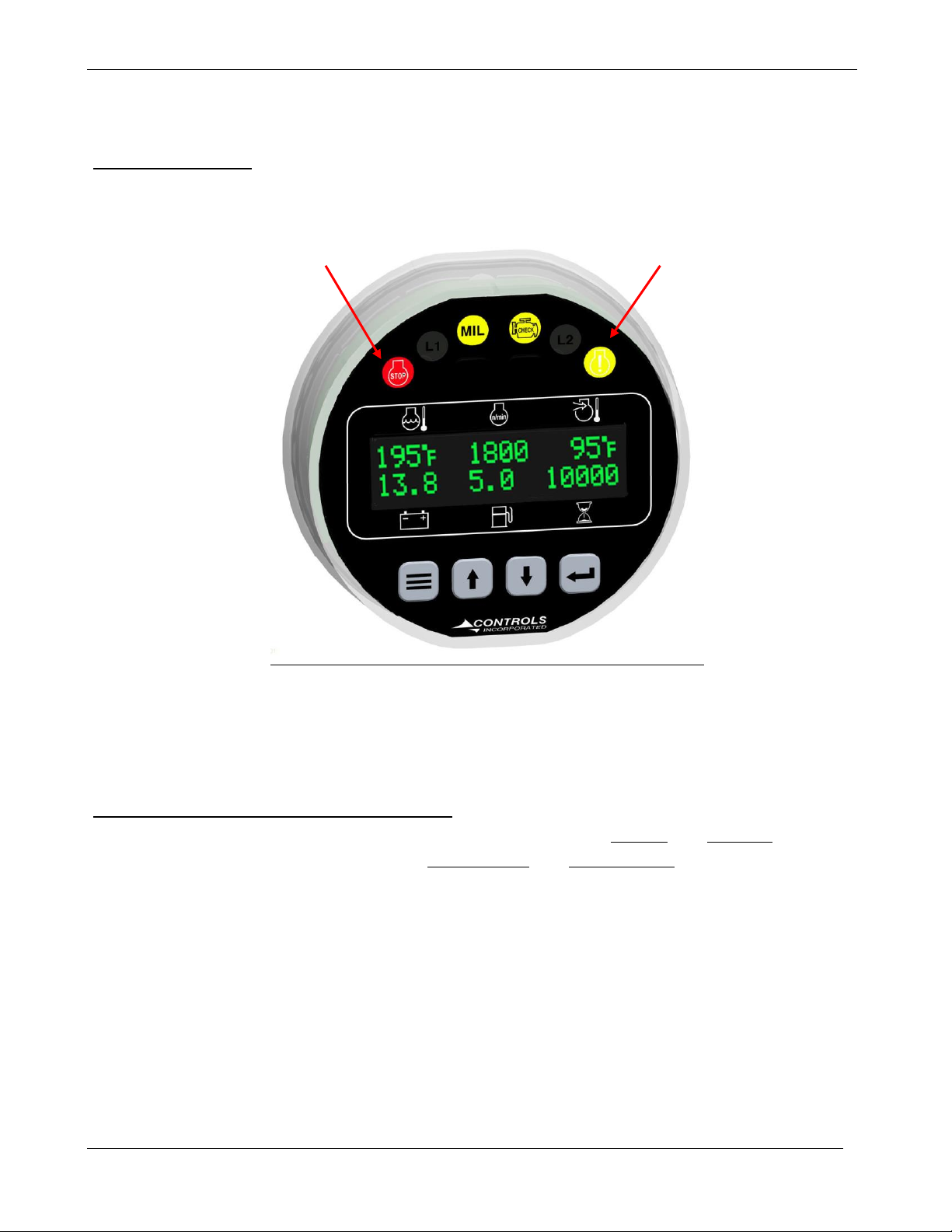
1) Illuminate the appropriate LED indicator lamp
a. Yellow Lamp = Alarm
b. Red Lamp = Engine Shut Down
2) Displays the trouble code (standard SPN.FMI code)
3) Displays a code description on the LCD screen
4) Displays the occurrence count of the code

CONTROLS, INCORPORATED
C O N T R O L S Y S T E M S & S O L U T I O N S
- 9 -
Indicator Lamps
.
Active and Stored Engine ECU Codes
The panel also provides the ability to check the engine ECU for all ACTIVE and STORED engine ECU
codes. These codes can be viewed via the Active Codes and Stored Codes menus.
Engine
Fault
Lamp
Engine
Alarm
Lamp

CONTROLS, INCORPORATED
C O N T R O L S Y S T E M S & S O L U T I O N S
- 10 -
ENGINE PARAMETERS
CAN Bus Communication
This module communicates to the engine ECU via the J1939 CAN Bus network. This is a two wire
connection to the engine ECU. Engine information and alarm codes are broadcast over the CAN bus
from the engine ECU to the controller display. And, the controller communicates throttle
commands to the engine ECU over the CAN bus.
Engine Parameter Viewing
The module has an Engine Parameters viewing menu where the operator may observe the current
conditions of the engine as reported by the engine ECU. The available parameters are listed below
and can be found in the viewing menus.
Engine Parameters
Total Hours
Requested TSC
Load at RPM
Engine Torque
Coolant Temp
Fuel Rate
Manifold Temperature
Potential Voltage

CONTROLS, INCORPORATED
C O N T R O L S Y S T E M S & S O L U T I O N S
- 11 -
CONTROL PANEL DIGITAL INPUTS
The panel has three digital inputs with one available to monitor other components, senders or
signals. This input can be used for a number of purposes including alarms and shut downs.
Input
Heading
Default
Options
Connector
Pin
Digital A4
Normally
Open
Open / Closed
A
4
Action
None
See Note 1
Message
None
See Note 1
Check
Always
Off / Always / Run
Digital B2
Action
Throttle Up
None
B
2
Digital B5
Action
Throttle Down
None
B
5
Note 1:
Message options available for Digital A4:
Action options available for Digital A4:
1) Alarm –Engine shutdown when active with display message as assigned. A red lamp will also
be illuminated.
2) Pre Alarm –Warning message will be displayed along with a yellow lamp when active.
3) Soft Alarm –Recoverable Alarm. Engine will shut down as soon as this input is tripped, but
will recover to running if the condition is cleared quickly enough.
4) None –Set to “None” when no functionality is required.
1) None
12) Low Pump Oil
2) Custom
13) Low Fuel Level
3) Low Water
14) Override Active
4) Low Oil
15) Polish Filter
5)Low Engine Oil
16) Low Hydraulic Fluid
6) Hi Temperature
17) Vacuum High
7) Low Pressure
18) High Hydraulic Temperature
8) External Shutdown
19) Inlet Pressure Loss
9) E-Stop
20) Pipe Pressure Alarm
10) Remote E-Stop
21) Low Coolant Level
11) High Pump Temp
22) Air Filter

CONTROLS, INCORPORATED
C O N T R O L S Y S T E M S & S O L U T I O N S
- 12 -
Digital Input Function Activation
1) Off / Always / Run –Describes when the parameter will be monitored for alarm conditions.
Run refers to when the engine is running. Off disables the alarm conditions. Always enables
the alarm constantly regardless of engine state.
2) Alarm Delay –The time period, after Sender Check Bypass, that the parameter must be on the
alarm condition before the alarm becomes latched.
Note: Activation of the digital function requires a ground signal to Connector A, Pin-4.
Digital B Port Options
1) B2 –Used to attach an external switch for throttle control. Default is Throttle Up
2) B4 –Used to attach an external switch for throttle control. Default is Throttle Down
A Turtle/Hare rocker switch and harness can be purchased separately. This switch
and harness is specifically made to plug into port B of the MVP Module for external
throttle control.
Part Number 70-0402-1

CONTROLS, INCORPORATED
C O N T R O L S Y S T E M S & S O L U T I O N S
- 13 -
Prior to starting the engine, select the proper throttle control mode
and parameters required for application.
Throttle Settings
The following bolded settings are required for manual (and automatic) operation in the Throttle
Configuration menu.
Throttle Configuration
Throttle Type Selection
TSC Minimum Speed
TSC Maximum Speed
TSC Bump Speed
TSC Ramp Rate
Throttle Curve Selection
Multistate Speeds
Manual Throttle Options
1) Multistate Throttle
Multistate throttle provides for one or two specific operating speeds. Pressing the up and down
buttons adjusts engine speed between the selected multistate speed selections.
2) Vernier Throttle
Vernier throttle is standard up and down throttle between the minimum and maximum
selections. The ramp rate is the rate of acceleration in rpm’s per second. The control panel uses
J1939 throttle, also called “torque speed control” or TSC1. This is the most commonly used
throttle option.
3) High/Low
Engine accelerates to the Max speed setting with the UP button is pressed. When the UP button
is released, the engine goes back to idle speed.

CONTROLS, INCORPORATED
C O N T R O L S Y S T E M S & S O L U T I O N S
- 14 -
CONTROL PANEL SPECIFIC ALARMS AND SHUT DOWNS
The panel has its own engine safety alarms and shut downs that can be enabled. These alarms and
shut downs are managed by the control panel independent from the engine ECU. The available
options are listed below and can be accessed via the Engine Safety Configuration menu.
Each alarm must be enabled in the Engine Safety Configuration menu to activate.
Heading
Default
Range
Units
Sender Check Bypass
0:10
0:05 –1:00
Min:Sec
Oil Pressure Check
Run
Off / Always / Run
Oil Pressure Alarm Action
Shutdown
See Note #3
Oil Press Alarm Delay
0:05
0:01 –1:40
Sec
Temperature Check
Run
Off / Always / Run
Low Temp Pre Alarm
0
0 - 240
Deg F
Low Temp Alarm
0
0 - 240
Deg F
High Temp Pre Alarm
220
0 - 240
Deg F
High Temp Alarm
230
0 - 240
Deg F
Coolant Temperature Action
Shutdown
See Note #3
Temp Alarm Delay
0:05
0:01 –1:40
Min:Sec
Intake Temp Check
Run
Off / Always / Run
Low Intake Temp Pre Alarm
0
0 - 240
Deg F
Low Intake Temp Alarm
0
0 - 240
Deg F
High Intake Temp Pre Alarm
180
0 - 240
Deg F
High Intake Temp Alarm
180
0 - 240
Deg F
Intake Alarm Action
Shutdown
See Note #3
Intake Alarm Delay
0:05
0:01 –1:40
Sec
Speed Limit
1600
650-4000
RPM
Torque Derate
50
0 - 100
%
Low Oil Pressure Pre-Alarm
0
0 - 100
PSI
Low Oil Pressure Alarm
1
0 - 100
PSI

CONTROLS, INCORPORATED
C O N T R O L S Y S T E M S & S O L U T I O N S
- 15 -
NOTES:
1) Off / Always / Run –Describes when the parameter will be monitored for alarm conditions. Run
refers to when the engine is running. Off disables the alarm conditions. Always enables the alarm
constantly regardless of engine state.
2) Alarm Delay –The time period, after Sender Check Bypass, that the parameter must be on the
alarm condition before the alarm becomes latched.
3) Alarm Action –The disposition of the engine once the alarm has been activated and the delay
period has expired. Available options are:
A) Shutdown
B) Force to Idle
C) Speed Limit
D) Torque Derate
E) Disabled
Table of contents
Other Controls Laboratory Equipment manuals
Popular Laboratory Equipment manuals by other brands

Thermo Scientific
Thermo Scientific Jewett XR60C Installation and operation manual

Jouan
Jouan SH 105 user manual

Coorstek Sensors
Coorstek Sensors Pegasor AQ Indoor user manual

Scientific Industries
Scientific Industries ROTATOR GENIE SI-2100 operating instructions

NSK
NSK Varios Combi Pro Operation manual

THORLABS
THORLABS OSL2IR user guide