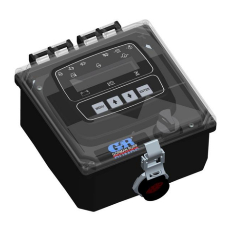
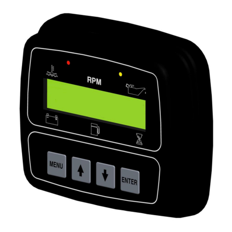
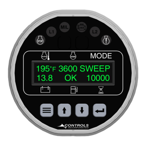
Controls iMech Series User manual

Product Manual
iMech Series
Microprocessor-BasedEngineManagementSystem
ForMechanicalEngines
Part Number: C3M-115
Revision: 1.2
______________________________________________________________________________________________________________________________________
Copyright Controls, Inc.
P.O. Box 368 • Sharon Center, OH 44274
Phone 330.239.4345 • Fax 330.239.2845 • www.controlsinc.com

CONTROLS, INCORPORATED
CON T R O L S Y S T E M S & S O L U T I O N S
- 1 -
1) Introduction
1.1 The C3M-115 is a sealed microprocessor-based engine control system for industrial engines. It is based on
the Controls, Inc.iMech series controller platform with aFreescale 8 bit processor.
1.2 The product is packaged into water tight, polycarbonate enclosureformaximum durability. The controller is
plug & play with a sealed bulkhead engine connector incorporated into thecase.
1.3 The digital OLEDdisplay is 1”H x 4”W with two rows of 16 characters. Character height is approximately ½”.
The display has an operating and storage temp rating of -40C to+80C and isviewable in direct sunlight
1.4 The unit monitorsall critical enginefunctions and hasfull time display of Oil Pressure, Engine Temperature,
Engine Speed, BatteryVoltage, Fuel Level and Engine Hours.
1.5 Analog Input is available forfuel level monitoring.
1.6 Digital Flex Inputis availableforexternal shutdown switches.
1.7 Engine speed control optionsinclude:(requirea thirdparty device to drive)
1.7.1 Off –Nofunctionalityfrom the control panel.
1.7.2 Momentary–Two contactclosures for Upand Down when arrow buttons are pressed.
1.8 The controller with corresponding amber or red LEDilluminations above the digital display monitors engine
safety alarms. Text messages are displayed automatically.
iMech™ C3M-115

CONTROLS, INCORPORATED
CON T R O L S Y S T E M S & S O L U T I O N S
- 2 -
2) Interface
2.1 Display –The backlit digital display is 1”H x 4”W with two rows of 16 characters. Character height is
approximately ½”.
2.2 Display Parameters –The six full-timedisplay parametersare:
∙ Water Temperature ∙ Battery Voltage
∙ Engine RPM ∙ Fuel Level
∙ Oil Pressure ∙ Engine Hours
2.3 Menu & Enter Buttons –To access and scroll menus.
2.4 Up & Down Buttons–For menu navigation andengine speed if configured.
2.5 Amber (Prealarm) LED and Red (Alarm) LED located above the digital display.
2.6 Harness Connector –Ampseal 14 pin.

CONTROLS, INCORPORATED
CON T R O L S Y S T E M S & S O L U T I O N S
- 3 -
3) Enclosure
3.1 Sealed Polycarbonate Enclosure
3.2 O-Ring Seal
3.3 Four 10-32 Brass bosses used to mount unit to sheet metal orvibration isolators.
3.4 Two Hole Requireif mounting directly to sheet metal

CONTROLS, INCORPORATED
CON T R O L S Y S T E M S & S O L U T I O N S
- 4 -
4) Panel Operation
4.1.1 Power Up –Unit performs a power up self-test. Initialization screen displaysfirmware version. LEDs
are illuminated for operation verification.
4.1.2 Preheat Cycle –If programmed, the unit will energizethe preheat circuit. A countdownmessage will
be displayed.

CONTROLS, INCORPORATED
CON T R O L S Y S T E M S & S O L U T I O N S
- 5 -
4.1.3 Acquiring Information –Panel beginsmonitoring sensor inputs. Values are displayed. If no
information isavailable due to a sensor not being connected, the display shows dashed lines.
4.1.4 Typical Operating Screen –After the operator hasstarted the engineusing the key switch,the
panel displays and updates engineinformation continuously. Parameters such as oil pressure and
engine temperature can be configured to be displayed inMetric orEnglish units. Fuel level is
displayedin percentage.

CONTROLS, INCORPORATED
CON T R O L S Y S T E M S & S O L U T I O N S
- 6 -
4.1.5 Engine Warning –When the iMech detects a parameter is outside of its normal operating range, the
amber LED willilluminate and thevalue will flash on the display. These settingsare user
programmable.
4.1.6 Engine Shutdown –When the iMech detects a parameter has exceeded its normal operating range
for a period of time, the red LED will illuminateand a shutdown will occur. A text message will be
displayed on the LCD screen and remain there until the power is cycled. These settings are user
programmable.

CONTROLS, INCORPORATED
CON T R O L S Y S T E M S & S O L U T I O N S
- 7 -
4.1.7 Alarm Logging –Anytimea warning or shutdown condition occurs, the panel will storethe event in
non-volatile memory. The last 16 eventswill be stored with a runningtime stampforreference.
Clearingof the log requires entering the password.
4.1.8 Operation Logging –Anytime the engineis started orstopped, the panel will log the event. The last
16 events will be stored with a running time stamp for reference. Clearing of the log requires entering
the password.

CONTROLS, INCORPORATED
CON T R O L S Y S T E M S & S O L U T I O N S
- 8 -
4.1.9 Throttle Operation –When using the iMech to control engine speed, a third partygovernor or other
actuator devicemust be used.
4.1.9.1 Hi - Lo: LCD Messages of “Throttle Hi” and “Throttle Low” will be used to indicate if the assigned
relay has closed. An open / closed signal will be generated by thepanel. 5-ampmax.
4.1.9.2 Momentary: Directional arrows will be used toindicate when the operator haspressed the Up or
Down arrows buttons. Assigned relayswill close upon activation. 5-amp max.
Up Arrow
Down
Arrow

CONTROLS, INCORPORATED
CON T R O L S Y S T E M S & S O L U T I O N S
- 9 -
5) External Connectors
5.1 C3M-100 Module Connector -The C3M-100 moduleis connected to the internal wiring harness
via a 14-pin TYCO plug. To add additional wires to anyavailable position, please use pins
770854-1. Individual 12” wires with crimped pins are available from CI. P/N 70-0302
Pin
Function
Pin
Function
1
Fuel Solenoid (10 Amp Max)
8
MPU+ or Tach Signal
2
EngineTemp Sender
9
Relay 4Common
3
Battery Positive Common
10
N/A
4
Relay 4N/O
11
Switched Power to C3M
5
Pre Heat Signal (5Amp)
12
Battery Negative
6
N/O of Relay 1** (Ground Signal)
13
Fuel Level Sender
7
Oil Press Sender
14
External Shutdown
** Common tied to batteryminus.
AMPSEAL
776262-1

CONTROLS, INCORPORATED
CON T R O L S Y S T E M S & S O L U T I O N S
- 10 -
6) Controller Menus
6.1 The control panel amenus system toviewvarious enginerelated information and set up the controller
programming. These menus are broken into two sections. They are operator menu andcontroller setup
menu. These menus are accessible via thefour-button pad located on theface of the control panel.
6.2 Operator Menu Ring –Password not required
Operator Menu Categories
Description
Operation Event Log
Viewlast 32 events with runtime stamp
Alarms Event Log
Viewlast 32 alarms withrun timestamp
Module Information
Viewmodel number firmware version
Controller Setup
Gain access to module programming
6.3 Controller Setup Menu Ring –Password required
Controller Setup Categories
Description
Input Configuration
Set up Analog and Digital Options
Output Configuration
Set Relay Assignments
Throttle Configuration
Set Min and Max Speedswith Ramp Rates
Engine Safety Configuration
Set Additional Engine Shutdowns
Module Configuration
Set Display, Units, andSourceoptions
Calibration
Set pulses per revolution
| = Exit Setup
Return to OperatorMenu Categories

CONTROLS, INCORPORATED
CON T R O L S Y S T E M S & S O L U T I O N S
- 11 -
6.4 Menu Access & Navigation
6.4.1 Accessing Menus
1. Press and hold the MENU key & simultaneously press the ENTER key.
6.4.2 Navigation
1. Press MENU to select the next menu category.
2. Press UP to view or edit the specific screen(s) in the category.
3. Press Down to step through logged events.
4. Use the UP and DOWN keys to move among the screens in the category.
5. Press MENU at any time within a category to jump back to the inner ring.
Stepping through menu categories

CONTROLS, INCORPORATED
CON T R O L S Y S T E M S & S O L U T I O N S
- 12 -
Entering into category
Viewing logged events

CONTROLS, INCORPORATED
CON T R O L S Y S T E M S & S O L U T I O N S
- 13 -
6.4.3 Password Entry
The password screen is provided to restrict the edit of sensitive values to authorized personnel.
Not entering a password permits viewing, but no editing of restricted values. Upon encountering
the password screen, a series of dashes will be displayed. To enter the password: [4345].
Entering password
1. Press ENTER to begin editing. The password zeroes will be bracketed.
2. Use the UP and DOWN keys to set the first (leftmost) digit, as you would for a cylinder
combination lock.
3. Press ENTER to freeze that digit and move to the next one on the right.
4. Repeat steps 2 and 3 until all four digits have been set. After the final digit is set, the brackets
automatically disappear.
5. Press the UP key to proceed to the next screens.
If the correct password was entered earlier, navigating back over the password entry screen will
show the password as a row of stars. The password approval state is retained as long as the
panel is powered up.
6.4.4 Editing
Some screens permit parameter changes.
1. Press ENTER to start editing. The value on the screen will be surrounded by brackets. On
password-protected screens, brackets appear only when the correct password was entered
earlier.
2. Use the UP and DOWN keys to adjust the value. In the case of a selection list, the various
possible selections will be shown in a ring. In the case of a variable number, press the
appropriate key to step up/down. For larger changes, press and hold the UP or DOWN key.
(The value will step faster as the key is held down. Stepping will stop when preset value limits
are reached or the key is released.)
3. Press ENTER to save the new value. The brackets will disappear.
4. To skip the edit and retain the old value, press MENU instead of ENTER.
Leaving during editing will abandon the edit, and the old value will be retained.

CONTROLS, INCORPORATED
CON T R O L S Y S T E M S & S O L U T I O N S
- 14 -
6.4.5 Exiting
1. Press and hold the MENU key & simultaneously press the ENTER key.
Exiting the menus
Exiting hasno effect on the password approval. To clear the approved password state,
power cycle the panel.

CONTROLS, INCORPORATED
CON T R O L S Y S T E M S & S O L U T I O N S
- 15 -
7) Input Configuration
Heading
Default
Range
Units
Your Settings
Digital 1 Configuration
Open
N/O or N/C
Digital 1 Action
Alarm
See Note 2
Digital 1 Check
Always
Off/ Always/ Run
Digital 1 Message
Ext Shutdown
Notes
1) Off / Always / Run –Describes when the parameter will be monitored for alarm conditions. Run refers towhen
the engine is running. Off disables the alarm conditions. Always enables the alarm constantly regardless of engine
state.
2) Action –What will occur when the digital inputis considered active.
Alarm –Shutdown the engine byopening thefuel relay. A red lamp andthe message associated with the
input will appear.
Prealarm –A warning will beindicated bythe yellow lampilluminating and amessage will appear
Soft Alarm –Thefuel relay will open aslong as the condition existsand a red lampwill appear with the
message. If eventdoes notlast long enough to shut the engine down, the engine will resume running when the
event is no longer active.
None –No action will be taken.

CONTROLS, INCORPORATED
CON T R O L S Y S T E M S & S O L U T I O N S
- 16 -
8) Output Configuration
Heading
Default
Range
Units
Your Settings
Relay 1Function
Throttle B0
See Relay Notes
Relay 1Polarity
Positive
Positive / Invert
Relay 1Initial State
Off
Off / On
Relay 2Function
Fuel
See Relay Section
Relay 2Polarity
Positive
Positive / Invert
Relay 2Initial State
On
Off / On
Relay 3Function
Preheat
See Relay Section
Relay 3Polarity
Positive
Positive / Invert
Relay 3Initial State
Off
Off / On
Relay 4Function
Throttle B1
See Relay Notes
Relay 4Polarity
Positive
Positive / Invert
Relay 4 Initial State
Off
Off / On
Relay Notes:
A total of four relayscan beassigned for differentuses depending on application. Two 10 amp relaysand two 5
amp relaysareused. Relay2 and Relay 4are 10 amp, while Relays 1 / 3 are 5 amp. All relays use battery plus to
switch with the exception of Relay1 whose common is tied to ground.
1) Relay Functions –A total of four relays can be assignedfor different uses depending on application.
a. None –Assign non when not used
b. Preheat –Relay will be active during programmed preheat period. Used to drive a preheat relay.
c. Fuel / Run –Relay will be active during an engine startrequest and while the engine isrunning.
Used to drive the engine’s ecu circuit. Also active when requesting active and stored J1939 codes.
d. SwitchTrip –Relay will be active if digital input is active.
e. Engine Run –Relay will beactive when engine RPM is greater than 600. Typically used to drive
an auxiliary circuit such as louvers or send a signal to amonitoring station.
f. Alarm –Relay will be active when there isan alarm condition. Typically used to drive analarm
horn orlamp. Also can be used to send a signal to amonitoringstation
g. Prealarm –Relay will be active when there is a prealarm condition. Typically used to drive an
alarm horn or lamp. Also can be used to send a signal to amonitoring station
h. Pre+Alarm Horn –Energizes an external audible alarm when a Prealarm oralarm condition is
present. Pressing the ENTER button will silence.
i. Alarm Horn –Energizes an external audible alarm when an alarm conditionis present. Pressing
the ENTER button will silence.
j. Throttle B1 –Reservedfor OEM applications.
k. Throttle B0 –Reservedfor OEM applications.
l. Custom 1 - Reserved for OEM applications.

CONTROLS, INCORPORATED
CON T R O L S Y S T E M S & S O L U T I O N S
- 17 -
2) Relay Polarity
a. Positive –Relay acts as a normally open contact.
b. Invert –Relay acts as a normally closed contact.
3) Relay Initialized State
a. On –Relay is activated upon power up.
b. Off- Relay is not activatedupon power up.
9) Throttle Configuration
Heading
Default
Range
Units
Your Settings
Throttle Type
Momentary
See Throttle Notes
Throttle Notes:
Multiplethrottletypescan be selected for operatingin manual run mode. These include thefollowing.
1) Throttle Types
a. Momentary –Individual Up and down relayswill close when the Up and Down arrowkeysare
pressed.

CONTROLS, INCORPORATED
CON T R O L S Y S T E M S & S O L U T I O N S
- 18 -
10) Engine Safety Configuration
Heading
Default
Range
Units
Your Settings
Press and Temp Units
English
English / Metric
Sender Check Bypass
0:10
0:05 –1:00
Min:Sec
Fuel Level Sender
S-W
S-W / VDO
Fuel Level Check
Off
Off / Always / Run
LowFuel Prealarm
20
0 - 100
%
LowFuel Alarm
1
0 - 100
%
Fuel Alarm Delay
0:01
0:01 –1:40
Sec
Oil Pressure Sender
S-W
S-W / VDO
Oil Pressure Check
Run
Off/ Always/ Run
LowOil Press Prealarm
15
0 - 100
PSI
LowOil Press alarm
10
0 - 100
PSI
Oil Press Alarm Delay
5
0:01 –1:40
Sec
TemperatureSender
S-W
S-W / VDO
Temperature Check
Run
Off/ Always/ Run
LowTemp Prealarm
0
0 - 300
Deg F
LowTemp Alarm
0
0 - 300
Deg F
High Temp Prealarm
220
150 - 300
Deg F
High Temp Alarm
230
150 - 300
Deg F
Temp Alarm Delay
0:05
0:01 –1:40
Min:Sec
Battery Volts Check
Off
Off/ Always/ Run
Lo Battery Prealarm
10.0
0.0 –40.0
Volts
Hi Battery Prealarm
15.0
0.0 –40.0
Volts
Battery V Trim
5
0-10
100mV
Over Speed Check
Run
Off/ Always/ Run
Over Speed Alarm
4200
650 - 5000
RPM
Over Speed Alarm Delay
0:05
0:01 –1:40
Min:Sec
Notes
1) Off / Always / Run –Describes when the parameter will be monitored for alarm conditions. Run refers towhen
the engine is running. Off disables the alarm conditions. Always enables the alarm constantly regardless of engine
state.
2) Alarm Delay –The time period, after Sender Check Bypass, thatthe parameter must beon the alarm condition
before the alarm becomes latched.

CONTROLS, INCORPORATED
CON T R O L S Y S T E M S & S O L U T I O N S
- 19 -
11) Module Configuration
Heading
Default
Range
Units
Your Settings
Preheat
0:10
0:00-2:00
Min:Sec
Hour Meter
0
Hours
Clear Operation Log
No
Yes / No
Clear Alarm Log
No
Yes / No
LCD Auto Contrast
On
On /Off
LCD Contrast
55
0 -100
%
LCD Backlight
100
0 - 100
%
VFDIntensity
100%
25/50/75/100
%
12) Calibration
Heading
Default
Range
Units
Your Settings
Flywheel Teeth
10
1-200
Auto Set Teeth
No
Yes / No
Other manuals for iMech Series
1
This manual suits for next models
1
Table of contents
Other Controls Laboratory Equipment manuals
Popular Laboratory Equipment manuals by other brands

MRC
MRC MIXP Series Operation manual

Bibby Sterilin
Bibby Sterilin stuart SM5 Instructions for use

Harvard Apparatus
Harvard Apparatus Panlab LE12404 Hardware user manual

WDT
WDT DUFTDOS-0-Compact operating instructions

MSE
MSE MicroCentaur Plus user manual

DDS Calorimeters
DDS Calorimeters CAL3K 3K-F installation guide