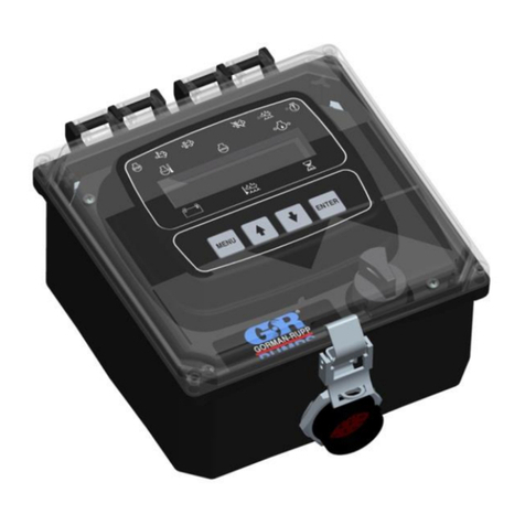
Controls WIZARD 2 50-C92AXX User manual

MANUALE DI ISTRUZIONI
INSTRUCTION MANUAL
50-C92AXX, 50-C13A0X
50-C23A0X, 50-C34A0X
Compression and flexural testers


Manuale di Istruzioni
Instruction Manual
Rev.1 EN 23/08/2018
1
Index
1.
INTRODUCTION 4
1.1 Icons appearing in the manual .............................................................................................9
1.2 Manual revision history .....................................................................................................10
1.3 Symbols used.....................................................................................................................11
1.4 Intended use and improper use ..........................................................................................12
1.5 Safety information .............................................................................................................13
1.6 Environmental risks and disposal ......................................................................................22
1.7 CE declaration ...................................................................................................................23
2.
DESCRIPTION 24
2.1 Frames ...............................................................................................................................27
2.2 Compression platens..........................................................................................................27
2.3 Hydraulic power unit .........................................................................................................27
2.4 WIZARD 2 display unit.....................................................................................................27
2.5 Connections .......................................................................................................................28
2.6 Identification plate.............................................................................................................29
2.7 Commands and controls ....................................................................................................30
2.7.1
Flow control valve ......................................................................................................... 31
2.8 Technical specifications.....................................................................................................32
3.
INSTALLATION 38
3.1 Shipment............................................................................................................................39
3.2 Unpacking and inspection..................................................................................................42
3.2.1
How to remove the equipment from the shipping crate ................................................. 43
3.3 Positioning of the unit and space requirements .................................................................45
3.4 Mounting the control unit ..................................................................................................47
3.5 Positioning of the display ..................................................................................................48
3.6 Electrical requirements ......................................................................................................49
3.7 Electrical connections........................................................................................................50
3.8 Hydraulic connections .......................................................................................................52
3.9 Installation of the printer paper..........................................................................................55
4.
USE OF THE EQUIPMENT 56
4.1 Switching on the equipment ..............................................................................................57
4.2 MAIN MENU....................................................................................................................58
4.2.1
TEST RUN menu........................................................................................................... 59
4.2.2
ARCHIVE menu............................................................................................................ 65
4.2.3
OPTIONS menu............................................................................................................. 66
4.2.3.1
CLOCK option............................................................................................................... 66

Manuale di Istruzione
Instruction Manual
23/08/2018 Rev.1 EN
2
4.2.3.2
UNIT OF MEASURE option ......................................................................................... 67
4.2.3.3
DELETE ARCHIVE option........................................................................................... 67
4.2.3.4
RESULTS option ........................................................................................................... 68
4.2.3.5
LANGUAGE option ...................................................................................................... 68
4.2.4
CALIBRATION menu................................................................................................... 69
4.3 Carry out a test .................................................................................................................. 70
4.3.1
Selection of the frame to use for 50-C92A2X machine.................................................. 72
4.3.2
Use of the load control valve.......................................................................................... 73
4.3.3
Testing a sample............................................................................................................. 74
4.4 Stopping the cycle via the Emergency button................................................................... 79
4.5 Switching off the unit........................................................................................................ 81
5.
MAINTENANCE 82
5.1 Operator’s preventive maintenance .................................................................................. 84
5.1.1
Checking the status of the safety devices .......................................................................85
5.1.2
Checking the oil level in the tank ...................................................................................88
5.2 Authorized service engineer maintenance actions ............................................................ 89
5.2.1
Checking the centering of the ram assembly.................................................................. 90
5.2.2
Checking the hydraulic circuit........................................................................................ 92
5.2.3
Checking the status of distance pieces ........................................................................... 94
5.2.4
Performing the maintenance of the spherical seat .......................................................... 95
5.2.5
Checking the calibration of the channels........................................................................ 96
5.2.5.1
Calibration verification................................................................................................... 98
5.2.5.2
Calibration.................................................................................................................... 102
5.2.6
Replacing the oil of the hydraulic circuit ..................................................................... 107
6.
DIAGNOSTICS TROUBLESHOOTING 109
6.1 System (Hidden) menu.................................................................................................... 110
6.1.1
CHANNELS SET-UP option....................................................................................... 112
6.1.1.1
ACTIVE CHANNEL option ........................................................................................ 112
6.1.1.2
FULL SCALE and PRELOAD settings ....................................................................... 113
6.1.2
SERIAL NUMBER option........................................................................................... 114
6.1.3
MEMORY RESET option............................................................................................ 115

Manuale di Istruzioni
Instruction Manual
Rev.1 EN 23/08/2018
3
This instruction manual is an integral part of the machine and should be read before using the machine and be
safely kept for future reference.
CONTROLS reserves all rights of this manual, no part or whole can be copied without the written permission of
CONTROLS.
The proper use of this machine must be strictly adhered to, any other use must be considered as incorrect.
The manufacturer cannot be held responsible for damage caused by incorrect use of the machine.
The machine must not be tampered with for any reason. In case of tampering, the manufacturer declines any
responsibility of functioning and safety of the machine.
This Manual is published by CONTROLS.
CONTROLS reserves the right to update its manuals without notification in order to correct possible typing
errors, mistakes, updating of information and/or updating of programs and/or accessories.
Such changes will be inserted in the latest edition of the current manual
.
The present in English is the original version of the manual. Printed in Italy

Manuale di Istruzione
Instruction Manual
23/08/2018 Rev.1 EN
4
1. INTRODUCTION
NOTE:
The present manual is updated for the product it is sold with in order to grant an adequate
reference in operating and maintaining the equipment.
The manual may not reflect changes to the product not impacting service operations.
50-C92AXX
These Multipurpose compression / flexure testers have been designed for various
applications in which a limited maximum load is requested, together with a large testing
space. They are suitable to determinate compressive strength on lightweight concrete,
soil-cement specimen, high strength cement and refractory.
The large testing space is ideal for performing, with the suitable accessory, splitting tests
and flexural tests on concrete specimens. The pedestal is not included and has to be
ordered separately (code: 50-C99/B).
They are available in the two different versions:
Single compression station, 500 kN or 600 kN cap.:
for compression tests on low strength specimens. The Class 1 accuracy can be extended
from 1% of testing machine full scale with special calibration procedures.
Double station model, 600/15 kN cap.:
extends the possible applications to flexural tests on cement and com pression tests on
low strength specimens. The Class 1 accuracy can be extended with special calibration
procedures (see Technical Specifications).
Frames and compression platens
High rigidity solid one piece steel frame. Spherical seat allows free alignment at the
initial contact with the specimen. For compression platens see Technical. Pedestal (code:
50-C99/B) not included.
WIZARD 2 Semi-Automatic Power and Control system
Dual stage pump: low pressure/high delivery for fast piston approach and high
pressure/low volume for loading. Fitted with special hand operated pressure-compensated
proportional valve for the manual preset of load rate.
Load measurement: set up of specimen dimensions; easy preload zeroing; real time
display of load and stress; real time display of applied load rate by symbols for easy
adjustment; digital calibration; effective resolution 1/65000; LAN port for PC connection.
The WIZARD 2 can be factory fitted with an internal serial printer.
Safety features
Includes: pressure valve to avoid machine overloading; piston travel limit switch;
emergency stop button; front door and rear transparent guard.

Manuale di Istruzioni
Instruction Manual
Rev.1 EN 23/08/2018
5
The automatic test procedure, once the specimen has been positioned and centered and
the machine switched on is:
•Set test parameters, including load rate, on the touch screen (can be avoided by
default for repetitive tests);
•Press the start button on the touch screen;
•Move the oil delivery valve upwards;
•The machine automatically starts the rapid platen approach, switches to the test
speed once the specimen comes into contact with the upper platen and, finally,
releases the pressure upon specimen failure;
•Save the test including data results and load/time graph. The test execution
conforming to standards can be easily proved;
•Move the oil delivery valve downwards.
Main features are:
•Multipurpose machine ideal for Central laboratories, for testing Cement, Mortars,
Resins, Refractory, Lightweight concrete, Soil-cement specimens etc;
•digital control system with wide high-contrast display 4x20 characters and 6 keys
membrane keyboard;
•real time display of load and stress and applied load rate by symbols for easy
adjustment;
•accuracy Class 1 (EN) and Class A (ASTM) starting from 10% of full scale;
•special calibration starting from few kilonewtons available on request;
•optional control of a second frame for single chambers testers. Active frame selection
via manual lever;
•optional internal graphic printer;
•universal compression testers, in practice, suitable to house various accessories for
testing cement, mortar, resins and other materials;
•LAN port for PC connection and data transmission during test execution;
•Data storage on removable USB pen drive.

Manuale di Istruzione
Instruction Manual
23/08/2018 Rev.1 EN
6
Here is the list of models available and their relevant main specifications:
Single testing chamber models
50-C92A02
600 kN cap., WIZARD 2 Semi-automatic COMPACT-Line compression tester, load
measurement with pressure transducer. 230 V, 50-60 Hz, 1ph
50-C92A03
Same as above but 220V, 60 Hz, 1ph
50-C92A04
Same as above but 110V, 60 Hz, 1ph
50-C92A12
500 kN cap., WIZARD 2 Semi-automatic COMPACT-Line compression tester, load
measurement with load cell. 230 V, 50-60 Hz, 1 ph
50-C92A13
Same as above but 220V, 60 Hz, 1ph
50-C92A14
Same as above but 110V, 60 Hz, 1ph
Double testing chambers models
50-C92A22
15/600 kN cap., WIZARD 2 Semi-automatic COMPACT-Line Double Station
compression tester, load measurement of the 15 kN station with high precision load cell
and 600 kN station with pressure transducer. 230 V,50-60 Hz, 1 ph
50-C92A23
Same as above but 220V, 60 Hz, 1ph
50-C92A24
Same as above but 110V, 60 Hz, 1ph
The machine must be completed with suitable distance pieces conforming to the
specimen size.

Manuale di Istruzioni
Instruction Manual
Rev.1 EN 23/08/2018
7
50-C13A0X/C23A0X/C34A0X
Frame
Rigid welded steel construction. Spherical seat allows free alignment at the initial contact
with the specimen.
Compression platens
See table. Traceable certificate of surface hardness available on request.
Wizard, Semi-Automatic power and control system
Dual stage pump: low pressure/high delivery for fast piston approach and high
pressure/low volume for loading. Special hand operated pressure-compensated
proportional valve for the manual preset of load rate requiring just occasional operator’s
intervention.
Hardware
2 analogue channels, 4 x 20 characters alphanumeric display, 65˙000 points high
resolution/stability analogue channels, sampling rate 50/sec, large storage capacity for
test data on USB memory stick, ethernet port to download data to PC using the SW/TRM
software.
Firmware
Simultaneous display of load, specific load and actual load rate, LAN connection to PC
for data transmission in real time, easy firmware update through Ethernet port, memory
management with options to display tests stored on USB memory stick, download data to
internal printer or PC, delete single tests or reset the entire memory, Multi-coefficient
calibration procedure with automatic storage of data without manual editing (using a
suitable load cell and readout unit), language and units selection (kN, ton, lbf).
Safety features
Includes: Max. pressure valve to avoid machine overloading; piston travel limit switch;
emergency stop button; front and rear flexible transparent fragment guard.
Main features are:
•Rigid welded steel construction
•Accuracy Class 1 (EN) starting from 10% of full scale (from 1% on request)
•2 channels for load sensors with 65000 div. resolution (better than 0.01% of full scale)
•Unlimited store capacity on USB pen drive of test data downloadable to PC via LAN
port
•Digital readout unit with wide high-contrast display 4 x 20 characters and 6 keys
membrane keyboard
•Real time display of load/stress and applied load rate by symbols for easy adjustment
•Dual stage pump: low pressure/high delivery for fast piston approach and high
pressure/low volume for loading
•Special hand operated pressure-compensated proportional valve for the manual preset
of load rate requiring just occasional operator’s intervention
•Optional control of a second frame
•Optional internal printer

Manuale di Istruzione
Instruction Manual
23/08/2018 Rev.1 EN
8
Here is the list of models available and their relevant main specifications:
50-C13A02
WIZARD 2, Semi- Automatic Compact-Line Gen. Util. compression tester, 1500 kN
cap., for cubes up to 150 mm and cylinders up to dia. 160 x 320 mm. 230 V, 50 Hz, 1 ph.
50-C13A03
Same as above but 220 V, 60 Hz, 1 ph.
50-C13A04
Same as above but 110 V, 60 Hz, 1 ph.
50-C23A02
WIZARD 2, Semi- Automatic Compact-Line Gen. Util. compression tester, 2000 kN
cap., for cubes up to 150 mm and cylinders up to dia. 160 x 320 mm. 230 V, 50 Hz, 1 ph.
50-C23A03
Same as above but 220 V, 60 Hz, 1 ph.
50-C23A04
Same as above but 110 V, 60 Hz, 1 ph.
50-C34A02
WIZARD 2, Semi-Automatic Compact-Line Gen. Util. compression tester, 3000 kN cap.,
for cubes up to 200 mm and cylinders up to dia. 160 x 320 mm. 230 V, 50 Hz, 1 ph.
50-C34A03
Same as above but 220 V, 60 Hz, 1 ph.
50-C34A04
Same as above but 110 V, 60 Hz, 1 ph.
The machine must be completed with suitable distance pieces conforming to the
specimen size.
The device must be used in compliance with the procedures described in this manual.
Never use the device for purposes different from those herewith indicated.
This manual is applicable for units having firmware release equal to/higher than 1.05.
Fig. 1-1
Please read this manual thoroughly before you start using the equipment.

Manuale di Istruzioni
Instruction Manual
Rev.1 EN 23/08/2018
9
1.1 Icons appearing in the manual
This icon indicates a NOTE; please read thoroughly the items marked by this picture.
This icon indicates a WARNING message; the items marked by this icon refer to the
safety aspects of the operator and/or of the service engineer.

Manuale di Istruzione
Instruction Manual
23/08/2018 Rev.1 EN
10
1.2 Manual revision history
Revision/Date Change description
Rev. 1
August 23
rd
201
8
Manual release

Manuale di Istruzioni
Instruction Manual
Rev.1 EN 23/08/2018
11
1.3 Symbols used
In this manual and on the equipment itself, apart from the symbols indicated on the
control panel, the following icons are also used:
Symbol Description
Mains switch:
O = device not connected to the mains line
I = device connected to the mains line
Emergency stop switch
Dangerous voltage
Hand injury
Conformity to the CE Directive

Manuale di Istruzione
Instruction Manual
23/08/2018 Rev.1 EN
12
1.4 Intended use and improper use
The 50-C92AXX WIZARD 2 Multipurpose Compression and Flexural testers can only
be used to perform building material tests according to the relevant international
standards.
The unit is designed to be operated by one operator that has to install the necessary
distance pieces, load-unload the sample from the frame, input the test parameters and start
the test.
During normal operation, the working area of the equipment is the front side where the
operator’s controls and the display are located.
The operator is responsible of starting-up the equipment, performing the test sequence,
shutting down the equipment and eventually stopping it in case any emergency conditions
are met.
The operator must be trained on the correct use of the machine and the relative safety
aspects of its use.
The machine should be used following the procedures described in this manual.
Never use the machine for reasons other than those for which it was designed and
manufactured. Any other use of the machine is to be considered improper, not foreseen
and hence dangerous.
CONTROLS will not be responsible for improper use of the machine.

Manuale di Istruzioni
Instruction Manual
Rev.1 EN 23/08/2018
13
1.5 Safety information
WARNING:
Please read this chapter thoroughly.
CONTROLS designs and builds its devices complying with the related safety
requirements; furthermore it supplies all information necessary for correct use and the
warnings related to use of the equipment.
CONTROLS will not to be held responsible for:
•use of the equipment different than the intended use;
•damages to the unit, to the operator, caused both by installation and maintenance
procedures different than those described in this manual supplied with the unit, and
by wrong operations;
•mechanical and/or electrical modifications performed during and after the
installation, different than those described in this manual.
The unit is not designed to be used in an explosive atmosphere.
Installation and any technical intervention must only be performed by qualified
technicians authorized by CONTROLS.
Only authorised personnel can remove the covers and/or have access to the components
under voltage.
During normal use, if the operator detects irregularities or damages, he/she should
immediately inform the authorized technical personnel.
Maintenance and service activities can only be performed by skilled authorized technical
personnel that have been properly trained on the residual risks of the equipment.
It is responsibility of the purchaser to make sure that the operators have been properly
instructed concerning the safety issues and the residual risks related to the equipment.

Manuale di Istruzione
Instruction Manual
23/08/2018 Rev.1 EN
14
The machine is equipped with the following devices to limit the residual risks in using it:
•Emergency button that switches OFF the unit once pressed, thus stopping the raising
of the piston;
•Max. pressure valve to avoid machine overloading;
Fig. 1-2
Emergency button
Max. pressure valve

Manuale di Istruzioni
Instruction Manual
Rev.1 EN 23/08/2018
15
•Ram travel switch to prevent the excessive piston travel; when triggered it disables
the functioning of the pump motor;
Fig. 1-3
•Front door and rear transparent fragment guard;
Fig. 1-4
Limit switch
Front fragment guard

Manuale di Istruzione
Instruction Manual
23/08/2018 Rev.1 EN
16
•On the motor connection box, input for ram travel microswitches to prevent the
excessive piston travel; when triggered it disables the functioning of the pump motor;
Fig. 1-5
•Access panels to internal parts locked with screws.
Connector for overtravel microswitch

Manuale di Istruzioni
Instruction Manual
Rev.1 EN 23/08/2018
17
The following table lists those parts of the equipment that may present some residual
risks for the safety of the personnel if the instructions provided in this manual are not
duly followed.
Personnel Area with residual risks
Operator The sample during load-unloading phase from the frame, due to its weight
and sharp surfaces. Use suitable personal protection devices (e.g. gloves,
protective shoes, etc.).
The distance pieces and platens during the installation phase on the frame,
due to their weight. Use suitable personal protection devices (e.g. gloves,
protective shoes, etc.).
The area around the frame during the execution of the test, in case of test on
explosive samples and with the front and rear fragment guards not in place.
The gap between the sample and the upper platen on the frame during the
compression phase, although the maximum speed is very low (max. 40
mm/min).
Technical personnel
Above listed areas
Area around the hydraulic tubes, due to the high pressure of the oil, in case
the tubes are damaged or not properly attached
Areas a
round compartments closed by removable panels
Areas around compartments that contain electrical parts
For continued fire protection, replace fuses with same type and rating. Also,
in case of failure, components may only be replaced by using original spare
parts. It is in the responsibility of the purchaser to insure that fire prevention
policies are properly implemented according to the CE provisions.
Personnel
responsible of
transportation and
moving of the
equipment
Raising and moving of the equipment from the wooden crate must be
performed by people properly trained and equipped with suitable personal
protection devices (e.g. gloves, helmet, etc.). Failure to follow the
instructions above may endanger the personnel involved.

Manuale di Istruzione
Instruction Manual
23/08/2018 Rev.1 EN
18
Here follows a list of all WARNINGs present in the manual; please see relevant chapters
for full details on each related safety issue.
WARNING:
Do not use the USB port to re-charge batteries of external devices (e.g mobile phone,
audio-video players, etc.). It is also mandatory to connect/disconnect the USB memory
stick with the unit OFF.
CONTROLS will not be held responsible for damages to persons and/or properties in
case these instructions are not strictly followed.
WARNING:
When operating with the covers open/removed and the unit is attached to the mains line,
care must be taken as high voltage is present in some parts of the unit (e.g. electrical
panel). Only authorized and qualified service technicians are allowed to open /remove
covers.
WARNING:
All safety devices must be functional at all times. Damaged protective covers or devices
must be replaced immediately. When safety components are replaced, the protective
devices are to be properly attached and tested. Any manipulation of the safety devices
endangers the operating personnel.
WARNING:
To avoid direct contact with the oil of the hydraulic circuit, always wear protective gloves
while performing the checking.
WARNING:
Raising and moving of the equipment must be performed by people properly trained and
equipped with suitable personal protection devices (e.g. gloves, helmet, etc.). Failure to
follow the instructions above may endanger the personnel involved.
WARNING:
The wooden crate is high; be careful in balancing while raising it.
WARNING:
If the instructions to remove the equipment from the shipping box are not carefully
followed, damages to the equipment cabinet may result. This will void the warranty terms
of the equipment.
WARNING:
Do not stand under suspended loads
This manual suits for next models
3
Table of contents
Other Controls Laboratory Equipment manuals
Popular Laboratory Equipment manuals by other brands

Thermo Scientific
Thermo Scientific Jewett XR60C Installation and operation manual

Jouan
Jouan SH 105 user manual

Coorstek Sensors
Coorstek Sensors Pegasor AQ Indoor user manual

Scientific Industries
Scientific Industries ROTATOR GENIE SI-2100 operating instructions

NSK
NSK Varios Combi Pro Operation manual

THORLABS
THORLABS OSL2IR user guide