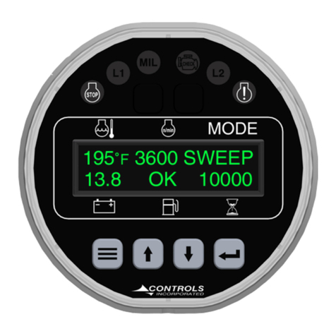
Controls 29284-083 User manual

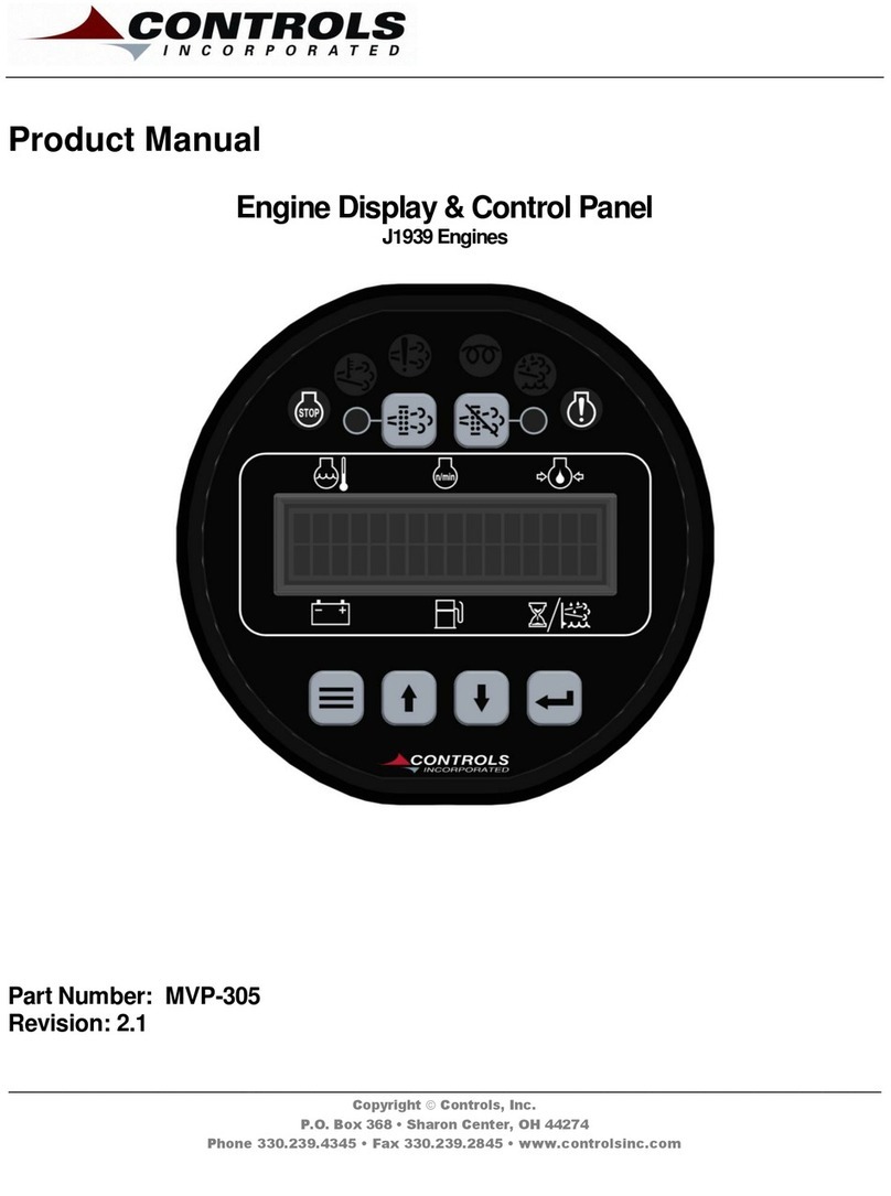
Product Manual
Part Number: 29284-083
Revision: 2.0
______________________________________________________________________________________________________________________________________
Copyright Controls, Inc.
P.O. Box 368 • Sharon Center, OH 44274
Phone 330.239.4345 • Fax 330.239.2845 • www.controlsinc.com

CONTROLS, INCORPORATED
C O N T R O L S Y S T E M S & S O L U T I O N S
- 1 -
TABLE OF CONTENTS
QUICK SET UP……………..………………………………………….…………………..……………………………….……………….…………...2
PRIOR TO STARTING ENGINE………………..……………………………………………………………….……………….…………...3
ENGINE TYPE: MECHANICAL VS. J1939 ENGINE
MANUAL OPERATION THROTTLE SETTINGS
STARTING THE ENGINE………………………………..………………………….………………………………………….………..…….....5
MANUAL START/STOP
PANEL CONNECTORS…………………………………...……………………………………………………………….………………………6
ENGINE HARNESS CONNECTOR
TRANSITION HARNESS FOR MECHANICAL ENGINES…….....……………...……………………………………….…7
MODULE CONNECTORS……………………………………………………………………………………………….…….……………….…8
ENGINE ALARMS, CODES AND MESSAGES…………………………………………………………………………….........10
ENGINE ECU ALARMS/DE-RATE/SHUT DOWNS
PANEL ALARM ANNUNCIATION AND CODE READER
PANEL INDICATION LAMPS
ACTIVE AND STORED ENGINE ECU CODES
CONTROL PANEL SPECIFIC ALARMS AND SHUT DOWNS………………………………………….……………12
CONTROL PANEL SPECIFIC SAFETY ALARMS
CONTROL PANEL ANALOG AND DIGITAL INPUTS………………………………………………………………………13
ANALOG INPUTS
DIGITAL INPUTS
CONTROL PANEL RELAY OUTPUTS…………………………………………………………………..……………………….....…15
MENU SYSTEM……………………………………………………………………………………………..…………………………………….……16
MENU ACCESS, EXIT AND NAVIGATION
MENUS SYSTEM STRUCTURE (VIEWING & CONFIGURATION MENUS)
VIEW MENUS
CONFIGURATION MENUS
COMMUNICATIONS……………………………………………………………………………………..…………………………………….……23
CAN BUS
BATTERY BACKUP……………………………………………………………………………………..…………………………………….……24
EMISSIONS MONITORING…………………………………………………………………………………………………….……………....25
EMISSIONS INFORMATION
REGENERATION
STANDARD REGENERATION
SERVICE LEVEL REGENERATION
REGEN INHIBIT

CONTROLS, INCORPORATED
C O N T R O L S Y S T E M S & S O L U T I O N S
- 2 -
QUICK SETUP
A Quick Setup menu is available for initial panel installation.
Quick Setup
Engine Type
Mechanical or Electronic J1939
Mechanical
Flywheel Teeth
# flywheel teeth or alternator tach
Preheat Time
Preheat time in seconds
Performance Display
Turn “On” to enable the performance display
Electronic J1939
Engine Manufacturer
Select engine manufacturer
TSC Minimum Speed
Minimum engine speed
(engine not allowed to go below this value)
TSC Maximum Speed
Maximum engine speed
(engine not allowed to go above this value)
Performance Display
Turn “On” to enable the performance display
Actuator Throttle Kit
An actuator throttle kit is available for mechanically governed engines to provide throttle control
through the control panel.

CONTROLS, INCORPORATED
C O N T R O L S Y S T E M S & S O L U T I O N S
- 3 -
PRIOR TO STARTING THE ENGINE
Prior to starting the engine, the following operational settings are required.
Engine Type Setting
The paneloperates with both mechanical and J1939 engines. A menu selection is provided in the
Parameter Configuration menu to match the panel to the engine. For mechanical engines, select
“mechanical”. For J1939 engines, select “electronic”.
Manual Operation Throttle Settings
The bolded settings are required in the Throttle Configuration menu list below.
Throttle Configuration
Throttle Type - (Default = Off)
TSC Mode Selection
TSC Min Speed Selection (Default = 800 rpm)
TSC Max Speed Selection (Default = 2400 rpm)
TSC Bump Speed Selection (Default = 20 rpm)
TSC Ramp Rate Selection (Default = 100 rpm/sec)
Throttle Curve Selection
Multistate Speed 1 Selection
Multistate Speed 2 Selection
Multistate Speed 3 Selection
Multistate Speed 4 Selection
Manual Throttle Options
1) Vernier Throttle (Default)
Vernier throttle is standard up and down throttle between the minimum and maximum
selections. The ramp rate is the rate of acceleration in rpm’s per second. The control panel
uses J1939 throttle, also called “torque speed control” or TSC1.
2) Multistate Throttle
Multistate throttle provides for one, two, three orfour specific operatingspeeds. Pressing the up
and down buttons adjusts engine speed between the selected multistate speed selections.
Multistate Speeds –Programmed speed settings must be in an increasing order. For
example, Speed 1 = 1000, Speed 2 = 1400, Speed 3 = 1500.

CONTROLS, INCORPORATED
C O N T R O L S Y S T E M S & S O L U T I O N S
- 4 -
STARTING THE ENGINE
The control panel operates in manual throttle mode when the engine is started manually and
operates in automatic throttle mode with the key in the “Auto” position.
MANUAL START/STOP OPERATION
1) Engine Start/Stop –Turn key to run position manually
2) Engine Throttle –Push up and down buttons
Up Arrow
Increase
Speed
Decrease
Speed

CONTROLS, INCORPORATED
C O N T R O L S Y S T E M S & S O L U T I O N S
- 5 -
PANEL CONNECTORS
Pin
Description
A
OPEN
B
Battery Positive
C
MPU-
D
Crank Signal
E
Battery Negative
F
CAN Shield
G
Fuel Solenoid/ECU Signal
H
Temperature Sender Input
J
Alternator Excite
K
Speed Signal/MPU+
L
Pre-Heat Signal
M
OPEN
N
Fuel Level Sender Return
P
Fuel Level Sender Input
R
OPEN
S
OPEN
T
OPEN
U
CAN Bus Low
V
CAN Bus High
W
OPEN
X
Oil Pressure Sender Input
Engine Harness Connector
21 Pin

CONTROLS, INCORPORATED
C O N T R O L S Y S T E M S & S O L U T I O N S
- 6 -
TRANSITION HARNESS FOR MECHANICAL ENGINES
The accessory harnessfor mechanical enginesis part number 29284-086. The harness goes from
the 21 pin engine harness connector to a 16 pin engine harness connector.
Pin
Description
A
MPU-
B
OPEN
C
Oil Pressure Sender Input
D
Crank Signal
E
OPEN
F
Battery Negative
G
Alternator Excite
H
Temperature Sender Input
J
Pre Heat Signal
K
Fuel Level Sender Return
L
Fuel Level Sender Input
M
OPEN
N
OPEN
P
MPU+/Alternator Tach Signal Input
R
Fuel/Run Signal to Engine
S
Battery Positive
Engine Harness Connector
16 Pin
29284-086
21 pin to 16 pin
connector

CONTROLS, INCORPORATED
C O N T R O L S Y S T E M S & S O L U T I O N S
- 7 -
MODULE CONNECTORS
Primary Connector
14 Pin
Secondary Connector
23 Pin

CONTROLS, INCORPORATED
C O N T R O L S Y S T E M S & S O L U T I O N S
- 8 -
Primary Connector (14 Pin)
Pin
Function
Pin
Function
1
Fuel Solenoid/ECU Signal
8
J1939 Low
2
Not Used
9
Battery Positive
3
Pre Heat Signal
10
Key Auto Detect
4
Battery Positive
11
Battery Positive
5
Crank Signal
12
Battery Negative
6
Not Used
13
Fuel Level Sender Input
7
J1939 High
14
Digital 1 Input
Secondary Connector (23 Pin)
Pin
Function
Pin
Function
Pin
Function
1
Not Used
9
Battery Positive
16
Not Used
2
Oil Pressure Input
10
Coolant Temperature Input
17
Not Used
3
Not Used
11
Not Used
18
Low Water Level Alarm
4
Not Used
12
Not Used
19
Low Oil Level Alarm
5
Speed Sensor Input
13
Not Used
20
Low Fuel Level Alarm
6
Digital #8
14
Not Used
21
Emergency Stop
7
Digital #9
15
Not Used
22
External Shutdown
8
Not Used
23
Not Used (Relay 8 NO)
CAUTION:
Maximum current draw for signal circuits is 5 amps
CAUTION:
Maximum current draw for signal/alarm circuits is 5 amps

CONTROLS, INCORPORATED
C O N T R O L S Y S T E M S & S O L U T I O N S
- 9 -
ENGINE ALARMS, CODES AND MESSAGES
Engine ECU Alarm/De-Rate/Shut Downs
It is important to understand panel operation with respect to engine safety protections, alarms, and
fault codes. The panel operates with J1939 engines. These engines have an ECU (engine control
unit) which is the computer that runs the engine. When engine parameters are out of normal
operating ranges, the ECU takes specific actions which can include the following:
1) Broadcast a trouble code
2) Broadcast a red or yellow lamp
3) De-rate the engine
4) Shut down the engine
5) Turn on alarm horn
The engine ECU de-rates or shuts down the engine when it is not operating within normal
parameters.
Panel Alarm Annunciation and Code Reader
The panel communicates with the engine ECU and serves as a trouble code reader. When the
engine ECU broadcasts a trouble code (called a SPN.FMI code) the panel does the following:
1) Illuminate the appropriate LED indicator lamp
a. Yellow Lamp = Alarm
b. Red Lamp = Engine Shut Down
2) Displays the trouble code (standard SPN.FMIcode)
3) Displays a code description on the LCD screen
4) Displays the occurrence count of the code
Occurrence
Count
SPN.FMI
Red Lamp
Code
Description

CONTROLS, INCORPORATED
C O N T R O L S Y S T E M S & S O L U T I O N S
- 10 -
Indicator Lamps
The panel has six lamp indicators. The regeneration and DPF lamps are onlyutilized with iT4
engines.
Active and Stored Engine ECU Codes
Both ACTIVE and STORED engine ECU codes can be viewed via theActive Codes and Stored
Codes menus. In addition, the control panel has its own Alarm Event Log menu showing the last
32 engine ECU alarms as well as any control panel specific alarms.
Engine
Fault
Lamp
Regen
Inhibit
Lamp
Regen
Active
Lamp
Engine
Alarm
Lamp
DPF
Lamp
Pre
Heat
Lamp

CONTROLS, INCORPORATED
C O N T R O L S Y S T E M S & S O L U T I O N S
- 11 -
CONTROL PANEL SPECIFIC ALARMS AND SHUT DOWNS
The panel has its own engine safety alarms and shut downs that can be enabled. These alarms
and shut downs are managed bythe control panel independent from the engine ECU. The
available options are listed belowand can be accessed via the Engine Safety Configurationmenu.
The panel is shipped from the factory with the bold printed parameters enabled. The
other parameters must be enabled to activate.
Heading
Default
Range
Units
Sender Check Bypass
0:10
0:05 –1:00
Min:Sec
Fuel Level Check
Off
Off / Always / Run
Low Fuel Pre Alarm
20
0 - 100
%
Low Fuel Alarm
1
0 - 100
%
Fuel Alarm Delay
0:05
0:01 –1:40
Sec
Oil Pressure Check
Run
Off / Always / Run
Low Oil Press Pre Alarm
6
0 - 100
PSI
Low Oil Press Alarm
5
0 - 100
PSI
Oil Press Alarm Delay
0:10
0:01 –1:40
Sec
Temperature Check
Run
Off / Always / Run
High Temp Pre Alarm
244
150 - 300
Deg F
High Temp Alarm
245
150 - 300
Deg F
Temp Alarm Delay
0:10
0:01 –1:40
Min:Sec
Battery Volts Check
Off
Off / Always / Run
Low Battery Pre Alarm
12.0
0.0 –40.0
Volts
Hi Battery Pre Alarm
15.0
0.0 –40.0
Volts
Over Speed Check
Off
Off / Always / Run
Over Speed Alarm
3000
650 - 5000
RPM
Over Speed Alarm Delay
0:05
0:01 –1:40
Min:Sec
1) Off / Always / Run –Describes when the parameter will be monitored for alarm conditions. Run
refers to when the engine is running. Off disables the alarm conditions. Always enables the
alarm constantly regardless of engine state.
2) Alarm Delay –The time period, afterSender Check Bypass, that the parameter must be on the
alarm condition before the alarm becomes latched.

CONTROLS, INCORPORATED
C O N T R O L S Y S T E M S & S O L U T I O N S
- 12 -
CONTROL PANEL ANALOG AND DIGITAL INPUTS
The panel provides the analog and digital inputs defined below.
The panel is shipped from the factory with the bold print inputs pre-wired and
enabled in the panel. Inputs not in bold print need to be wired and enabled to be
used.
Analog Inputs
Input
Heading
Default
Connector
Pin
Fuel
Level
Function
Fuel Level
21 Pin
Connector
P
Oil
Pressure
Function
Oil Pressure
21 Pin
Connector
X
Engine
Temperature
Function
Water Temperature
21 Pin
Connector
H
Speed
Sense
Function
Speed Sensor
21 Pin
Connector
K

CONTROLS, INCORPORATED
C O N T R O L S Y S T E M S & S O L U T I O N S
- 13 -
Digital Inputs
Input
Heading
Default
Connector
Pin
Digital 1
Normally
Open
Primary
Module
Connector
14
Function
None
Message
None
Check
Always
Digital 2
Normally
Open
Secondary
Module
Connector
17
Function
None
Message
None
Check
Off
Digital 3
Normally
Open
Secondary
Module
Connector
18
Function
Alarm
Message
LowWater Level
Check
Off
Digital 4
Normally
Open
Secondary
Module
Connector
19
Function
Alarm
Message
Low Oil Level
Check
Off
Digital 5
Normally
Open
Secondary
Module
Connector
20
Function
Alarm
Message
Low Fuel Level
Check
Off
Digital 6
Normally
Open
Secondary
Module
Connector
21
Function
Alarm
Message
Emergency Stop
Check
Off
Digital 7
Normally
Open
Secondary
Module
Connector
22
Function
Alarm
Message
External Shutdown
Check
Off
Digital 8
Normally
Open
Secondary
Module
Connector
22
Function
None
Message
Check
Off
Digital 9
Normally
Open
Secondary
Module
Connector
22
Function
None
Message
Check
Off

CONTROLS, INCORPORATED
C O N T R O L S Y S T E M S & S O L U T I O N S
- 14 -
CONTROL PANEL RELAY OUTPUTS
The panel provides the analog and digital inputs defined below. The relays are rated at 5 amps.
The panel is shipped from the factory with the bold print outputs enabled and pre-
wired in the panel.
Relay
Heading
Default
Connector
Pin
Relay 1
Function
None
N/A
Polarity
Positive
Initial State
Off
Relay 2
Function
Fuel/Run
21 Pin
Connector
G
Polarity
Positive
Initial State
On
Relay 3
Function
None
21 Pin
Connector
N/A
Polarity
Positive
Initial State
Off
Relay 4
Function
None
N/A
Polarity
Positive
Initial State
Off
Relay 5
Function
None
N/A
Polarity
Positive
Initial State
Off
Relay 6
Function
None
N/A
Polarity
Positive
Initial State
On
Relay 7
Function
Pre-Alarm & Alarm
N/A
Polarity
Positive
Initial State
Off
Relay 8
Function
Not Used
Polarity
Initial State

CONTROLS, INCORPORATED
C O N T R O L S Y S T E M S & S O L U T I O N S
- 15 -
MENU SYSTEM
The menu system provides access to information and product settings and selections. It consists of
two menu rings. The first is a viewing menu ring that provides access to engine codes, other engine
information and product information. The second is a configuration (or settings) ring where settings
and selections can be made. Both rings can be viewed without a password. A password is
required to make changes in the configuration ring.
Menu Enter/Exit/Navigation
Beloware the instructions for menu entry/exit, navigation and changing settings.
To Enter Menu System
Hold MENU button andpress ENTER button.
Menu Navigation
Press MENU button to scroll menu options.
Press the UP arrow button to enter menu.
Press the DOWN arrow button to reverse.
Exit Menu System
Hold MENU button andpress ENTER button.
To Change a Setting
Press the ENTER button to bringup brackets[ ].
Press UP arrow button and DOWN arrow button to change setting.
Press ENTER button to make selection, brackets disappear.
Recycle key to the OFF position after changing a setting.

CONTROLS, INCORPORATED
C O N T R O L S Y S T E M S & S O L U T I O N S
- 16 -
Menu System Structure
The menu system consists of two menu rings:
Viewing Menu Ring –Menus for viewing alarms and engine information
Configuration Menu Ring –Menus for product settings and configuration
Active Engine
Fault Codes
Stored Engine
Fault Codes
Engine
Parameters
Emissions
Parameters
Operation
Event Log
Alarm Event
Log
Engine
Identification
Module
Information
Controller
Setup
Viewing Menu Ring
Configuration Menu Ring
(password required to change settings)
Password for
configuration
menu
First
Menu
Quick
Setup
Engine Parameter
Configuration
Input
Configuration
Output
Configuration
Throttle
Configuration
Engine Safety
Configuration
Module
Configuration
CAN
Configuration
Maintenance
Configuration
Emissions
Configuration
Exit
Setup
Display
Configuration

CONTROLS, INCORPORATED
C O N T R O L S Y S T E M S & S O L U T I O N S
- 17 -
Viewing Menus
Active Engine Fault Codes
View/Scroll Active Fault Codes
Stored Engine Fault Codes
View/Scroll Stored Fault Codes
Engine Parameters
View ECU Engine Information
(% Load, Torque, Oil Temp, etc.)
Emissions Parameters
Regen Options (Auto, Inhibit, Request)
DPF Soot Load % View
DPF Ash Load % View
Time Since Last Regen View
Regen Active/Not Active View
Regen Inhibited/Not Inhibited View
DPF Out Gas Temperature View
DPF Differential Pressure View
Operation Event Log
View Last 32 Events (Start, Stop, Alarms)
Alarms Event Log
View Last 32 ECU and Controller Alarms)
Engine Identification
Engine Model # View
Engine Serial # View
Module Information
Control Unit Part# View
Control Unit Software Version View

CONTROLS, INCORPORATED
C O N T R O L S Y S T E M S & S O L U T I O N S
- 18 -
Controller Setup
Quick Setup
(1)
(PASSWORD PROTECTED)
Engine Parameter Configuration
(2)
Input Configuration
(3)
Output Configuration
(4)
Throttle Configuration
(5)
Engine Safety Configuration
(6)
Module Configuration
(7)
Display Configuration
(8)
CAN Configuration
(9)
Maintenance Configuration
(10)
Emissions Configuration
(11)
Individual Configuration menuslisted on thefollowing pages.

CONTROLS, INCORPORATED
C O N T R O L S Y S T E M S & S O L U T I O N S
- 19 -
Configuration Menus
Quick Setup
Engine Type (Mechanical)
Flywheel Teeth
Preheat Time
Quick Setup
Engine Type (Electronic)
Engine Manufacturer
TSC Min Speed
TSC Max Speed
Engine Parameter Configuration
Engine Type (Mechanical, Electronic)
Parameter Selection (Speed, Coolant Temp, Oil Pressure, Fuel
Level,
Voltage, Hourmeter, Inlet Pressure, Outlet Pressure)
Input Configuration
Digital Input 1
Digital Input 2
Digital Input 3 - Low Water Alarm
Digital Input 4 - Pre Set to Low Oil Alarm
Digital Input 5 - Pre Set to Low Fuel Alarm
Digital Input 6 - Pre Set to Emergency Stop
Digital Input 7 - Pre Set to External Shutdown
Digital Input 8
Digital Input 9
Output Configuration
Relay Output 1 Setup (Function, Polarity, Initial State)
Relay Output 2 - Pre Set to Fuel/Run
Relay Output 3 - Pre Set to Pre Heat
Relay Output 4 Setup (Function, Polarity, Initial State)
Relay Output 5 Setup (Function, Polarity, Initial State)
Relay Output 6 Setup (Function, Polarity, Initial State)
Relay Output 7 - Pre Set to Pre Alarm & Alarm
Relay Output 8 Setup (Function, Polarity, Initial State)
Table of contents
Other Controls Laboratory Equipment manuals
Popular Laboratory Equipment manuals by other brands

Leica
Leica Aperio ImageScope DX user guide

Zeiss
Zeiss AT.Shooter A2-2000 Handling instruction

Miltenyi Biotec
Miltenyi Biotec CliniMACS Plus System user manual

Xylem
Xylem SI Analytics TitroLine 5000 operating manual

Tuttnauer
Tuttnauer LABSCI 11LV ELV Operation and maintenance manual

Agilent Technologies
Agilent Technologies 6890 Series operating manual