Cool Air LBW-50 User manual

L
LB
BW
W-
-5
50
0
A
Am
mm
mo
on
ni
ia
a
L
Le
ea
ak
k
D
De
et
te
ec
ct
to
or
r
LBW-50-SS (solid state sensor)
LBW-50-EC (electrochemical sensor)

Page | 2
Rev. 4.2 4/10/2020
Copyright © 2019 by Cool Air Incorporated. All rights reserved.
CAUTION & SYMBOL DEFINITIONS:
CAUTION: Gives detailed description of different situations to
avoid or not avoid for the proper operation of the
equipment.
WARNING: RISK OF ELECTRIC SHOCK. DO NOT
REMOVE COVER. NO USER SERVICEABLE
PARTS INSIDE. REFER TO QUALIFIED SERVICE
PERSONNEL.
AVIS: RISQUE DE CHOC ELECTRIQUE. NE PAS
ENLEVER LE COUVERCLE. AUCUN ENTRETIEN
DE PIECES INTERIEURES PAR L'USAGER.
CONFIER L'ENTRETIEN AU PERSONNEL
QUALIFIE.

Page 2
Rev. 4.2 4/10/2020
Copyright © 2019 by Cool Air Incorporated. All rights reserved.
T
TA
AB
BL
LE
E
O
OF
F
C
CO
ON
NT
TE
EN
NT
TS
S
I
IM
MP
PO
OR
RT
TA
AN
NT
T—
—R
RE
EA
AD
D
T
TH
HI
IS
S
F
FI
IR
RS
ST
T......................................................... 3
C
CA
AU
UT
TI
IO
ON
NS
S
.
..
..
..
..
..
..
..
..
..
..
..
..
..
..
..
..
..
..
..
..
..
..
..
..
..
..
..
..
..
..
..
..
..
..
..
..
..
..
..
..
..
..
..
..
..
..
..
..
..
..
..
..
..
..
..
..
..
..
..
..
..
..
..
..
..
..
..
..
..
..
..
..
..
..
..
..
..
..
..
..
..
..
..
..
..
..
..
..
..
..
.
3
3
I
IN
NT
TR
RO
OD
DU
UC
CT
TI
IO
ON
N........................................................................................ 4
S
ST
TA
AN
ND
DA
AR
RD
D
F
FE
EA
AT
TU
UR
RE
ES
S ........................................................................... 4
A
AV
VA
AI
IL
LA
AB
BL
LE
E
O
OP
PT
TI
IO
ON
NS
S ............................................................................. 5
P
PA
AR
RT
TS
S
D
DE
ES
SC
CR
RI
IP
PT
TI
IO
ON
N .............................................................................. 6
F
FR
RO
ON
NT
T
P
PA
AN
NE
EL
L
D
DI
IS
SP
PL
LA
AY
Y
.
..
..
..
..
..
..
..
..
..
..
..
..
..
..
..
..
..
..
..
..
..
..
..
..
..
..
..
..
..
..
..
..
..
..
..
..
..
..
..
..
..
..
..
..
..
..
..
..
..
..
..
..
..
..
..
..
..
..
..
..
..
..
..
..
..
..
..
..
..
.
6
6
A
AM
MM
MO
ON
NI
IA
A
S
SE
EN
NS
SO
OR
R
.
..
..
..
..
..
..
..
..
..
..
..
..
..
..
..
..
..
..
..
..
..
..
..
..
..
..
..
..
..
..
..
..
..
..
..
..
..
..
..
..
..
..
..
..
..
..
..
..
..
..
..
..
..
..
..
..
..
..
..
..
..
..
..
..
..
..
..
..
..
..
..
..
..
..
..
..
..
.
6
6
F
FR
RO
ON
NT
T
P
PA
AN
NE
EL
L-
-M
MO
OU
UN
NT
TE
ED
D
C
CI
IR
RC
CU
UI
IT
T
B
BO
OA
AR
RD
D
.
..
..
..
..
..
..
..
..
..
..
..
..
..
..
..
..
..
..
..
..
..
..
..
..
..
..
..
..
..
..
..
..
..
..
..
..
..
.
7
7
S
SE
ER
RV
VI
IC
CE
E
S
SW
WI
IT
TC
CH
H
(
(S
SE
ER
RV
VI
IC
CE
E
M
MO
OD
DE
E)
)
.
..
..
..
..
..
..
..
..
..
..
..
..
..
..
..
..
..
..
..
..
..
..
..
..
..
..
..
..
..
..
..
..
..
..
..
..
..
..
..
..
..
..
..
..
..
..
..
..
..
.
8
8
A
AD
DJ
JU
US
ST
TA
AB
BL
LE
E
A
AL
LA
AR
RM
M
P
PO
OT
TE
EN
NT
TI
IO
OM
ME
ET
TE
ER
R
.
..
..
..
..
..
..
..
..
..
..
..
..
..
..
..
..
..
..
..
..
..
..
..
..
..
..
..
..
..
..
..
..
..
..
..
..
..
..
..
..
..
..
..
.
8
8
L
LE
ED
D
T
TE
ES
ST
T
B
BU
UT
TT
TO
ON
N
.
..
..
..
..
..
..
..
..
..
..
..
..
..
..
..
..
..
..
..
..
..
..
..
..
..
..
..
..
..
..
..
..
..
..
..
..
..
..
..
..
..
..
..
..
..
..
..
..
..
..
..
..
..
..
..
..
..
..
..
..
..
..
..
..
..
..
..
..
..
..
..
..
..
..
..
.
8
8
L
LO
OC
CA
AL
L/
/R
RE
EM
MO
OT
TE
E
J
JU
UM
MP
PE
ER
RS
S
.
..
..
..
..
..
..
..
..
..
..
..
..
..
..
..
..
..
..
..
..
..
..
..
..
..
..
..
..
..
..
..
..
..
..
..
..
..
..
..
..
..
..
..
..
..
..
..
..
..
..
..
..
..
..
..
..
..
..
..
..
..
..
..
..
.
8
8
R
RE
EL
LA
AY
Y
L
LE
ED
D’
’S
S
.
..
..
..
..
..
..
..
..
..
..
..
..
..
..
..
..
..
..
..
..
..
..
..
..
..
..
..
..
..
..
..
..
..
..
..
..
..
..
..
..
..
..
..
..
..
..
..
..
..
..
..
..
..
..
..
..
..
..
..
..
..
..
..
..
..
..
..
..
..
..
..
..
..
..
..
..
..
..
..
..
..
..
..
..
.
9
9
E
EN
NC
CL
LO
OS
SU
UR
RE
E-
-M
MO
OU
UN
NT
TE
ED
D
C
CI
IR
RC
CU
UI
IT
T
B
BO
OA
AR
RD
D
.
..
..
..
..
..
..
..
..
..
..
..
..
..
..
..
..
..
..
..
..
..
..
..
..
..
..
..
..
..
..
..
..
..
..
..
..
..
..
..
..
..
.
9
9
R
RE
EL
LA
AY
YS
S
.
..
..
..
..
..
..
..
..
..
..
..
..
..
..
..
..
..
..
..
..
..
..
..
..
..
..
..
..
..
..
..
..
..
..
..
..
..
..
..
..
..
..
..
..
..
..
..
..
..
..
..
..
..
..
..
..
..
..
..
..
..
..
..
..
..
..
..
..
..
..
..
..
..
..
..
..
..
..
..
..
..
..
..
..
..
..
..
..
..
..
..
..
.
1
10
0
R
RE
EL
LA
AY
Y
S
ST
TA
AT
TU
US
S
L
LE
ED
DS
S
.
..
..
..
..
..
..
..
..
..
..
..
..
..
..
..
..
..
..
..
..
..
..
..
..
..
..
..
..
..
..
..
..
..
..
..
..
..
..
..
..
..
..
..
..
..
..
..
..
..
..
..
..
..
..
..
..
..
..
..
..
..
..
..
..
..
..
..
..
..
..
.
1
10
0
E
EX
XT
TE
ER
RN
NA
AL
L
C
CO
ON
NN
NE
EC
CT
TI
IO
ON
NS
S
.
..
..
..
..
..
..
..
..
..
..
..
..
..
..
..
..
..
..
..
..
..
..
..
..
..
..
..
..
..
..
..
..
..
..
..
..
..
..
..
..
..
..
..
..
..
..
..
..
..
..
..
..
..
..
..
..
..
..
..
..
..
..
.
1
10
0
W
WI
IR
RI
IN
NG
G
D
DI
IA
AG
GR
RA
AM
M:
:
.
..
..
..
..
..
..
..
..
..
..
..
..
..
..
..
..
..
..
..
..
..
..
..
..
..
..
..
..
..
..
..
..
..
..
..
..
..
..
..
..
..
..
..
..
..
..
..
..
..
..
..
..
..
..
..
..
..
..
..
..
..
..
..
..
..
..
..
..
..
..
..
..
..
..
.
1
11
1
I
IN
NS
ST
TA
AL
LL
LA
AT
TI
IO
ON
N
A
AN
ND
D
S
SE
ET
TU
UP
P................................................................ 13
C
CO
ON
NN
NE
EC
CT
TI
IN
NG
G
T
TH
HE
E
E
EL
LE
EC
CT
TR
RO
OC
CH
HE
EM
MI
IC
CA
AL
L
S
SE
EN
NS
SO
OR
R ..................... 14
R
RE
EM
MO
OT
TE
E
S
SE
EN
NS
SI
IN
NG
G
.
..
..
..
..
..
..
..
..
..
..
..
..
..
..
..
..
..
..
..
..
..
..
..
..
..
..
..
..
..
..
..
..
..
..
..
..
..
..
..
..
..
..
..
..
..
..
..
..
..
..
..
..
..
..
..
..
..
..
..
..
..
..
..
..
..
..
..
..
..
..
..
..
..
..
..
..
.
1
15
5
R
RE
EM
MO
OT
TE
E
A
AL
LA
AR
RM
M
I
IN
NS
ST
TA
AL
LL
LA
AT
TI
IO
ON
N
.
..
..
..
..
..
..
..
..
..
..
..
..
..
..
..
..
..
..
..
..
..
..
..
..
..
..
..
..
..
..
..
..
..
..
..
..
..
..
..
..
..
..
..
..
..
..
..
..
..
..
..
..
.
1
16
6
A
AM
MM
MO
ON
NI
IA
A
L
LE
EA
AK
K
I
IN
ND
DI
IC
CA
AT
TI
IO
ON
N
.
..
..
..
..
..
..
..
..
..
..
..
..
..
..
..
..
..
..
..
..
..
..
..
..
..
..
..
..
..
..
..
..
..
..
..
..
..
..
..
..
..
..
..
..
..
..
..
..
..
..
..
..
..
..
..
..
..
.
1
17
7
T
TE
ES
ST
T
A
AN
ND
D
C
CA
AL
LI
IB
BR
RA
AT
TI
IO
ON
N
(
(W
WI
IT
TH
H
S
SO
OL
LI
ID
D
S
ST
TA
AT
TE
E
S
SE
EN
NS
SO
OR
R)
) ......... 18
T
TE
ES
ST
T
A
AN
ND
D
C
CA
AL
LI
IB
BR
RA
AT
TI
IO
ON
N
(
(W
WI
IT
TH
H
E
EL
LE
EC
CT
TR
RO
OC
CH
HE
EM
MI
IC
CA
AL
L
S
SE
EN
NS
SO
OR
R)
) .................................................................................................... 20
T
TE
EC
CH
HN
NI
IC
CA
AL
L
S
SU
UP
PP
PO
OR
RT
T .......................................................................... 22
W
WA
AR
RR
RA
AN
NT
TY
Y.............................................................................................. 23
L
LB
BW
W-
-5
50
0
S
SP
PE
EC
CI
IF
FI
IC
CA
AT
TI
IO
ON
NS
S .................................................................... 24

Page 3
Rev. 4.2 4/10/2020
Copyright © 2019 by Cool Air Incorporated. All rights reserved.
I
IM
MP
PO
OR
RT
TA
AN
NT
T—
—R
RE
EA
AD
D
T
TH
HI
IS
S
F
FI
IR
RS
ST
T
P
PL
LE
EA
AS
SE
E
R
RE
EA
AD
D
A
AN
ND
D
U
UN
ND
DE
ER
RS
ST
TA
AN
ND
D
T
TH
HI
IS
S
S
SE
EC
CT
TI
IO
ON
N
B
BE
EF
FO
OR
RE
E
I
IN
NS
ST
TA
AL
LL
LI
IN
NG
G
A
AN
ND
D
O
OP
PE
ER
RA
AT
TI
IN
NG
G
T
TH
HE
E
L
LB
BW
W-
-5
50
0
D
DE
ET
TE
EC
CT
TO
OR
R
C
CA
AU
UT
TI
IO
ON
N:
:
Operating the detector in lower temperatures will slow the detector
response rate, and high humidity or excessive heat can cause the
“Minimal Concentration” LED to light.
After applying power, test the detector to ensure it is operating
correctly. Be sure the detector has been powered for at least 8 hours
before testing.
Adequately cover or purchase an ABS washdown tube to protect the
detector sensor during washdown and avoid spraying the washdown
liquid directly onto the sensor.

Page 4
Rev. 4.2 4/10/2020
Copyright © 2019 by Cool Air Incorporated. All rights reserved.
I
IN
NT
TR
RO
OD
DU
UC
CT
TI
IO
ON
N
The Cool Air Incorporated LBW-50 is an AC/DC powered state-of-
the-art ammonia leak detector that detects and indicates ammonia
concentrations of 25 to 800 parts per million (PPM). It comes
equipped with a solid-state, long-life ammonia sensor that has a quick
and accurate response to ammonia concentrations.
Optionally available with an electrochemical sensor that is highly
selective to ammonia.
Outputs are three dry contact relays.
S
ST
TA
AN
ND
DA
AR
RD
D
F
FE
EA
AT
TU
UR
RE
ES
S
The LBW-50 comes with these additional standard features:
•Adjustable Alarm set point...
•Normally-open, normally-closed contacts for
communicating with common industry alarm systems.
•A NEMA 4X, UL-listed enclosure.
•Spare contacts for operating auxiliary equipment such as
exhaust fans, king valves, compressors, and additional
alarm systems.
•Service mode which allows for testing and calibrating
without setting off the alarms.

Page 5
Rev. 4.2 4/10/2020
Copyright © 2019 by Cool Air Incorporated. All rights reserved.
A
AV
VA
AI
IL
LA
AB
BL
LE
E
O
OP
PT
TI
IO
ON
NS
S
In addition to the standard features, the LBW-50 can be equipped
with these options:
•A remote ammonia sensor with cable allowing the sensor to
be located a maximum of 500 feet away from the detector.
•An internal back-up battery to keep the detector working
during loss of main power.
•An ABS washdown tube installed over the sensor to
minimize the chance of getting wet during washdown.
•LBW-50 with Relief Line Sensor

Page 6
Rev. 4.2 4/10/2020
Copyright © 2019 by Cool Air Incorporated. All rights reserved.
P
PA
AR
RT
TS
S
D
DE
ES
SC
CR
RI
IP
PT
TI
IO
ON
N
F
Fr
ro
on
nt
t
P
Pa
an
ne
el
l
D
Di
is
sp
pl
la
ay
y
The front panel display is comprised of a series of labeled indicating
LED’s. The LED’s provide an indication of ammonia concentration,
alarm status, power supply, and service mode at a glance.
For information on how the display indicates ammonia
concentrations, see the sections on ammonia leak indication
.
A
Am
mm
mo
on
ni
ia
a
S
Se
en
ns
so
or
r
The detector comes with a solid-state, long-life sensor that has a high
sensitivity to amine compounds and a quick response to
concentrations of ammonia. The sensor is protected by a flame
arrestor and has an integral heater and a ceramic base that is resistant
to severe environments.
Also available with electrochemical sensor.
If a new ammonia sensor is installed, the detector must be re-
calibrated. See the “TESTING AND CALIBRATION” section
starting on pages 21-23.

Page 7
Rev. 4.2 4/10/2020
Copyright © 2019 by Cool Air Incorporated. All rights reserved.
F
Fr
ro
on
nt
t
P
Pa
an
ne
el
l-
-M
Mo
ou
un
nt
te
ed
d
C
Ci
ir
rc
cu
ui
it
t
B
Bo
oa
ar
rd
d
The front panel-mounted circuit board contains the controls necessary
for adjusting and operating the detector. Each control is described in
detail in the following pages. When the detector enclosure is open,
this circuit board is on the left, attached to the front panel.

Page 8
Rev. 4.2 4/10/2020
Copyright © 2019 by Cool Air Incorporated. All rights reserved.
S
Se
er
rv
vi
ic
ce
e
S
Sw
wi
it
tc
ch
h
(
(S
Se
er
rv
vi
ic
ce
e
M
Mo
od
de
e)
)
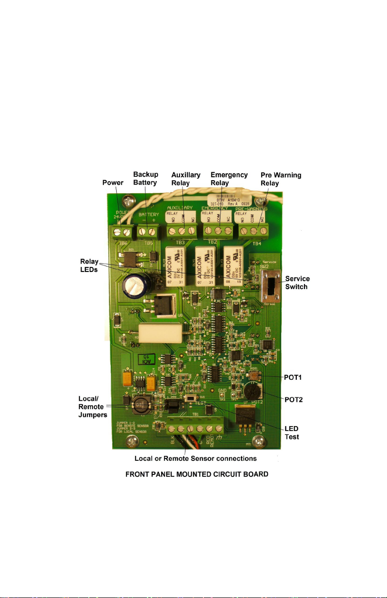
The detector can be set to one of two modes: normal operating mode
or service mode. The detector is in normal operating mode when the
service Switch is in the “Normal” position. When the service switch
is in the “Service” position, the detector continues to function as
usual, however the alarm, pre-alarm, and auxiliary relays are
disabled. This allows the detector to be serviced, tested, and
calibrated without tripping the alarm relays and setting off the alarms.
When the detector is in the service mode, the “Service” LED on the
front panel flashes yellow. After 30 minutes in service mode, the
“Minimal Contamination” and “Early Warning” LEDs will also be lit.
This is done as a reminder to set the service switch back to the
“Normal” mode.
A
Ad
dj
ju
us
st
ta
ab
bl
le
e
A
Al
la
ar
rm
m
P
Po
ot
te
en
nt
ti
io
om
me
et
te
er
r
There is one adjustment potentiometer that is provided to set the
Alarm set point. The Pre-Alarm (Early Warning) is adjusted at the
factory and ‘locked’ into place. The Alarm set point is also pre-set at
the factory but is field adjustable. The adjustment procedure is in the
“INSTALLATION AND SET-UP” section, on page 16.
L
LE
ED
D
T
Te
es
st
t
B
Bu
ut
tt
to
on
n
Pressing the momentary LED Test button will cause all LED’s to
light to up and all three relays to de-energize to confirm that they are
functional.
L
Lo
oc
ca
al
l/
/R
Re
em
mo
ot
te
e
J
Ju
um
mp
pe
er
rs
s
JMPR1 and JMPR2 convert from a local (enclosure mounted) sensor
to a remote sensor.For a local sensor, both jumpers must connect
pins 2 to 3, the far-right position when viewed as shown in the picture
on page 8. For a remote sensor, both jumpers must connect pins 1 to
2, the far-left position when viewed as shown in the picture on page
7.

Page 9
Rev. 4.2 4/10/2020
Copyright © 2019 by Cool Air Incorporated. All rights reserved.
R
Re
el
la
ay
y
L
LE
ED
D’
’s
s
Two green LED’s (see page 7) indicate that the relays are energized.
LED 9, to the left of the relays, indicates that Alarm and Auxiliary
relays are energized. LED 10, to the right of the relays indicates that
the Pre-Warning relay is energized.
E
En
nc
cl
lo
os
su
ur
re
e-
-M
Mo
ou
un
nt
te
ed
d
C
Co
om
mp
po
on
ne
en
nt
ts
s
The enclosure-mounted components include a AC to DC converter
for 100 to 240 VAC, 50/60 Hz operation. An optional back-up
battery can be installed in the location shown and wired to the front-
panel circuit board “Battery” terminal.
P
Po
ow
we
er
r
S
Su
up
pp
pl
ly
y
WARNING: RISK OF ELECTRIC SHOCK. DO NOT
REMOVE COVER. NO USER SERVICEABLE
PARTS INSIDE. REFER TO QUALIFIED SERVICE
PERSONNEL.
AVIS: RISQUE DE CHOC ELECTRIQUE. NE PAS
ENLEVER LE COUVERCLE. AUCUN ENTRETIEN
DE PIECES INTERIEURES PAR L'USAGER.
CONFIER L'ENTRETIEN AU PERSONNEL
QUALIFIE.

Page 10
Rev. 4.2 4/10/2020
Copyright © 2019 by Cool Air Incorporated. All rights reserved.
Power for the LBW-50 must be a nominal 100 to 240 Volts AC,
50/60 Hz, 16 VAC, or 24 VDC. The 100 to 240 Volts AC power is
connected to the AC to DC converter mounted on the back panel of
the enclosure. The 16 VAC or 24 VDC power is connected directly
to the “Power” terminals on the upper left-hand corner of the front
panel mounted circuit board. A safety ground terminal is also
provided on the back panel.
R
Re
el
la
ay
ys
s
The detector has three miniature printed circuit board relays: The
Alarm, Pre-Alarm (Early Warning), and the Auxiliary relays. The
Auxiliary relay operates at the same time as the Alarm relay. In the
normal operating mode, the relays are energized in a normally-open
state. If a loss of power to the detector occurs, the relays will de-
energize and the alarms, if connected, will activate.
R
Re
el
la
ay
y
S
St
ta
at
tu
us
s
L
LE
ED
D’
’s
s
Each relay has a surface-mounted LED associated with it that
indicates the status of the relay. A relay is energized (a non-alarm
condition) when its LED is lighted (green), and de-energized (an
alarm condition) when the LED is not lit.
E
Ex
xt
te
er
rn
na
al
l
C
Co
on
nn
ne
ec
ct
ti
io
on
ns
s
Contacts for external connections:
•Auxiliary Relay contacts
•Alarm Relay contacts
•Pre-Alarm (Early Warning) Relay contacts

Page 11
Rev. 4.2 4/10/2020
Copyright © 2019 by Cool Air Incorporated. All rights reserved.
Wiring Diagram: LBW-50
Installation wiring diagrams for the LBW-50.The 100 to 240 VAC
diagram is shown below, and the 24 VAC or 24 VDC diagram is on
page 12.

Page 12
Rev. 4.2 4/10/2020
Copyright © 2019 by Cool Air Incorporated. All rights reserved.

Page 13
Rev. 4.2 4/10/2020
Copyright © 2019 by Cool Air Incorporated. All rights reserved.
I
IN
NS
ST
TA
AL
LL
LA
AT
TI
IO
ON
N
A
AN
ND
D
S
SE
ET
TU
UP
P
Caution: Do not apply power to the detector until instructed to
do so.
The detector comes with four mounting feet, packaged in the detector
enclosure for shipment. Use the directions that accompany the
mounting feet for mounting the detector enclosure.
The detector should be mounted in a location where ammonia leaks
are most likely to occur, such as near valve groups, compressors, and
refrigeration coils. Be sure the detector is visible and easily
accessible. Avoid locating the detector where it might be damaged
by forklift traffic and/or any other types of external activity. In
washdown areas, please make sure the sensor is protected from
washdown by installing our optional ABS wash-down tube. It is
important not to install the detector (specifically the sensor) in
designated smoking areas, as even a minute concentration of smoke
will set off the alarm.
When power is first applied to the detector in the field, it will
immediately go into Alarm status and the LED’s will indicate a large
ammonia concentration. This is normal. When the sensor warms to
normal operating temperature (usually about a minute) the detector
will return to a non-alarm status. For this reason, the detector must
be placed in service mode before applying power to the detector
to avoid nuisance alarms.
Once the LED’s are no longer lit up, set the service switch back into
the normal mode.
The detector is tested, adjusted, and calibrated at the factory. To field
adjust the Alarm set point of the detector for a specific installation,
follow the steps below.
1. Open the detector enclosure and place the detector in service
mode by sliding the service switch to the “Service” position.
2. Apply power to the detector and allow the sensor to warm up to
normal operating temperature (at normal operating temperature,
all LEDs will be unlit).
3. Hold the desired ammonia test bottle over the sensor head.

Page 14
Rev. 4.2 4/10/2020
Copyright © 2019 by Cool Air Incorporated. All rights reserved.
4. Adjust the Alarm set point by adjusting the potentiometer labeled
‘POT2’ clockwise to increase the sensitivity and counter-
clockwise to decrease the sensitivity.
5. Slide the service switch back to the ‘Normal’ setting.
6. For testing and calibrating the leak detector, see the “TESTING
& CALIBRATION” section on page 19-22.
C
CO
ON
NN
NE
EC
CT
TI
IN
NG
G
T
TH
HE
E
E
EL
LE
EC
CT
TR
RO
OC
CH
HE
EM
MI
IC
CA
AL
L
S
SE
EN
NS
SO
OR
R
Connect wire 3 to “BLK” terminal
Connect wire 2 to “GRN” terminal
Connect wire 1 (wire with blue stripe) to “WHT” terminal

Page 15
Rev. 4.2 4/10/2020
Copyright © 2019 by Cool Air Incorporated. All rights reserved.
Remote Sensing
Remote Sensing allows the ammonia sensor to be located remotely
from the LBW-50. Remember, there is only one sensor per leak
detector.
The wiring diagram below shows the connections from the LBW-50
to the Remote Sensor. All connections to the Remote Sensor are
made at the LBW-50 terminal strip on the Front Panel Circuit Board
using 4 conductor shielded cable. Note specifically that the RED
WIRE CONNECTS TO THE RED REM TERMINAL AND DOES
NOT CONNECT TO THE ‘RED’ TERMINAL. Also, the shield and
or drain conductor connects to the GRN terminal along with the
Green wire on the LBW-50 only (do not connect in the Remote
Sensor).
The Remote Sensor device is pictured next to the wiring diagram.
Please request special documentation for remote sensing
with an electrochemical sensor.

Page 16
Rev. 4.2 4/10/2020
Copyright © 2019 by Cool Air Incorporated. All rights reserved.
Remote Alarm Installation
Remote Alarm allows for an audible and visible alarm of the LBW-50
at a local or remote location.
The wiring diagram below shows the connections from the LBW-50
to the Remote Alarm. Power for the Remote Alarm is derived from
the 16 VAC or 24 VDC ‘Power’ terminal strip on the LBW-50 Front
Panel Circuit Board. An Alarm signal is derived from the LBW-50
enclosure-mounted circuit board.
The Remote Alarm device is pictured next to the wiring diagram.
Backup Battery Testing, Installation and Replacement
The LBW50 can be supplied with an optional Backup Battery from
Cool Air Incorporated. This backup supply is good for approximately
1 ½ hours of operating time. During normal operation, the backup
battery is not used but is kept trickle charged. In the event of a power
failure, the unit will seamlessly operate from the back-up battery.
To test an existing or new battery installation, simple disconnect the
leak detector power supply. The unit should stay in normal operation
and not turn off. If the unit turns off, check to make sure that the red
and black wires are secure on the battery terminals and the circuit

Page 17
Rev. 4.2 4/10/2020
Copyright © 2019 by Cool Air Incorporated. All rights reserved.
board terminals. If the wiring is good, the battery should to be
replaced.
If the back-up battery needs to be replaced because it has either
failed, or will not keep a charge, a new back-up battery can be
ordered through your local leak detector supplier or directly from
Cool Air Incorporated. Prior to removing the old battery, disconnect
the leak detector power supply, remove the black and red wires from
the battery terminals, cut the wire cable strap (used primarily for
shipping), and remove the battery from the Velcro mounting pad.
Install the new battery onto the Velcro mount pad, remove the battery
protector caps, plug the black wire into the black terminal, plug the
red wire to the red terminal, and reconnect the leak detector power
supply. Allow 24-hours of leak detector operation time before testing
the new battery.
A
Am
mm
mo
on
ni
ia
a
L
Le
ea
ak
k
I
In
nd
di
ic
ca
at
ti
io
on
n
In the event of a higher-than-normal ammonia concentration, the
front-panel LEDs will indicate as follows:
If the Ammonia
Concentration… Then the… And…
Equals or exceeds
25 PPM
Red “Minimal
Concentration” LED lights
No other actions
occur
Equals or exceeds
the pre-alarm set
point
Yellow “Early Warning”
LED lights
The pre-alarm
relay trips
Continues to
increase above the
pre-alarm set point
First red “Progressive”
LED lights
No other actions
occur
Equals or exceeds
the alarm set point Red “Alarm” LED flashes
The alarm and
auxiliary relays
trip
After an alarm, the alarm and auxiliary relays will automatically reset
when the ammonia concentration falls below the alarm set point, and
◄ INCREASING ◄ CONCENTRATION ◄

Page 18
Rev. 4.2 4/10/2020
Copyright © 2019 by Cool Air Incorporated. All rights reserved.
the pre-alarm relay will automatically reset when the ammonia
concentration falls below the pre-alarm set point.
T
TE
ES
ST
TI
IN
NG
G
A
AN
ND
D
C
CA
AL
LI
IB
BR
RA
AT
TI
IO
ON
N
(
(w
wi
it
th
h
s
so
ol
li
id
d
s
st
ta
at
te
e
s
se
en
ns
so
or
r)
)
It is recommended the detector(s) be tested at least once a month in
critical areas and once a quarter in non-critical areas to ensure they
are operating correctly. Also, the detector must be calibrated at least
once a year to ensure it is detecting and displaying ammonia
concentration accurately. At the time of calibration, you must use a
new test bottle of ammonia that can be purchased from Cool Air Inc.
or their distributors. If a new ammonia sensor is installed, the detector
must be recalibrated. All tests and calibrations must be documented.
TESTING:
To test the detector, follow these steps:
1. Open the detector enclosure and slide the service switch to the
“SERVICE” position, if needed. This step deactivates the Early
Warning, Alarm, and Auxiliary relays so that any attached strobe
lights, horns, and/or monitoring systems are not activated. In
some applications, if alarming is required, leave the service
switch in the “NORMAL” position.
2. Hold a sample bottle of ammonia of concentration over the
sensor.
3. Check the following:
•LEDs on the front display panel light up from the
bottom to the top.
4. Remove the ammonia sample.
Wait until the ammonia concentration reading is below the
pre- Alarm set point, then slide the service switch to the
“NORMAL”
Position and close the detector enclosure. Remember, this step is
only
Required if the service switch was turned to the “SERVICE”
position in
Step # 1 above. Testing is now complete.

Page 19
Rev. 4.2 4/10/2020
Copyright © 2019 by Cool Air Incorporated. All rights reserved.
CALIBRATION:
1. Visually inspect the leak detector for any corrosion, damage,
etc. that could possibly affect the calibration procedure.
2. Make sure that the leak detector is powered up for a
minimum of 8-hours before the calibration procedure is
performed.
3. Slide the service switch to the “SERVICE” position. This
step deactivates the Early Warning, Alarm, and Auxiliary
relays so that any attached strobe lights, horns, and/or
monitoring systems are not activated. In some applications,
if alarming is required, leave the service switch in the
“NORMAL” position.
4. Place a new ammonia test bottle over the sensor and after
30-45 seconds (slightly longer in coolers & freezers) the top
LED lamp (large lamp) shall light up. Also, the Alarm and
Auxiliary relays shall de-energize. Remember, during the
calibration procedure, the Early Warning LED lamp (amber
lamp) will light up, and the Early Warning relay shall de-
energize. This is a factory set, non-adjustable setting.
5. To fine tune the Alarm set point, adjust the POT2
potentiometer (large potentiometer) until the Alarm LED
lamp just lights up and the relays de-energize. Adjusting
clockwise shall cause the LED lamps to light up from the
bottom to the top. Adjusting counterclockwise shall cause
the LED lamps to turn off from the top to the bottom.
6. Slide the service switch to the “NORMAL” position. this
step is only required if the service switch was turned to the
“SERVICE” position in step # 4 above.
7. We recommend this calibration to be performed once a year
or whenever the sensor has been replaced. Use a new
ammonia test bottle. These can be purchased from your
local Cool Air Incorporated distributor or directly from the
manufacturer.
This manual suits for next models
2
Table of contents
Other Cool Air Gas Detector manuals