Cool Air LBW-420-RLV User manual

Models
0 to 10% Vent Line SENSOR ONLY
LBW-420-RLV-% 24VDC (optional 100 to
240VAC)
FIRMWARE 12


Firmware version 12
Page | 1
Rev. 10-1 10-14-2022
Copyright © 2020 by Cool Air Incorporated. All rights reserved.
PROGRAMMING AND OPERATION ................................................
16
PROGRAMMING THE AMMONIA HI-ALARM AND LOW ALARM SET
POINTS ...................................................................................................
16
PROGRAMMING THE 4-20 MARANGE ...................................................
17
SETTING THE SERVICE MODE TIMEOUT ..............................................
18
SETTING THE AUXILIARY RELAY PAIRING...........................................
18
SETTING THE RELAY LATCHING............................................................
19
RE-SETTING A LATCHED RELAY ...........................................................
19
SPECIFICATIONS ................................................................................... 2
IMPORTANT—READ THIS FIRST ...................................................... 3
CAUTIONS ................................................................................................ 3
INTRODUCTION ..................................................................................... 3
STANDARD FEATURES ......................................................................... 4
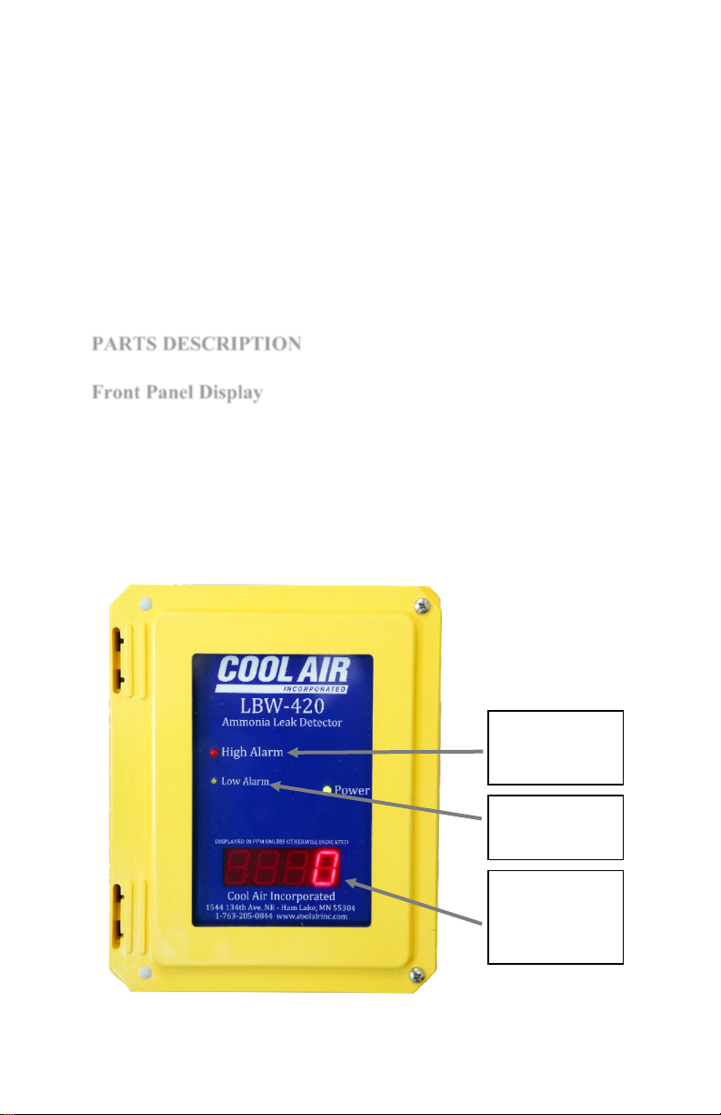
PARTS DESCRIPTION............................................................................ 5
FRONT PANEL DISPLAY .......................................................................... 5
AMMONIA SENSOR .................................................................................. 6
FRONT PANEL-MOUNTED CIRCUIT BOARD ........................................... 6
SERVICE SWITCH (SERVICE MODE) ....................................................... 7
THE “ENTER”, “UP”, AND “DOWN” PUSHBUTTONS................................. 7
ROTARY SELECTOR SWITCH .................................................................. 7
ENCLOSURE-MOUNTED CIRCUIT BOARD............................................. 10
POWER (LBW-420) ............................................................................... 10
JUMPER J3, AMMONIA SIGNAL (LBW-420-1 ONLY)............................. 10
RELAYS.................................................................................................. 11
RELAY STATUS LEDS............................................................................ 11
EXTERNAL CONNECTIONS .................................................................... 11
4–20 MAANALOG OUTPUT ................................................................... 12
INSTALLATION AND SETUP ............................................................. 15
TABLE OF CONTENTS

Firmware version 12
Page | 2
Rev. 10-1 10-14-2022
Copyright © 2020 by Cool Air Incorporated. All rights reserved.
SPECIFICATIONS
ERROR CODES ....................................................................................... 19
MESSAGE CODES ................................................................................... 19
4-20 MAERROR INDICATION ................................................................ 20
TEST AND CALIBRATION .................................................................. 20
TESTING THE DETECTOR ...................................................................... 20
CALIBRATING THE DETECTOR.............................................................. 22
TECHNICAL SUPPORT ....................................................................... 24
WARRANTY ........................................................................................... 25
Ammonia Detection
Sensitivity
.1 to 10%
Display
0.8”, 7-segment LED, 2-digit
Controls
Service mode jumper
Enter, Up, and Down pushbuttons
Rotary selector switch
Jumper
Ammonia Sensor – Catalytic Bead
*Selectivity to NH3
*Linear output
*Long life
*Stable baseline
Relays
Alarm, pre-alarm, and auxiliary (see pairing aux relay)
Form C (SPDT), fail safe
Contact rating: 5A, 120 VAC or 24 VDC
Outputs
Contacts for: alarm, pre-alarm, and auxiliary relays, and external temperature sensor
4-20 mA DC, conforming to S50.01 ratings, Type 2L and Type 2H
Operating Temperature
-40°F to 130°F
Operating Humidity
5% to 80% RH, non-condensing
Power Requirements
LBW-420-RLV-%
24Volts DC, 21.6 – 26.4, +/- 10%
0.5 Amps max.
Dimensions
9½” H x 8” W x 4½” D
Weight
6 lbs.
Enclosure
NEMA 4X rated, UL listed
Pollution Degree
1

Firmware version 12
Page | 3
Rev. 10-1 10-14-2022
Copyright © 2020 by Cool Air Incorporated. All rights reserved.
PLEASE READ AND UNDERSTAND THIS SECTION
BEFORE INSTALLING AND OPERATING THE LBW-
420 DETECTOR.
CAUTION:
INTRODUCTION
WARNING: RISK OF ELECTRIC SHOCK. DO NOT
REMOVE COVER. NO USER SERVICEABLE
PARTS INSIDE. REFER TO QUALIFIED SERVICE
PERSONNEL.
AVIS: RISQUE DE CHOC ELECTRIQUE. NE PAS
ENLEVER LE COUVERCLE. AUCUN ENTRETIEN
DE PIECES INTERIEURES PAR L'USAGER.
CONFIER L'ENTRETIEN AU PERSONNEL
QUALIFIE.
After applying power, test the detector to ensure it is operating
correctly. Be sure the detector has been powered for at least 20
minutes before testing.
Do not store this manual inside the detector, as this
might result in damage to components from excessive
heat.
The Cool Air Incorporated LBW-420-RLV-% Detector is a state-of-
the-art ammonia leak detector that detects and displays ammonia
concentrations of .1 to 9.9%. It comes equipped with a long-life
ammonia sensor that has a quick and accurate response to ammonia
concentrations.
The Cool Air Incorporated LBW-420-RLV-% has a fully isolated
DC to DC power supply, allowing the LBW-420-RLV-% to be
IMPORTANT—READ THIS FIRST

Firmware version 12
Page | 4
Rev. 10-1 10-14-2022
Copyright © 2020 by Cool Air Incorporated. All rights reserved.
STANDARD FEATURES
powered from the same DC supply as the 4-20 mA monitoring
circuits without concern for ground isolation.
The LBW-420-RLV-% requires a DC supply voltage between 18
and 36 volts.
The LBW-420-RLV-% can be configured to supply power to the 4-
20 mA circuit(s) or can operate as a fully isolated 4-20 mA sensor.
Refer to 4–20 mA Analog Outputs for more details.
The Cool Air Incorporated LBW-420-RLV-% can be optionally
equipped with an AC to DC converter to allow operating the
detector with 100 to 240VAC input.
All LBW-420’s come with these additional standard features:
•
Programmable Hi Alarm and Low-Alarm set points
•
Selectable Service Mode timeout
•
4-20 mA analog output signals, for ammonia which can
communicate directly with computer systems such as
PLC’s
•
Normally-open, normally-closed contacts for
communicating with common industry alarm systems,
operating auxiliary equipment such as exhaust fans, king
valves, compressors, and additional alarm systems.
•
A NEMA 4X, UL-listed enclosure.
•
Auxiliary contacts for can be set to operate as an indication
of an error only, error and active with low alarm relay or
error and active with alarm relay.

Firmware version 12
Page | 5
Rev. 10-1 10-14-2022
Copyright © 2020 by Cool Air Incorporated. All rights reserved.
PARTS DESCRIPTION
Front Panel Display
The LBW-420-RLV-% is only available with remote sensing;
•
LBW-RL-RS-50-% - % RLV Remote sensor with 50' cable
•
LBW-RL-RS-100-% - % RLV Remote sensor with 100'
cable
•
LBW-RL-RS-% - LBW-420/50 % RLV Remote sensor no
Cable
•
LBW-LT-RL-RS-5-% - LBW-50 or 420 % relief line
remote sensor with 5 ft. of Liquidtite conduit
The front panel display is comprised of a digital display and a series
of labeled indicating LED’s. The seven-segment, four-digit display
indicates a variety of information, such as ammonia concentration
and external temperature (if an external temperature sensor is in
use), and more, depending on the position of the rotary selector
switch. Ammonia concentration is displayed in percentage. The
LEDs provide an indication of alarm status at a glance.
Four-digit seven seg ment display.
In normal operating mode this will
display the ammonia concentration
in percentage of volume (%). It will
also be use in setting options and
calibration. Optionally it can display
temperature.
Low Alarm indication
Pre-Alarm Relay will be
active when this is on.
Hi Alarm indication
Alarm Relay will be active
when this is on.

Firmware version 12
Page | 6
Rev. 10-1 10-14-2022
Copyright © 2020 by Cool Air Incorporated. All rights reserved.
Front Panel-Mounted Circuit Board
The detector comes with a Catalytic Bead, long-life sensor that has
a good selectivity and a quick response to high concentrations of
ammonia. The sensor is temperature compensated and is protected
by an inexpensive pre-filter that is easy to replace.
The front panel-mounted circuit board contains the controls
necessary for programming and operating the detector. Each
control is described in detail below. When the detector enclosure is
open, this circuit board is on the left, attached to the front panel.
NOTE: The service switch may be a jumper instead of the switch.
Ammonia Sensor

Firmware version 12
Page | 7
Rev. 10-1 10-14-2022
Copyright © 2020 by Cool Air Incorporated. All rights reserved.
The “ENTER”, “UP”, and “DOWN” Pushbuttons
Rotary Selector Switch
The detector can be set to one of two modes: normal operating
mode or service mode. The detector is in normal operating mode
when the service jumper is in the “OFF” position. When the service
jumper is in the “ON” position, the detector continues to function as
usual, however the alarm, pre-alarm, and auxiliary relays are
disabled as well as the 4 to 20mA signal is set to 4ma (0%). This
allows the detector to be serviced, tested, and calibrated without
tripping the alarm relays and setting off alarms.
When the detector is in the service mode, the display will alternate
between the sensor reading in % and “SE” (service jumper “on”,
Switch position 0 or 1). This is done as a reminder to set the jumper
back to “off” when service is done. If the service jumper is not
returned to off, it will automatically return to an as off state after a
selected amount of time. The factory default is 8 Hours.
See “Setting the Service Mode Timeout”
The “UP” and “DOWN” buttons are used for setting the digital
display to the desired value, and the “ENTER” button is used for
programming a value previously set on the digital display. These
buttons are used when programming: the set points, the external
temperature sensor installation status, they are also used during
calibration of the detector.
The rotary selector switch (labeled “MENU SELECT” on the front
panel-mounted circuit board) is used for performing functions such
as:
•
Setting the information displayed on the front panel
•
Programming set points
•
Displaying system information
•
Calibrating the detector
Service Jumper (Service Mode)

Firmware version 12
Page | 8
Rev. 10-1 10-14-2022
Copyright © 2020 by Cool Air Incorporated. All rights reserved.
When the detector is in operation, this switch is typically set to
position “0” to continuously display ammonia concentration.
Use the following chart to select the switch position for the desired
function:
To:
Set the Rotary
Selector Switch to:
Display ammonia concentration in %
0
Display ammonia concentration in %
1
Display the firmware revision
2
Program the ammonia High alarm set point
3
Program the ammonia Low alarm set point
4
Display ammonia concentration in % (See
Section Testing the Detector)
5
Auxiliary Relay latching Yes/No
6
Pre-Alarm (low alarm) Relay latching
Yes/NO
7
Alarm Relay (High Alarm) Latching Yes/No
8
Factory Use
9
Note: If the rotary selector switch is left in a position other than
“0” or “1” and/or the “SET1” jumper is left on for more than 5
minutes without pressing an “UP” or “DOWN” button, the digital
display will begin to display ammonia concentration. If this
happens, return the selector switch to the “0” position and remove
the “SET1” jumper, then set the switch to the desired position. For
example, if you set the rotary selector switch to position “3” to
program the alarm set point, and if, after 5 minutes of inactivity the
display reverts to displaying ammonia concentration, move the
switch to “0”, then back to “3” to continue programming the alarm
set point.
Caution: Before closing the detector enclosure, be sure to
return the rotary selector switch to position “0” or
“1” to correctly display ammonia concentration.

Firmware version 12
Page | 9
Rev. 10-1 10-14-2022
Copyright © 2020 by Cool Air Incorporated. All rights reserved.
Additional functions are available through the rotary selector switch
when the jumper (labeled “SET1”), located below the rotary
selector switch on the front panel-mounted circuit board, is
installed:
To:
Set the Rotary
Selector Switch to:
“- “Future use
1
Display the firmware revision
2
Program the ammonia sensor 4 – 20mA Range
3
Set the Service Mode Time out
4
“- “Future use
5
Sets the AUX relay pairing
6
“- “Future use
7
Calibrate the detector fine adjust
8
Calibrate the detector course adjust
9
Note: If the rotary selector switch is left in a position other than
“0” or “1” and/or the “SET1” jumper is left on for more than 5
minutes without pressing an “UP” or “DOWN” button, the digital
display will begin to display ammonia concentration. If this
happens, return the selector switch to the “0” position and remove
the “SET1” jumper, then set the switch to the desired position. For
example, if you set the rotary selector switch to position “3” to
program the alarm set point, and if, after 5 minutes of inactivity the
display reverts to displaying ammonia concentration, move the
switch to “0”, then back to “3” to continue programming the alarm
set point.

Firmware version 12
Page | 10
Rev. 10-1 10-14-2022
Copyright © 2020 by Cool Air Incorporated. All rights reserved.
Power
Jumper J3, Ammonia signal
The enclosure-mounted circuit boards differ between the LBW-
420/-2 and the LBW-420-1 to accommodate the differing power
connections. All other connections are identical. The Enclosure
Mounted Circuit board contains the relays, output contacts and
termination points for connecting to external equipment. When the
detector enclosure is open, this circuit board is on the rear wall of
the enclosure. The enclosure-mounted circuit board is shown in the
following two pictures and described in detail below. NOTE: This
detector does not support a 4 to 20mA output for the temperature
sensor.
Power for the LBW-420-RLV-% must be a DC voltage between 18
and 30 volts with a current rating of at least 0.5 amps at 24 volts.
Power is connected to terminal block J2.
Jumper J3 (ammonia signal) configures the LBW-420-RLV-% to
use either an external power supply for the Ammonia 4-20 mA
circuit or to use an on board 18 to 30-volt DC supply for the 4-20
mA circuits. With the jumper in the leftmost position, connecting
Enclosure-Mounted Circuit Board

Firmware version 12
Page | 11
Rev. 10-1 10-14-2022
Copyright © 2020 by Cool Air Incorporated. All rights reserved.
Relays
Relay Status LEDs
External Connections
pins 2 to 3 (as shown in the picture on the next page) 4-20mA
power is supplied by the on-board supply.
With the jumper in the rightmost position, connecting pins 2 to 1
(opposite of picture) 4-20 mA power must be supplied by an
external supply.
Jumpers Required
Jumpers J3 must be installed in either position. If the jumper is
removed, the 4-20 mA circuit(s) will not function.
The detector has three miniature printed circuit board relays: the
alarm, pre-alarm (early warning), and the auxiliary relays. The
auxiliary relay operates as selected. (See pairing the Aux Relay)
The factory default is for the auxiliary relay to operate only when
there is an “Err” (error) with the detector. In the normal operating
mode, the relays are energized in a normally-open state. If a loss of
power to the detector occurs, the relays will de-energize and the
alarms, if connected, will sound.
Each relay has a surface-mounted LED associated with it that
indicates the status of the relay. A relay is energized (a non-alarm
condition) when its LED is lighted (green), and de-energized (an
alarm condition) when the LED is not lighted.
Contacts for external connections:
•
4–20 mA outputs for ammonia level
•
Auxiliary Relay contacts
•
External temperature sensor input (not available on
this model)
•
Alarm Relay contacts (Hi Alarm)
•
Pre-alarm Relay contacts (Low alarm)
•
DC Power

Firmware version 12
Page | 12
Rev. 10-1 10-14-2022
Copyright © 2020 by Cool Air Incorporated. All rights reserved.
The detector has a 4-20 mA analog output that allows it to
communicate with external devices such as computers, PLCs, and
digital displays. The output conforms to ISA S50.01 ratings, Type
2L and Type 2H (two-wire).
The ammonia level detector output current (TB2, “Sensor 4-
20mA” terminals on lower left of Enclosure Mounted Circuit
Board) is proportional to ammonia % with the proportionality
constant dependent on the range. The % value can be determined
using one of the following formulae:
% NH3 = .041667 (I – 4) 0 to 1% Range
% NH3 = .083334 (I – 4) 0 to 2%Range
% NH3 =.4166667(I – 4) 0 to 10% Range
Where % NH3 equals ammonia concentration in percent and I equal
the output current in mA. For example, if the current is 4 mA, then
the ammonia concentration is 0 %. If the current is 20 mA, then the
ammonia concentration is 1% (1% range), 2% (2% range), and 10%
(10% range)
4–20 mA Analog Outputs

Firmware version 12
Page | 13
Rev. 10-1 10-14-2022
Copyright © 2020 by Cool Air Incorporated. All rights reserved.
Wiring Diagram:
For this configuration, with the jumper J3 in the leftmost position
(which connects pins 2 & 3) power for the 4-20 mA circuit is
provided by the LBW-420-1. This circuit is shown below. The
power supply must supply all power for the LBW-420-1 plus the 4-
20 mA circuit. Refer to the specifications page for the power
requirements for the LBW-420-1. The voltage drop across the
detector and the receiver together must not exceed the power supply
voltage. This circuit is shown in figure 2 below:
Fig 2

Firmware version 12
Page | 14
Rev. 10-1 10-14-2022
Copyright © 2020 by Cool Air Incorporated. All rights reserved.
Wiring Diagram: With (2) – 24 VDC Power Supplies
In this configuration, with the jumper J3 in the rightmost position
(which connects pins 1 & 2), power for the LBW-420-1 is supplied
by the 24 VDC power supply #1 only. The power supply must
supply all power for the LBW-420-1. Refer to the specifications
page for the power requirements for the LBW-420-1. The power
for the 4-20 mA circuit is supplied by the 24 VDC power supply #2.
The 4-20 mA circuit is a simple series circuit that includes the LBW
detector, a power supply, and the receiving device. It is
recommended that a 24 VDC low-noise power supply be used for
this application, although power supplies providing a minimum of
10 VDC to a maximum 30 VDC can be used. The voltage drop
across the detector and the receiver together must not exceed the
power supply voltage. This circuit is shown in Figure 3 below:
Fig 3
The maximum allowable resistance in the receiving device must not
exceed Rmax using this formula:
Rmax = 50 (Vs – 7.5)

Firmware version 12
Page | 15
Rev. 10-1 10-14-2022
Copyright © 2020 by Cool Air Incorporated. All rights reserved.
INSTALLATION AND SETUP
Where Vs is the supply voltage in volts DC for the 4-20 mA circuit.
For example, with a supply voltage of 24 VDC, the maximum
allowable resistance is 825 Ω.
Caution: Do not apply power to the detector until instructed to
do so.
The detector comes with four mounting feet, packaged in the
detector enclosure for shipment. Use the directions that accompany
the mounting feet for mounting the detector enclosure.
Be sure the detector is visible and easily accessible. Avoid locating
the detector where it might be damaged.
When power is applied to the detector, it may go into alarm status
and the display will show an unusually large ammonia
concentration. This is normal. When the sensor warms to normal
operating temperature (usually about a minute) the detector will
return to a non-alarm status. For this reason, the detector should
be placed in service mode before applying power to the detector
to avoid nuisance alarms.
The detector is calibrated and programmed at the factory. To
program the detector for its specific installation, follow these steps
in the order given:
1.
Open the detector enclosure and place the detector in service
mode by moving the service jumper to the “ON” position.
2.
Apply power to the detector and allow the sensor to warm to
normal operating temperature (at normal operating temperature,
the display will read “0” and all Alarm LEDs will be unlit).
3.
Program the ammonia Low alarm and High alarm set points.
See the next section on programming the ammonia Low alarm
and high alarm set points.
4.
Set the detector to the desired operating display mode (typically
“0” or “1”). See the next section on setting the display mode.
5.
Be sure the displayed ammonia concentration is below the
programmed Low alarm set point Return the detector to normal

Firmware version 12
Page | 16
Rev. 10-1 10-14-2022
Copyright © 2020 by Cool Air Incorporated. All rights reserved.
Programming the Ammonia Hi Alarm and Low Alarm
Set Points
operating mode by moving the service jumper to the “OFF”
position.
6.
Test the detector to ensure it is operating correctly (but allow at
least 20 minutes after power is first applied to the detector
before testing). See the section on testing the detector.
The LBW-420 detector is easy to program and operate. Follow the
instructions in this section to:
•
Program the ammonia alarm set points
•
Set the 4 to 20mA range
•
Set the Aux Relay pairing
•
Set relays latching Yes / No
The Hi alarm set point can be set from .1% to 9.9% in .1%
increments.
The High alarm set point cannot be lower than the Low alarm set
point. When moving the High alarm set point lower it will stop
decreasing when it equals the Low alarm set point.
The Low Alarm set point can be set from .1% to 9.9% in .1%
increments.
The Low alarm set point cannot be higher than the High alarm set
point. If when increasing the Low alarm set point it becomes equal
to the High alarm set point, as you increase the low alarm set point
it will also increase the High alarm set point to always maintain
equal or lower set point.
1.
Open the detector enclosure and move the service jumper to the
“ON” position.
2.
Set the rotary selector switch to position “3” to program the
ammonia the Hi-Alarm set point (ALARM RELAY) or “4” to
program the ammonia Low Alarm set point (PRE-ALARM
RELAY).
PROGRAMMING AND OPERATION

Firmware version 12
Page | 17
Rev. 10-1 10-14-2022
Copyright © 2020 by Cool Air Incorporated. All rights reserved.
3.
Press the “UP” or “DOWN” button until the desired set point
concentration in % is displayed.
4.
Press and hold the “ENTER” button for at least 2 seconds. The
new set point is now programmed.
5.
Return the rotary selector switch to the desired position.
6.
Be sure the ammonia concentration reading is below the
pre-alarm set point, then move the service jumper to the
“OFF” position and close the detector enclosure.
Programming the 4-20 mA range
The ammonia level 4-20 mA signal can be scaled to one of three
ranges, either 0-1%, 0-2%, or 0-10%. The 0 to 1% range is the
default setting.
To program the 4-20 mA range, follow these steps:
1.
Open the detector enclosure and move the service jumper
to the “ON” position.
2.
Install the jumper on the jumper pins (labeled “SET1”)
located below the rotary switch on the front panel-mounted
circuit board.
3.
Set the rotary selector switch to position “3”. The display
will indicate the current range, either “r1” = 0 to 1%, “r2”
= o to 2%, or “r3” 0 to 10%.
4.
Press the “UP” or “DOWN” button until the display
indicates the desired range.
5.
Press and hold the “ENTER” button for at least 2 seconds.
The new range is now programmed.
6.
Remove the jumper and return the rotary selector switch to
the desired position.
7.
Move the service jumper to the “OFF” position and close
the detector enclosure.

Firmware version 12
Page | 18
Rev. 10-1 10-14-2022
Copyright © 2020 by Cool Air Incorporated. All rights reserved.
Setting the Auxiliary Relay Pairing
If the service jumper is not returned to off, you can change how
long the detector stays in service mode before returning to normal
operating mode.
With the SET 1 jumper on and the Rotary Switch in position 4 you
can use the up and down buttons to select either;
1 – After 1 Hour in the on position the detector will return to normal mode.
2 – After 2 Hours in the on position the detector will return to normal
mode.
4 – After 4 Hours in the on position the detector will return to normal
mode.
8 – After 8 Hours in the on position the detector will return to normal
mode.
Once you have selected the desired service mode timeout you must
hold the ENTER button for two seconds before removing the SET 1
jumper or changing the rotary switch.
The auxiliary relay will always activate when there is an error (Err
on the display). In addition, you can select to have the auxiliary
relay paired (activate at the same time) as either the Hi Alarm
(alarm relay) or the Low Alarm (pre-alarm relay).
With the SET jumper on and the Rotary Switch in position 6 you
can use the up and down buttons to select either;
AU – Auxiliary relay is not paired. Activates on errors only.
AL – Auxiliary relay is paired with the Hi Alarm (alarm) relay.
PR – Auxiliary relay is paired with the Low Alarm (pre-alarm) relay.
Once you have selected the desired service mode timeout you must
hold the ENTER button for two seconds before removing the SET 1
jumper or changing the rotary switch.
Setting the Service Mode Timeout
Table of contents
Other Cool Air Gas Detector manuals