Cool Air LBW-420-EC User manual

M
Mo
od
de
el
ls
s
E
EL
LE
EC
CT
TR
RO
OC
CH
HE
EM
MI
IC
CA
AL
L
S
SE
EN
NS
SO
OR
R
O
ON
NL
LY
Y
L
LB
BW
W-
-4
42
20
0-
-E
EC
C
(
(1
11
15
5V
VA
AC
C
p
po
ow
we
er
re
ed
d)
)
L
LB
BW
W-
-4
42
20
0-
-1
1-
-E
EC
C
(
(2
24
4V
VD
DC
C
p
po
ow
we
er
re
ed
d)
)
L
LB
BW
W-
-4
42
20
0-
-2
2-
-E
EC
C
(
(2
23
30
0V
VA
AC
C
p
po
ow
we
er
re
ed
d)
)
Electrochemical Sensor


Page | 1
Rev. 11-5 12/15/2020
Copyright © 2020 by Cool Air Incorporated. All rights reserved.
T
TA
AB
BL
LE
E
O
OF
F
C
CO
ON
NT
TE
EN
NT
TS
S
S
SP
PE
EC
CI
IF
FI
IC
CA
AT
TI
IO
ON
NS
S.................................................................................................2
I
IM
MP
PO
OR
RT
TA
AN
NT
T—
—R
RE
EA
AD
D
T
TH
HI
IS
S
F
FI
IR
RS
ST
T...................................................................3
C
CA
AU
UT
TI
IO
ON
NS
S..............................................................................................................3
I
IN
NT
TR
RO
OD
DU
UC
CT
TI
IO
ON
N...................................................................................................4
S
ST
TA
AN
ND
DA
AR
RD
D
F
FE
EA
AT
TU
UR
RE
ES
S......................................................................................5
P
PA
AR
RT
TS
S
D
DE
ES
SC
CR
RI
IP
PT
TI
IO
ON
N.........................................................................................6
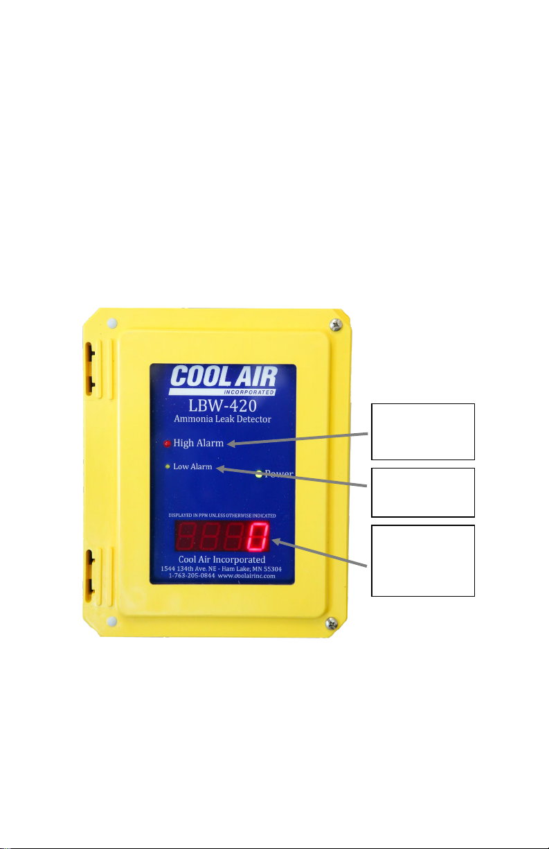
F
FR
RO
ON
NT
T
P
PA
AN
NE
EL
L
D
DI
IS
SP
PL
LA
AY
Y........................................................................................6
A
AM
MM
MO
ON
NI
IA
A
S
SE
EN
NS
SO
OR
R................................................................................................7
F
FR
RO
ON
NT
T
P
PA
AN
NE
EL
L-
-M
MO
OU
UN
NT
TE
ED
D
C
CI
IR
RC
CU
UI
IT
T
B
BO
OA
AR
RD
D.........................................................7
S
SE
ER
RV
VI
IC
CE
E
S
SW
WI
IT
TC
CH
H
(
(S
SE
ER
RV
VI
IC
CE
E
M
MO
OD
DE
E)
).....................................................................8
T
TH
HE
E
“
“E
EN
NT
TE
ER
R”
”,
,
“
“U
UP
P”
”,
,
A
AN
ND
D
“
“D
DO
OW
WN
N”
”
P
PU
US
SH
HB
BU
UT
TT
TO
ON
NS
S.......................................8
R
RO
OT
TA
AR
RY
Y
S
SE
EL
LE
EC
CT
TO
OR
R
S
SW
WI
IT
TC
CH
H................................................................................8
E
EN
NC
CL
LO
OS
SU
UR
RE
E-
-M
MO
OU
UN
NT
TE
ED
D
C
CI
IR
RC
CU
UI
IT
T
B
BO
OA
AR
RD
D..........................................................11
P
PO
OW
WE
ER
R
(
(L
LB
BW
W-
-4
42
20
0)
)............................................................................................11
P
PO
OW
WE
ER
R
(
(L
LB
BW
W-
-4
42
20
0-
-1
1)
).........................................................................................11
J
JU
UM
MP
PE
ER
R
J
J3
3,
,
A
AM
MM
MO
ON
NI
IA
A
S
SI
IG
GN
NA
AL
L
(
(L
LB
BW
W-
-4
42
20
0-
-1
1
O
ON
NL
LY
Y)
).........................................11
R
RE
EL
LA
AY
YS
S...............................................................................................................12
R
RE
EL
LA
AY
Y
S
ST
TA
AT
TU
US
S
L
LE
ED
DS
S.........................................................................................13
E
EX
XT
TE
ER
RN
NA
AL
L
C
CO
ON
NN
NE
EC
CT
TI
IO
ON
NS
S..................................................................................13
4
4–
–2
20
0
M
MA
A
A
AN
NA
AL
LO
OG
G
O
OU
UT
TP
PU
UT
T................................................................................13
I
IN
NS
ST
TA
AL
LL
LA
AT
TI
IO
ON
N
A
AN
ND
D
S
SE
ET
TU
UP
P...........................................................................17
P
PR
RO
OG
GR
RA
AM
MM
MI
IN
NG
G
A
AN
ND
D
O
OP
PE
ER
RA
AT
TI
IO
ON
N..............................................................18
S
SE
ET
TT
TI
IN
NG
G
T
TH
HE
E
D
DE
ES
SI
IR
RE
ED
D
D
DI
IS
SP
PL
LA
AY
Y
M
MO
OD
DE
E.............................................................19
P
PR
RO
OG
GR
RA
AM
MM
MI
IN
NG
G
T
TH
HE
E
A
AM
MM
MO
ON
NI
IA
A
H
HI
I-
-A
AL
LA
AR
RM
M
A
AN
ND
D
L
LO
OW
W
A
AL
LA
AR
RM
M
S
SE
ET
T
P
PO
OI
IN
NT
TS
S.................................................................................................................19
P
PR
RO
OG
GR
RA
AM
MM
MI
IN
NG
G
T
TH
HE
E
E
EX
XT
TE
ER
RN
NA
AL
L
T
TE
EM
MP
PE
ER
RA
AT
TU
UR
RE
E
S
SE
EN
NS
SO
OR
R
I
IN
NS
ST
TA
AL
LL
LA
AT
TI
IO
ON
N
S
ST
TA
AT
TU
US
S.......................................................................................20
PROGRAMMING THE 4-20 MARANGE ................................................................ 21
S
SE
ET
TT
TI
IN
NG
G
T
TH
HE
E
S
SE
ER
RV
VI
IC
CE
E
M
MO
OD
DE
E
T
TI
IM
ME
EO
OU
UT
T...........................................................21
S
SE
ET
TT
TI
IN
NG
G
T
TH
HE
E
A
AU
UX
XI
IL
LI
IA
AR
RY
Y
R
RE
EL
LA
AY
Y
P
PA
AI
IR
RI
IN
NG
G........................................................22
E
ER
RR
RO
OR
R
C
CO
OD
DE
ES
S.....................................................................................................23
M
ME
ES
SS
SA
AG
GE
E
C
CO
OD
DE
ES
S................................................................................................23
4
4-
-2
20
0
M
MA
A
E
ER
RR
RO
OR
R
I
IN
ND
DI
IC
CA
AT
TI
IO
ON
N.............................................................................23
A
AM
MM
MO
ON
NI
IA
A
L
LE
EA
AK
K
I
IN
ND
DI
IC
CA
AT
TI
IO
ON
N.............................................................................24

Page | 2
Rev. 11-5 12/15/2020
Copyright © 2020 by Cool Air Incorporated. All rights reserved.
T
TE
ES
ST
T
A
AN
ND
D
C
CA
AL
LI
IB
BR
RA
AT
TI
IO
ON
N...............................................................................24
T
TE
ES
ST
TI
IN
NG
G
T
TH
HE
E
D
DE
ET
TE
EC
CT
TO
OR
R....................................................................................25
C
CA
AL
LI
IB
BR
RA
AT
TI
IN
NG
G
T
TH
HE
E
D
DE
ET
TE
EC
CT
TO
OR
R...........................................................................26
Z
ZE
ER
RO
O
O
OF
FF
FS
SE
ET
T
A
AD
DJ
JU
US
ST
T.........................................................................................26
WHEN INSTALLING A NEW SENSOR .................................................................... 26
T
TE
EC
CH
HN
NI
IC
CA
AL
L
S
SU
UP
PP
PO
OR
RT
T.....................................................................................28
W
WA
AR
RR
RA
AN
NT
TY
Y.........................................................................................................29
S
SP
PE
EC
CI
IF
FI
IC
CA
AT
TI
IO
ON
NS
S
Ammonia Detection
Sensitivity 0 to 500 PPM
Display 0.8”, 7-segment LED, 4-digit
Controls
Service mode jumper
Enter, Up, and Down pushbuttons
Rotary selector switch
Jumper
Ammonia Sensor - Electrochemical
* High selectivity to NH3
* Small influence by H2S
* Excellent durability to NH3 exposure
* Linear output
* Long life
* Stable baseline
* Unique leak-proof structure
Relays
Alarm, pre-alarm, and auxiliary (see pairing aux relay)
Form C (SPDT), fail safe
Contact rating: 5A, 120 VAC or 24 VDC
Outputs Contacts for: alarm, pre-alarm, and auxiliary relays, and external temperature sensor
4-20 mA DC, conforming to S50.01 ratings, Type 2L and Type 2H
Operating Temperature -10°F to 110°F
Operating Humidity 5% to 95% RH, non-condensing
Power Requirements
L
LB
BW
W-
-4
42
20
0
L
LB
BW
W-
-4
42
20
0-
-2
2
115VAC, 50/60 Hz 230VAC, 50/60 Hz
0.5 Amps max. 0.5 Amps max.
L
LB
BW
W-
-4
42
20
0-
-1
1
24Volts DC, 21.6 – 26.4, +/- 10%
0.5 Amps max.
Dimensions 9½” H x 8” W x 4½” D
Weight 6 lbs.
Enclosure NEMA 4X rated, UL listed
Pollution Degree 1

Page | 3
Rev. 11-5 12/15/2020
Copyright © 2020 by Cool Air Incorporated. All rights reserved.
Approvals
LBW-420 115VAC and
LBW-420-1 24VDC
Tested to UL 61010-1:2004 R7.05
CAN/CSA-C22.2 61010-1:2004
By TUV
Certificate no. CU72090607 01
Options
1. Remote ammonia sensor with box and cable (500 ft. max.)
2. Temperature (F) sensor with cable
3. External back-up battery
4. ABS washdown tube
5. Remote alarm light and horn unit with box, cable, & TEST/NORMAL/SILENCE toggle
switch.
I
IM
MP
PO
OR
RT
TA
AN
NT
T—
—R
RE
EA
AD
D
T
TH
HI
IS
S
F
FI
IR
RS
ST
T
P
PL
LE
EA
AS
SE
E
R
RE
EA
AD
D
A
AN
ND
D
U
UN
ND
DE
ER
RS
ST
TA
AN
ND
D
T
TH
HI
IS
S
S
SE
EC
CT
TI
IO
ON
N
B
BE
EF
FO
OR
RE
E
I
IN
NS
ST
TA
AL
LL
LI
IN
NG
G
A
AN
ND
D
O
OP
PE
ER
RA
AT
TI
IN
NG
G
T
TH
HE
E
L
LB
BW
W-
-
4
42
20
0
D
DE
ET
TE
EC
CT
TO
OR
R.
.
N
No
ot
te
e:
:
T
Th
hi
is
s
m
ma
an
nu
ua
al
l
i
is
s
s
sp
pe
ec
ci
if
fi
ic
c
t
to
o
a
an
nL
LB
BW
W-
-4
42
20
0
w
wi
it
th
h
a
an
n
E
El
le
ec
ct
tr
ro
oc
ch
he
em
mi
ic
ca
al
l
s
se
en
ns
so
or
r
i
in
ns
st
ta
al
ll
le
ed
d,
,
i
it
t
i
is
s
p
po
os
ss
si
ib
bl
le
e
t
to
o
d
do
o
a
a
f
fi
ie
el
ld
d
c
co
on
nv
ve
er
rs
si
io
on
n
t
to
o
a
a
S
So
ol
li
id
d-
-S
St
ta
at
te
e
S
Se
en
ns
so
or
r.
.
C
Co
on
nt
ta
ac
ct
t
C
Co
oo
ol
l
A
Ai
ir
r
I
In
nc
co
or
rp
po
or
ra
at
te
ed
d
s
sa
al
le
es
s
-
-
s
sa
al
le
es
s@
@c
co
oo
ol
la
ai
ir
ri
in
nc
c.
.c
co
om
m
o
or
r
7
76
63
3-
-2
20
05
5-
-0
08
84
44
4
f
fo
or
r
m
mo
or
re
e
i
in
nf
fo
or
rm
ma
at
ti
io
on
n.
.
C
CA
AU
UT
TI
IO
ON
N:
:
WARNING: RISK OF ELECTRIC SHOCK. DO NOT
REMOVE COVER. NO USER SERVICEABLE
PARTS INSIDE. REFER TO QUALIFIED SERVICE
PERSONNEL.
AVIS: RISQUE DE CHOC ELECTRIQUE. NE PAS
ENLEVER LE COUVERCLE. AUCUN ENTRETIEN
DE PIECES INTERIEURES PAR L'USAGER.
CONFIER L'ENTRETIEN AU PERSONNEL
QUALIFIE.
After applying power, test the detector to ensure it is operating
correctly. Be sure the detector has been powered for at least 20
minutes before testing.

Page | 4
Rev. 11-5 12/15/2020
Copyright © 2020 by Cool Air Incorporated. All rights reserved.
Do not store this manual inside the detector, as this
might result in damage to components from excessive
heat.
Adequately cover the detector sensor during washdown and avoid
spraying the washdown liquid directly onto the sensor. If necessary,
an ABS wash down tube is available from the factory.
A nuisance alarm will also occur if the external temperature sensor
installation status is programmed to “F In” (installed) and an
external temperature sensor is not installed.
I
IN
NT
TR
RO
OD
DU
UC
CT
TI
IO
ON
N
The Cool Air Incorporated LBW-420 Family of Detectors is a state-
of-the-art ammonia leak detector that detects and displays ammonia
concentrations of 0 to 500 parts per million (PPM) electrochemical
sensor or 0 to 1000 parts per million (PPM) solid state sensor.
The Cool Air Incorporated LBW-420-2 is a 230VAC powered
version of the LBW-420 ammonia leak detector (115VAC powered
detector). The LBW-420-2 requires an AC supply voltage between
200 and 240 volts AC.
The Cool Air Incorporated LBW-420-1 is a DC powered version of
the LBW-420 ammonia leak detector (AC powered detector). The
LBW420-1 incorporates a fully isolated DC to DC power supply,
allowing the LBW-420-1 to be powered from the same DC supply
as the 4-20 mA monitoring circuits without concern for ground
isolation.
The LBW-420-1 requires a DC supply voltage between 18 and 36
volts DC.
The LBW-420-1 can be configured to supply power to the 4-20 mA
circuit(s) or can operate as a fully isolated 4-20 mA sensor. Refer
to 4
4–
–2
20
0
m
mA
A
A
An
na
al
lo
og
g
O
Ou
ut
tp
pu
ut
ts
s
f
fo
or
r
m
mo
or
re
e
d
de
et
ta
ai
il
ls
s.
.

Page | 5
Rev. 11-5 12/15/2020
Copyright © 2020 by Cool Air Incorporated. All rights reserved.
S
ST
TA
AN
ND
DA
AR
RD
D
F
FE
EA
AT
TU
UR
RE
ES
S
All LBW-420’s come with these additional standard features:
•Programmable Hi Alarm and Low-Alarm set points
•Selectable PPM reading start (0PPM or 25PPM)
•Selectable Service Mode timeout
•4-20 mA analog output signals, for ammonia which can
communicate directly with computer systems such as
PLC’s
•Normally-open, normally-closed contacts for
communicating with common industry alarm systems.
•A NEMA 4X, UL-listed enclosure.
•
•
Spare contacts for operating auxiliary equipment such as
exhaust fans, king valves, compressors, and additional
alarm systems. This relay can be set to operate as an
indication of an error only, error and active with low alarm
relay or error and active with alarm relay.
In addition to the standard features, the LBW-420 and LBW-420-1
can be equipped with these options:
•A remote ammonia sensor with cable allowing the sensor
to be located a maximum of 500 feet away from the
detector.
•An external back-up battery to keep the detector working
during loss of main power.
•External Temperature Sensor (display only NO 4 to 20mA
output)
•An ABS wash-down tube installed over the sensor so that
it does not get wet during washdown.
•A remote alarm light and horn box with/or without a toggle
switch to TEST/NORMAL/SILENCE the alarm.
Contact Cool Air Incorporated technical support for more detailed
information, or for purchasing, any of these options.

Page | 6
Rev. 11-5 12/15/2020
Copyright © 2020 by Cool Air Incorporated. All rights reserved.
P
PA
AR
RT
TS
S
D
DE
ES
SC
CR
RI
IP
PT
TI
IO
ON
N
F
Fr
ro
on
nt
t
P
Pa
an
ne
el
l
D
Di
is
sp
pl
la
ay
y
The front panel display is comprised of a digital display and a series
of labeled indicating LED’s. The seven-segment, four-digit display
indicates a variety of information, such as ammonia concentration
and external temperature (if an external temperature sensor is in
use), and more, depending on the position of the rotary selector
switch. Ammonia concentration is displayed in parts per million
and temperature is displayed in degrees Fahrenheit (“F”). The
LED’s provide an indication of ammonia concentration and alarm
status at a glance.
For information on how the display indicates ammonia
concentrations, see the sections on ammonia leak indication.
Four-digit seven segment display.
In normal operating mode this will
display the ammonia concentration
in parts per million (PPM). It will
also be use in setting options and
calibration. Optionally it can display
temperature.
Low Alarm indication
Pre-Alarm Relay will be
active when this is on.
Hi Alarm indication
Alarm Relay will be active
when this is on.

Page | 7
Rev. 11-5 12/15/2020
Copyright © 2020 by Cool Air Incorporated. All rights reserved.
A
Am
mm
mo
on
ni
ia
a
S
Se
en
ns
so
or
r
The detector comes with an Electrochemical, long-life sensor that
has a high selectivity and a quick response to concentrations of
ammonia. The sensor is temperature compensated and is protected
by an inexpensive pre-filter that is easy to replace.
F
Fr
ro
on
nt
t
P
Pa
an
ne
el
l-
-M
Mo
ou
un
nt
te
ed
d
C
Ci
ir
rc
cu
ui
it
t
B
Bo
oa
ar
rd
d
The front panel-mounted circuit board contains the controls
necessary for programming and operating the detector. Each
control is described in detail below. When the detector enclosure is
open, this circuit board is on the left, attached to the front panel.
NOTE: The service switch may be a jumper instead of the switch.

Page | 8
Rev. 11-5 12/15/2020
Copyright © 2020 by Cool Air Incorporated. All rights reserved.
S
Se
er
rv
vi
ic
ce
e
J
Ju
um
mp
pe
er
r
(
(S
Se
er
rv
vi
ic
ce
e
M
Mo
od
de
e)
)
The detector can be set to one of two modes: normal operating
mode or service mode. The detector is in normal operating mode
when the service jumper is in the “OFF” position. When the service
jumper is in the “ON” position, the detector continues to function as
usual, however the alarm, pre-alarm, and auxiliary relays are
disabled as well as the 4 to 20mA signal is set to 4ma (0PPM). This
allows the detector to be serviced, tested, and calibrated without
tripping the alarm relays and setting off nuisance alarms.
When the detector is in the service mode, the display will alternate
between the sensor reading in PPM and “SEr” (service jumper
“on”). This is done as a reminder to set the jumper back to “off”
when service is done. If the service jumper is not returned to off, it
will automatically return to an as off state after a selected amount of
time. The factory default is 15 minutes.
See “Setting the Service Mode Timeout”
T
Th
he
e
“
“E
EN
NT
TE
ER
R”
”,
,
“
“U
UP
P”
”,
,
a
an
nd
d
“
“D
DO
OW
WN
N”
”
P
Pu
us
sh
hb
bu
ut
tt
to
on
ns
s
The “UP” and “DOWN” buttons are used for setting the digital
display to the desired value, and the “ENTER” button is used for
programming a value previously set on the digital display. These
buttons are used when programming: the set points, the external
temperature sensor installation status, they are also used during
calibration of the detector.
R
Ro
ot
ta
ar
ry
y
S
Se
el
le
ec
ct
to
or
r
S
Sw
wi
it
tc
ch
h
The rotary selector switch (labeled “MENU SELECT” on the front
panel-mounted circuit board) is used for performing functions such
as:
•Setting the information displayed on the front panel
•Programming set points
•Displaying system information
•Calibrating the detector

Page | 9
Rev. 11-5 12/15/2020
Copyright © 2020 by Cool Air Incorporated. All rights reserved.
When the detector is in operation, this switch is typically set to
position “0” to continuously display ammonia concentration, or to
position “1” to display ammonia concentration and an external
temperature (if an external temperature sensor is in use). If the
switch is set to position “1”, the display will alternate between
ammonia concentration and external temperature.
Use the following chart to select the switch position for the desired
function:
To:
Set the Rotary
Selector Switch to:
Display ammonia concentration in PPM
0
Display ammonia concentration in PPM and
external temperature in °F (if an external
temperature sensor is in use)
1
Display the firmware revision
2
Program the ammonia High alarm set point
3
Program the ammonia Low alarm set point
4
Display ammonia concentration in PPM (See
Section Testing the Detector)
5
Factory Use
6
Factory Use
7
Electrochemical Sensor Zero offset
8
Factory Use
9
Note: If the rotary selector switch is left in a position other than “0”
or “1” for more than 5 minutes without pressing an “UP” or
“DOWN” button, the digital display will begin to display ammonia
concentration. If this happens, return the selector switch to the “0”
position, then set the switch to the desired position. For example, if
you set the rotary selector switch to position “3” to program the
alarm set point, and if, after 5 minutes of inactivity the display
reverts to displaying ammonia concentration, move the switch to
“0”, then back to “3” to continue programming the alarm set point.
Caution: Before closing the detector enclosure, be sure to
return the rotary selector switch to position “0” or
“1” to correctly display ammonia concentration, or
ammonia concentration and external temperature.

Page | 10
Rev. 11-5 12/15/2020
Copyright © 2020 by Cool Air Incorporated. All rights reserved.
Additional functions are available through the rotary selector switch
when the jumper (labeled “SET1”), located below the rotary
selector switch on the front panel-mounted circuit board, is
installed:
To:
Set the Rotary
Selector Switch to:
Display ammonia sensor temperature (Solid
State Sensor Only)
1
Zero adjust for the Electrochemical sensor
2
Program the ammonia sensor 4 – 20mA Range
3
Set the Service Mode Time out
4
Set the status of the External Temperature
sensor (installed or not installed)
5
Sets the AUX relay pairing
6
Set the Display start value. 0PPM, 10PPM or
25PPM
7
Select for Solid State Sensor or
Electrochemical Sensor
8
Calibrate the detector
9
Note: If the SET1 jumper is left in the installed position for more
than 5 minutes without pressing an “UP” or “DOWN” button, the
digital display will begin to display ammonia concentration. If this
happens, remove the SET1 jumper and return the selector switch to
the “0” position, then re-install the SET1 jumper and set the switch
to the desired position.

Page | 11
Rev. 11-5 12/15/2020
Copyright © 2020 by Cool Air Incorporated. All rights reserved.
E
En
nc
cl
lo
os
su
ur
re
e-
-M
Mo
ou
un
nt
te
ed
d
C
Ci
ir
rc
cu
ui
it
t
B
Bo
oa
ar
rd
d
The enclosure-mounted circuit boards differ between the LBW-
420/-2 and the LBW-420-1 to accommodate the differing power
connections. All other connections are identical. The Enclosure
Mounted Circuit board contains the relays, output contacts and
termination points for connecting to external equipment. When the
detector enclosure is open, this circuit board is on the rear wall of
the enclosure. The enclosure-mounted circuit board is shown in the
following two pictures and described in detail below. NOTE: This
detector does not support a 4 to 20mA output for the temperature
sensor.
P
Po
ow
we
er
r
(
(L
LB
BW
W-
-4
42
20
0)
)
Power for the LBW-420 must be a nominal 115 Volt AC circuit.
Power for the LBW-420-2 must be a nominal 230 Volt AC circuit.
Power is connected to terminal block J2. A safety ground terminal
is also provided on terminal block J2.
P
Po
ow
we
er
r
(
(L
LB
BW
W-
-4
42
20
0-
-1
1)
)
Power for the LBW-420-1 must be a DC voltage between 18 and 30
volts with a current rating of at least 0.5 amps at 24 volts. Power is
connected to terminal block J2.
J
Ju
um
mp
pe
er
r
J
J3
3,
,
A
Am
mm
mo
on
ni
ia
a
s
si
ig
gn
na
al
l
(
(L
LB
BW
W-
-4
42
20
0-
-1
1
o
on
nl
ly
y)
)
Jumper J3 (ammonia signal) configures the LBW-420-1 to use
either an external power supply for the Ammonia 4-20 mA circuit
or to use an on board 18 to 30-volt DC supply for the 4-20 mA
circuits.

Page | 12
Rev. 11-5 12/15/2020
Copyright © 2020 by Cool Air Incorporated. All rights reserved.
With the jumper in the leftmost position, connecting pins 2 to 3 (as
shown in the picture on the next page) 4-20mA power is supplied
by the on-board supply.
With the jumper in the rightmost position, connecting pins 2 to 1
(opposite of picture) 4-20 mA power must be supplied by an
external supply.
NOTE: This detector does not support a 4 to 20mA output for the
temperature sensor.
J
Ju
um
mp
pe
er
rs
s
R
Re
eq
qu
ui
ir
re
ed
d
Jumpers J3 must be installed in either position. If the jumper is
removed, the 4-20 mA circuit(s) will not function.
R
Re
el
la
ay
ys
s
The detector has three miniature printed circuit board relays: the
alarm, pre-alarm (early warning), and the auxiliary relays. The
auxiliary relay operates as selected. (see pairing the Aux Relay) The
factory default is for the auxiliary relay to operate only when there
is an “Err” (error) with the detector. In the normal operating mode,
the relays are energized in a normally-open state. If a loss of power
to the detector occurs, the relays will de-energize and the alarms, if
connected, will sound.

Page | 13
Rev. 11-5 12/15/2020
Copyright © 2020 by Cool Air Incorporated. All rights reserved.
R
Re
el
la
ay
y
S
St
ta
at
tu
us
s
L
LE
ED
Ds
s
Each relay has a surface-mounted LED associated with it that
indicates the status of the relay. A relay is energized (a non-alarm
condition) when its LED is lighted (green), and de-energized (an
alarm condition) when the LED is not lighted.
E
Ex
xt
te
er
rn
na
al
l
C
Co
on
nn
ne
ec
ct
ti
io
on
ns
s
Contacts for external connections:
•4–20 mA outputs for ammonia level
•Auxiliary Relay contacts
•External temperature sensor input
•Alarm Relay contacts (Hi Alarm)
•Pre-alarm Relay contacts (Low alarm)
•LBW-420/-2 AC Power
•LBW-420-1 DC Power
4
4–
–2
20
0
m
mA
A
A
An
na
al
lo
og
g
O
Ou
ut
tp
pu
ut
ts
s
The detector has a 4-20 mA analog output that allows it to
communicate with external devices such as computers, PLCs, and
digital displays. The output conforms to ISA S50.01 ratings, Type
2L and Type 2H (two-wire).
The ammonia level detector output current (TB2, “Sensor 4-
20mA” terminals on lower left of Enclosure Mounted Circuit
Board) is proportional to ammonia PPM with the proportionality
constant dependent on the range. The PPM value can be
determined using one of the following formulas:
PPM = 62.5 (I – 4) 0 to 1000 PPM Range
PPM = 50 (I – 4) 0 to 800 PPM Range
PPM = 31.25 (I – 4) 0 to 500 PPM Range
PPM = 25 (I – 4) 0 to 1000 PPM Range
PPM = 15.67 (I – 4) 0 to 250 PPM Range
PPM = 6.25 (I – 4) 0 to 100 PPM Range
Where PPM equals ammonia concentration in parts per million and
I equal the output current in mA.

Page | 14
Rev. 11-5 12/15/2020
Copyright © 2020 by Cool Air Incorporated. All rights reserved.
For example, if the current is 4 mA, then the ammonia
concentration is 0 PPM. If the current is 20 mA, then the ammonia
concentration is 100 PPM (100 PPM range), 250 PPM (250 PPM
range), and 500 PPM (500 PPM range or 1000 PPM (1000 PPM
range)
Wiring Diagram: LBW-420
For the LBW-420, the 4-20 mA output is a simple series circuit that
includes the detector, a 24 VDC power supply, and the receiving
device. It is recommended that a 24 VDC, low-noise power supply
be used for this application, although power supplies providing a
minimum of 18 VDC to a maximum 30 VDC can be used. The
voltage drop across the detector and the receiver together must not
exceed the power supply voltage. This circuit is shown in Figure 1
below:
Figure 1.

Page | 15
Rev. 11-5 12/15/2020
Copyright © 2020 by Cool Air Incorporated. All rights reserved.
Wiring Diagram: LBW-420-1 with (1) – 24 VDC Power
Supply
For this configuration, with the jumper J3 in the leftmost position
(which connects pins 2 & 3) power for the 4-20 mA circuit is
provided by the LBW-420-1. This circuit is shown below. The
power supply must supply all power for the LBW-420-1 plus the 4-
20 mA circuit. Refer to the specifications page for the power
requirements for the LBW-420-1. The voltage drop across the
detector and the receiver together must not exceed the power supply
voltage. This circuit is shown in figure 2 below:

Page | 16
Rev. 11-5 12/15/2020
Copyright © 2020 by Cool Air Incorporated. All rights reserved.
Wiring Diagram: LBW-420-1 with (2) – 24 VDC Power
Supplies
In this configuration, with the jumper J3 in the rightmost position
(which connects pins 1 & 2), power for the LBW-420-1 is supplied
by the 24 VDC power supply #1 only. The power supply must
supply all power for the LBW-420-1. Refer to the specifications
page for the power requirements for the LBW-420-1. The power
for the 4-20 mA circuit is supplied by the 24 VDC power supply #2.
The 4-20 mA circuit is a simple series circuit that includes the LBW
detector, a power supply, and the receiving device. It is
recommended that a 24 VDC low-noise power supply be used for
this application, although power supplies providing a minimum of
10 VDC to a maximum 30 VDC can be used. The voltage drop
across the detector and the receiver together must not exceed the
power supply voltage. This circuit is shown in Figure 3 below:

Page | 17
Rev. 11-5 12/15/2020
Copyright © 2020 by Cool Air Incorporated. All rights reserved.
For both the LBW-420, LBW-420-1 and the LBW-420-2, the
maximum allowable resistance in the receiving device must not
exceed Rmax using this formula:
Rmax = 50 (Vs – 7.5)
Where Vs is the supply voltage in volts DC for the 4-20 mA circuit.
For example, with a supply voltage of 24 VDC, the maximum
allowable resistance is 825 Ω.
I
IN
NS
ST
TA
AL
LL
LA
AT
TI
IO
ON
N
A
AN
ND
D
S
SE
ET
TU
UP
P
Caution: Do not apply power to the detector until instructed to
do so.
The detector comes with four mounting feet, packaged in the
detector enclosure for shipment. Use the directions that accompany
the mounting feet for mounting the detector enclosure.
Be sure the detector is visible and easily accessible. Avoid locating
the detector where it might be damaged.
When power is applied to the detector, it may go into alarm status
and the display will show an unusually large ammonia
concentration. This is normal. When the sensor warms to normal
operating temperature (usually about a minute) the detector will
return to a non-alarm status. For this reason, the detector should
be placed in service mode before applying power to the detector
to avoid nuisance alarms.
The detector is calibrated and programmed at the factory. To
program the detector for its specific installation, follow these steps
in the order given:
1. Open the detector enclosure and place the detector in service
mode by moving the service jumper to the “ON” position.

Page | 18
Rev. 11-5 12/15/2020
Copyright © 2020 by Cool Air Incorporated. All rights reserved.
2. Apply power to the detector and allow the sensor to warm to
normal operating temperature (at normal operating temperature,
the display will read “0” and all Alarm LEDs will be unlit).
3. Program the ammonia Low alarm and High alarm set points.
See the next section on programming the ammonia Low alarm
and high alarm set points.
4. Program the external temperature sensor installation status to
“installed” or “not installed”, depending on whether an external
temperature sensor is installed. See the next section on
programming the external temperature sensor installation
status.
5. Program Set the detector to the desired operating display mode
(typically “0” or “1”). See the next section on setting the
display mode.
6. Be sure the displayed ammonia concentration is below the
programmed Low alarm set point Return the detector to normal
operating mode by moving the service jumper to the “OFF”
position.
7. Test the detector to ensure it is operating correctly (but allow at
least 20 minutes after power is first applied to the detector
before testing). See the section on testing the detector.
P
PR
RO
OG
GR
RA
AM
MM
MI
IN
NG
G
A
AN
ND
D
O
OP
PE
ER
RA
AT
TI
IO
ON
N
The LBW-420 detector is easy to program and operate. Follow the
instructions in this section to:
•Set the display mode
•Program the ammonia alarm set points
•Set the 4 to 20mA range
•Program the external temperature sensor installation status
•Set the Service mode time out
•Set the Aux Relay pairing
This manual suits for next models
2
Table of contents
Other Cool Air Gas Detector manuals
Popular Gas Detector manuals by other brands

Vemer
Vemer RGG WAVE user manual

Det-Tronics
Det-Tronics PointWatch Eclipse PIRECL instructions

Samon
Samon GJ-EX Series instructions

Riken Keiki
Riken Keiki SD-1OX operating manual

Bacharach
Bacharach HFO1234ZE Installation and operation manual

BW Technologies
BW Technologies GasAlertClip Extreme H2S instruction sheet