6
Once the specified delay time has expired the second stage
valve will be energized.
When the second stage of the thermostat is satisfied, the inducer
motor is reduced to low speed and the second stage gas valve
is de-energized.
On the 50M58-707 control, the circulator will remain at high heat
speed for 30 seconds following the opening of the second stage
gas valve and then is reduced to low heat speed.
When the first stage of the thermostat is satisfied, the first stage
gas valve is de-energized and the HEAT delay-to-fan-off begins
timing.The inducer will postpurge for an additional 15 seconds,
then the inducer and humidifier will turn off. Upon completion
of the HEAT delay-to-fan-off period, the 50M58-707 circulator
is turned off. The electronic air cleaner on the control is also
de-energized at this time.
If flame is not detected during the trial-for-ignition period or if the
flame is detected/sensed and then lost before completion of 10
seconds of establishment, the gas valve is de-energized, the
ignitor is turned off, and the control goes into the “retry” sequence.
The “retry” sequence provides a 60-second wait with the inducer
interpurge following an unsuccessful ignition attempt (flame not
detected). After this wait, the ignition attempt is restarted. Two
retries will be attempted before the control goes into system
lockout.
If flame is established for more than 10 seconds after ignition,
the 50M58-707 controller will clear the ignition attempt (or retry)
counter. If flame is lost after 10 seconds, the control will restart
the ignition sequence.
A momentary loss of gas supply, flame blowout, or a shorted or
open condition in the flame probe circuit will be sensed within
2.0 seconds.The gas valve will de-energize and the control will
restart the ignition sequence.Recycles will begin and the burner
will operate normally if the gas supply returns, or the fault condi-
tion is corrected, before the last ignition attempt. Otherwise, the
control will go into system lockout.
If the control has gone into system lockout, it may be possible to
reset the control by a momentary power interruption of 10 seconds
or longer. Refer to SYSTEM LOCKOUT AND DIAGNOSTIC
FEATURES.
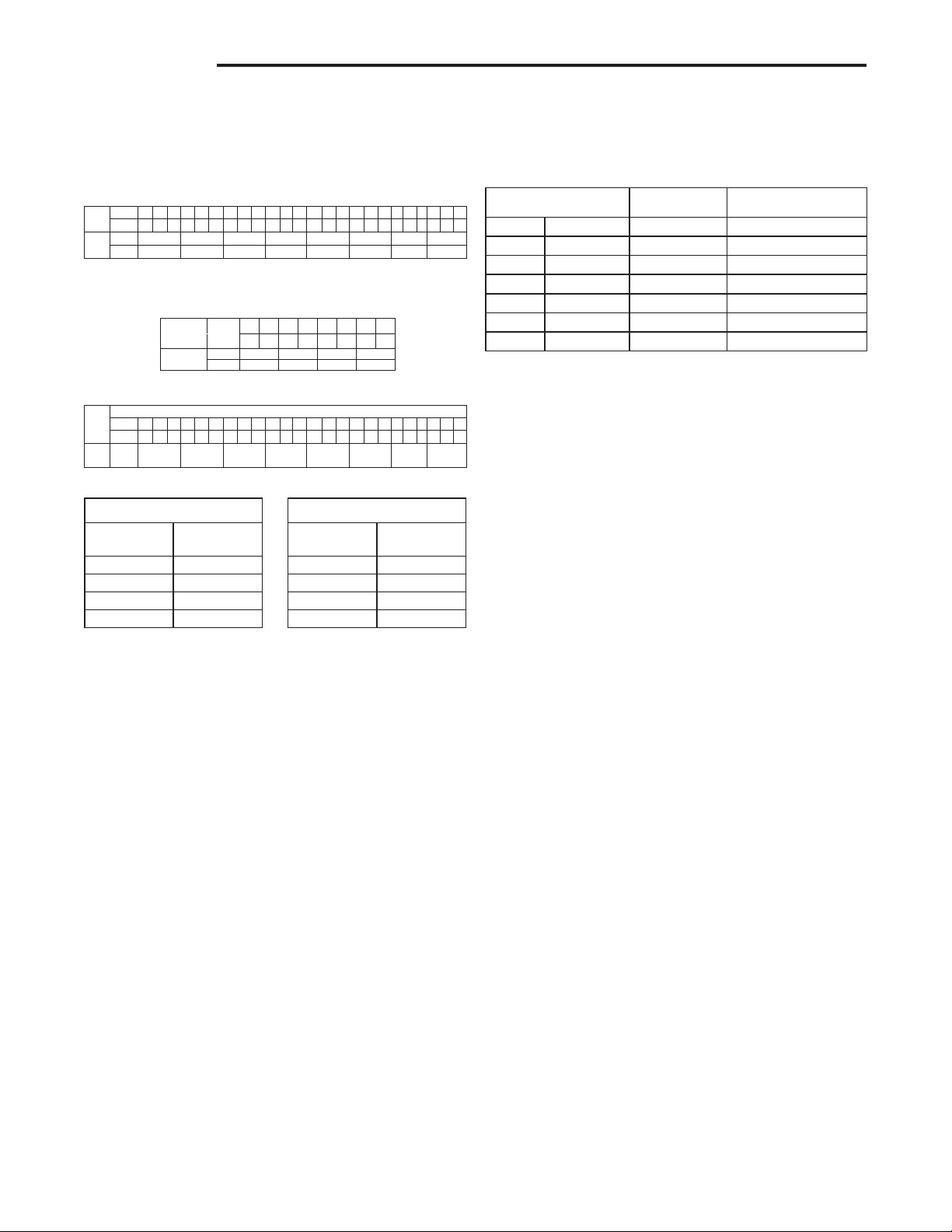
OPTION SWITCHES
Option switches on the 50M58-707 control are used to determine
the length of the delay-to-fan-off periods.The following tables show
the time periods that will result from the various switch positions.
HEAT OFF DELAY
DIP SW S3-3
S3-4
NOMINAL
(SECONDS)
OFF-OFF 90
OFF-ON 120
*ON-*OFF 150
ON-ON 180
W2 DELAY
DIP SW S3-1
S3-2
NOMINAL
(MINUTES)
*OFF-*OFF TWO STAGE
ON-OFF 10
OFF-ON AUTO
ON-ON 20
Average Calculated
Duty Cycle %
Low to High
Stage Delay
Demand
Equals or less than
0 38 12 minutes Light
38 50 10 minutes Light to Average
50 62 7 minutes Average
62 75 5 minutes Average to Heavy
75 88 3 minutes Heavy Light
88 100 1 minute Heavy
HEAT MODE
In a typical system, a call for first stage heat is initiated by closing
the W1 thermostat contacts. The inducer blower is energized
at high speed and the control waits for the low pressure switch
contacts to close. The humidifier (optional) is also energized at
this time. Once the low pressure switch contacts close, a pre-
purge is initiated. Then the inducer changes to low speed and
the 120V ignitor is powered.
At the end of the ignitor warm-up time, the first stage of the two
stage manifold gas valve is energized (low fire). Once flame
is detected, the HEAT delay-to-fan-on period begins. After the
delay-to-fan-on period ends, the 50M58-707 control will energize
the circulator fan at low heat speed. The electronic air cleaner
(optional) will also energize at this time.
For a two-stage thermostat, a call for second stage heat (W1
and W2) after a call for first stage heat will energize the inducer
at high speed and the circulator at high heat speed.The second
stage pressure switch contacts will close and energize the second
stage gas valve (high fire).
For a single-stage thermostat, when a call for heat occurs
(W1), a 10, 20 minute or auto mode heat staging timer will be
activated (timing is selectable with option switches S1-1 and
S1-2 positions). Following this delay, the second stage heat is
energized as above.
TheAUTO model algorithm is a method of energizing the second
stage gas valve based on the recent average of the heating duty
cycle. During a typical heating day, the low to high stage delay
is determined by using the average calculated duty cycle from
the table below.
OPERATION OPERATION
Cool Motor SPEED DIP SWITCH SETTING (S1-1, S1-2, S1-3)
*1 2 3 1 2 3 1 2 3 1 2 3 1 2 3 1 2 3 1 2 3 1 2 3
Position OFF OFF OFF ON OFF OFF ON ON OFF OFF ON OFF OFF OFF ON OFF ON ON ON OFF ON ON ON ON
Motor
SPEED
Cool
Ylo T4(60Hz) T3 T3 T4(60Hz) T4(60Hz) T3 T2 T2
YT4(120 Hz) T4(60Hz) T4(120Hz) T1 T2 T1 T4(120Hz) T3
*Factory default setting
Fan Motor SPEED DIP SWITCH SETTING (S2-2, S2-3, S2-4)
DIP SWITCH S2 SETTING
*2 3 4 2 3 4 2 3 4 2 3 4 2 3 4 2 3 4 2 3 4 2 3 4
Position OFF OFF OFF ON OFF OFF ON ON OFF OFF ON OFF OFF OFF ON OFF ON ON ON OFF ON ON ON ON
Motor
SPEED
Fan
GT1 T2 T3 T4(60Hz) T4(120Hz) T1 T1 T1
*Factory default setting
Heat Motor SPEED DIP SWITCH SETTING
(S1-4, S2-1)
*4 1 4 1 4 1 4 1
Position OFF OFF ON OFF ON ON OFF ON
Motor SPEED
Heat
W1 T1 T3 T3 T4(60Hz)
W2 T2 T2 T4(60Hz) T4(120Hz)
*Factory default setting