OPERATION
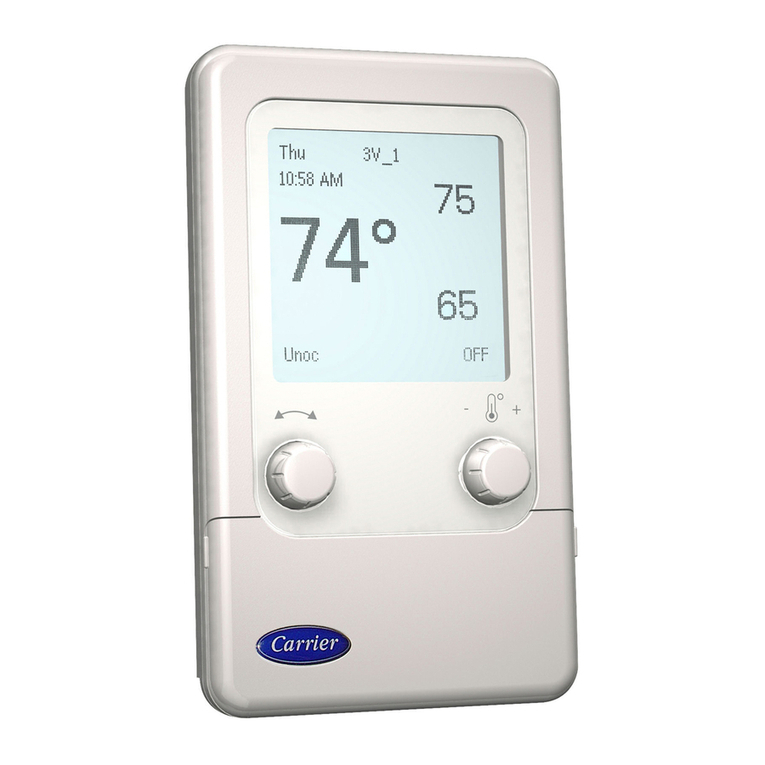
There are 3 system switches which are used to control op-
eration at the thermostat: Heat, Cool, and Fan. The Heat and
Cool switches can be set to either AUTO or OFF. The Fan
switch can be set to either AUTO or ON. When the fan is
running, the FAN indicator will be shown on the thermostat
display screen. When cooling mode is energized, the COOL
indicator will be shown on the thermostat display screen. When
heating mode is energized, the HEAT indicator will be shown
on the thermostat display screen. When the second stage of
heating or cooling is energized, a decimal point is displayed
between the heating and cooling set points.
AUTO Fan Mode — The fan will energize any time the
system energizes heating or cooling. The only exception is
when the thermostat controls a gas heating rooftop unit. The
thermostat will allow the rooftop unit to control the fan dur-
ing heating mode. The fan will run in cooling mode.
ON Fan Mode — The fan will operate continuously dur-
ing the occupied mode. In unoccupied mode the fan will only
operate when a system mode is energized.
AUTO Heating Mode — When the Heat switch is set
to AUTO, the Apollo control will energize heating when the
heating demand is 1.5° F or greater. The second stage of heat-
ing will energize when the demand becomes 2.0° F or greater.
OFF Heating Mode — When the Heat switch is set to
OFF, the Apollo control will not allow the rooftop unit to
energize heating.
AUTO Cooling Mode — When the Cool switch is set
to AUTO, theApollo control will energize cooling when the
cooling demand is 1.5° F or greater. The second stage of
cooling will energize when the demand becomes 2.0° F or
greater.
OFF Cooling Mode — When the Cool switch is set to
OFF, the Apollo control will not allow the rooftop unit to
energize cooling.
Temperature Trend Staging — When the Tempera-
ture Trend Staging option has been configured at the ther-
mostat, the thermostat tracks the temperatures at regular in-
tervals in each cooling or heating mode.As long as the space
temperature is improving, the Apollo control will not allow
the second stage to be energized. If the space temperature
stays the same or the demand becomes greater, the second
stage will energize.
Energy Saver Delay — When the thermostat enters a
cooling or heating mode and it detects a demand of 8° F or
greater, it will hold off energizing the second stage for
21 minutes. This will allow the first stage time to satisfy the
space demand.
Heating Lockout — When the heating lockout tem-
perature set point has been configured, and the Heating Lock-
out option has been configured to ON, the Apollo control
will not allow heating to energize when the outside air tem-
perature rises above the heating lockout set point.
Cooling Lockout — When the cooling lockout tem-
perature set point has been configured, and the Cooling Lock-
out option has been configured to ON, the Apollo control
will not allow cooling to energize when the outside air tem-
perature drops below the cooling lockout set point.
Time Delay Relay — The thermostat and the Apollo
control utilize a 5-minute time delay between the different
modes of operation for the rooftop unit. When a mode of
operation is deenergized, another mode cannot begin for
5 minutes.
TROUBLESHOOTING
SeeFig.7-11forfactory-wiring and Apollo control wir-
ing schematics.
Blank Display or Blinking Display at the
Thermostat
1. Check to ensure there is at least 20.5 VAC across the
2 terminals labelled 24 VAC.
2. If there is not at least 20.5 VAC, check the unit trans-
former which is powering the Apollo control.
3. If anAC voltage between 20.5 and 30 VAC is read, check
for 10 VDC between the terminal labelledWHTand RED.
If there is 0 VDC between the terminals, replace the Apollo
control.
4. If a value between 1 and 10 VDC is read, check the wir-
ing between the thermostat and the Apollo control.
5. If the thermostat display is blinking on and off, this is an
indication that there is a communication problem be-
tween the thermostat and the Apollo control. The ther-
mostat and the Apollo control communicate on the blue
and yellow wires. If either one is shorted, open, or crossed,
it will cause the thermostat display to blink.
NOTE: To check the wiring between the thermostat and the
Apollo control, do the following:
1. Remove the thermostat and connector board.
2. Wire the connector board to the Apollo control with a
short piece of 5-conductor cable.
3. Plug the thermostat into the connector board.
a. If thermostat powers up there is a wiring problem. Find
the open or shorted wire or replace the wiring between
the thermostat and the Apollo control.
b. If the thermostat does not power up, try another ther-
mostat. If the new thermostat will not power up, re-
place the Apollo control. If the new thermostat will
power up, replace the old thermostat.
The Control Will Not Energize Heating
1. The thermostat is not displaying the heat annunciator.
a. Check the heating lockout temperature set point and
options to make sure the outside air temperature is not
locking out heating mode.
b. Ensure that a sensor in the system is not reading above
the heating high limit temperature. If a supply air sen-
sor or a DX coil sensor is not connected to the Apollo
control, turn off the High Low Limits option at the
thermostat.
c. Check the Heat switch and make sure it is in the AUTO
position.
2. The thermostat is displaying the heat annunciator.
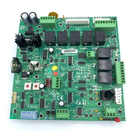
a. Check to see if the H1 LED is lit on the Apollo con-
trol. If it is not, replace the Apollo control. If the H1
LED is lit on the Apollo control, check the voltage
across the H1 relays contact. If it reads 24 VAC, re-
place the Apollo control. If it reads 0 to 2 VAC, check
the H1 contactor and the unit transformer.
4
