Cooper Crouse-Hinds GmbH 33
33
3
Explosionsgeschützte Klemmenkästen
Edelstahl GHG 725
2 Sicherheitshinweise
Die Edelstahlklemmenkästen sind
nicht für Zone 0 und Zone 20
geeignet.
Die auf den Klemmenkästen
angegebene Temperaturklasse und
Explosionsgruppe ist zu beachten.
Der Klemmenkästen sind von einer
Elektrofachkraft anzuschließen.
Das Betriebsmittel darf nicht bei Staubab-
lagerungen > 50mm Dicke, gem. EN 50 281-1-1,
betrieben werden.
Vor Inbetriebnahme müssen die Klemmen-
kästen entsprechend der im Abschnitt 6
genannten Anweisung geprüft werden.
Alle Fremdkörper müssen vor der ersten
Inbetriebnahme aus den Klemmenkästen
entfernt werden.
Beachten Sie die nationalen Sicherheits-
und Unfallverhütungsvorschriften und die
nachfolgenden Sicherheitshinweise in
dieser Betriebsanleitung, die wie dieser
Text in Kursivschrift gefasst sind!
3 Normenkonformität
Die Klemmenkästen entsprechen den
Anforderungen der EN 50014, EN 50019, EN
50 020 und EN 50 281-1-1 (vergleichbare
internationale Standards IEC 60079-0,
IEC 60079-7, IEC 60079 -11).
94/9 EG: Geräte und Schutzsysteme zur
bestimmungsgemäßen Verwendung in
explosionsgefährdeten Bereichen.
Weitere Anforderungen wie die EG-Richtlinie
"Elektromagnetische Verträglichkeit" (89/336/
EWG) werden von den Klemmenkästen
erfüllt. Sie wurden entsprechend dem Stand
der Technik und gemäß BS EN ISO 9001
entwickelt, gefertigt und geprüft.
4 Verwendungsbereich
Die Edelstahlklemmenkästen sind zum
Einsatz in explosionsgefährdeten Bereichen
der Zonen 1 und 2 sowie der Zonen 21 und
22 gemäß IEC 60079-14 und IEC 60079-10
geeignet!
Die eingesetzten Gehäusematerialien
einschließlich der außenliegenden Metallteile
bestehen aus hochwertigen Werkstoffen, die
einen anwendungsgerechten Korrosions-
schutz und Chemikalienresistenz in "normaler
Industrieatmosphäre" gewährleisten:
- Edelstahl
- Polymer CR (Dichtung)
- Silikon (Dichtung)
- PUR (Dichtung)
Bei einem Einsatz in extrem aggressiver
Atmosphäre sind die zusätzlichen Informatio-
nen über die Chemikalienbeständigkeit der
eingesetzten Kunststoffe bei der Cooper
Crouse-Hinds Niederlassung zu erfragen.
5 Verwendung / Eigenschaften
Die Klemmenkästen dienen zum Verteilen von
elektrischer Energie z.B. Lichtstromkreise ,
Heizstromkreise, Steuerstromkreise, eigen-
sichere Stromkreise usw. (Temperaturklasse,
Explosionsgruppe, zulässige Umgebungs-
temperatur - siehe technische Daten).
Die für die "Eigensicherheit" maßgeben-
den elektrischen Grenzwerte sind zu
beachten.
Die Klemmenkästen sind auch im "normalen
Industriebereich" verwendbar.
Angaben aus Punkt 3 und 4 sind bei der
Verwendung zu berücksichtigen.
Andere als die beschriebenen Anwendun-
gen sind ohne schriftliche Erklärung der
Fa. COOPER CROUSE-HINDS nicht
zulässig.
Beim Betrieb sind die in der Betriebsanlei-
tung unter Punkt 7 genannten Anweisun-
gen zu beachten.
Die Verantwortung hinsichtlich Eignung
und bestimmungsgemäßer Verwendung
dieser Klemmenkästen liegt allein beim
Betreiber.
6 Installation
Für das Errichten / Betreiben sind die
relevanten nationalen Vorschriften, sowie die
allgemein anerkannten Regeln der Technik
maßgebend.
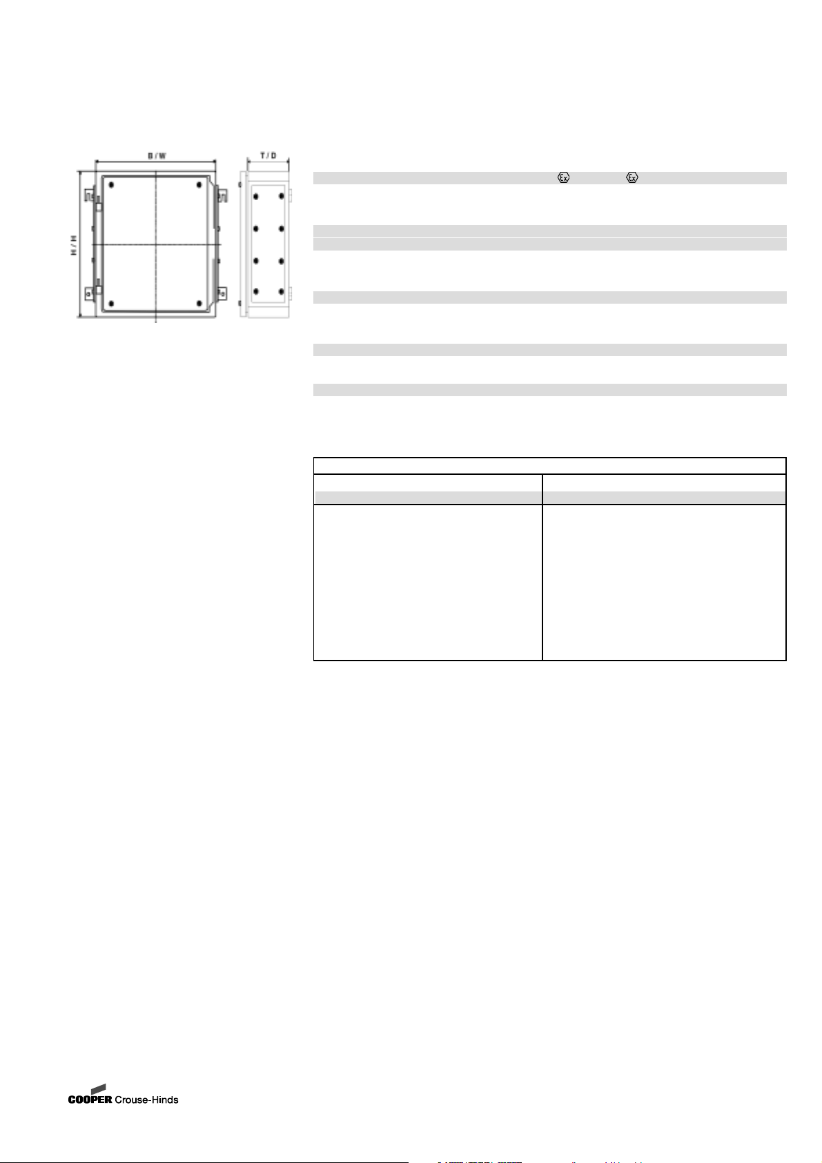
6.1 Montage
Die Montage der Edelstahlklemmenkästen
kann ohne Öffnen der Gehäuse erfolgen.
Die Klemmenkästen dürfen bei der Direkt-
montage an der Wand nur an den vorgese-
henen Befestigungspunkten eben aufliegen.
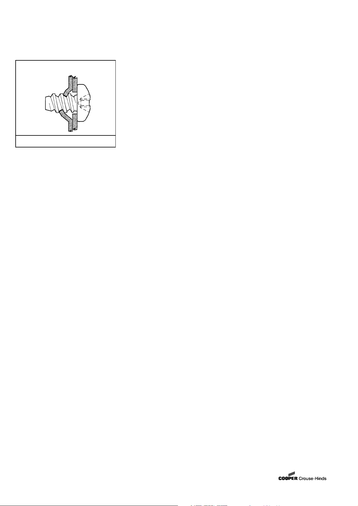
Die gewählte Schraube muss der
Befestigungsöffnung angepasst sein. Zum
befestigen der Klemmenkästen verwenden
Sie alle Befestigungslaschen.
6.2 Öffnen des Gerätes /
Elektrischer Anschluss
Vor Öffnen der Geräte ist die Spannungs-
freiheit sicherzustellen bzw. sind geeigne-
te Schutzmaßnahmen zu ergreifen.
Der elektrische Anschluss des Betriebs-
mittels darf nur durch Elektrofach-
personal erfolgen in Anlehnung an
EN 60079-14.
Die im Deckel der Klemmenkästen
angegebene Strombelastungstabelle muß
beachtet werden.
Um eine unzulässige Erwärmung zu
vermeiden ist die maximale Klemmen-
bestückung sowie der maximale
Bemessungsstrom zu beachten.
Die Isolation der Anschlussleitungen
muss bis an die Klemme heranreichen.
Der Leiter selbst darf nicht beschädigt
sein.
Bei der Verwendung von mehr- oder
feindrähtigen Anschlusskabel und An-
schlussleitungen sind die Aderenden
entsprechend den geltenden nationalen und
internationalen Vorschriften zu behandeln
(z.B. Verwendung von Aderendhülsen).
Die minimal und maximal anschließbaren
Leiterquerschnitte sind zu beachten.
Alle Schrauben und/oder Muttern der Anschluss-
klemmen, auch die der nicht benutzten, sind fest
anzuziehen.
Die eingebaute Standardklemme ist zum
Direktanschluss von Leitern mit Kupferadern
ausgelegt.
Zur Aufrechterhaltung der Zündschutzart
ist der Leiteranschluss mit besonderer
Sorgfalt durchzuführen.
Für den Anschluss von eingebauten Bolzen-
klemmen sind DIN-Kabelschuhe zu verwenden.
Achtung: Das Aufpressen der Kabelschu-
he auf das Kabel ist fachgemäß durchzu-
führen. Es ist sicherzustellen, dass die
erforderlichen Mindestluftstrecken
eingehalten werden (bei 690V >12mm).
Bei Mischbestückungen Ex - e / Ex - i sind
die erforderlichen Mindestabstände
einzuhalten (siehe z.B. EN 50020 ).
Bei geöffneten Geräten ist sicherzustellen
(Spannungsfreiheit herstellen), dass keine
Spannungsverschleppung auf die
angeschlossenen eigensicheren Strom-
kreise übergreift.
Die Errichtungshinweise für eigensichere
elektrische Betriebsmittel sind zu beachten.
Es ist sicherzustellen, dass die für den
speziellen, eigensicheren Stromkreis zulässige
äußere Kapazität und Induktivität nicht über-
schritten wird.
6.2.1 Leerkästen mit U-Bescheinigung
In die Leerkästen mit U-Bescheinigung
dürfen für den Einbau in Ex-e Gehäuse
bescheinigte Komponenten eingebaut
werden. Die max. angegebene Verlustleitung,