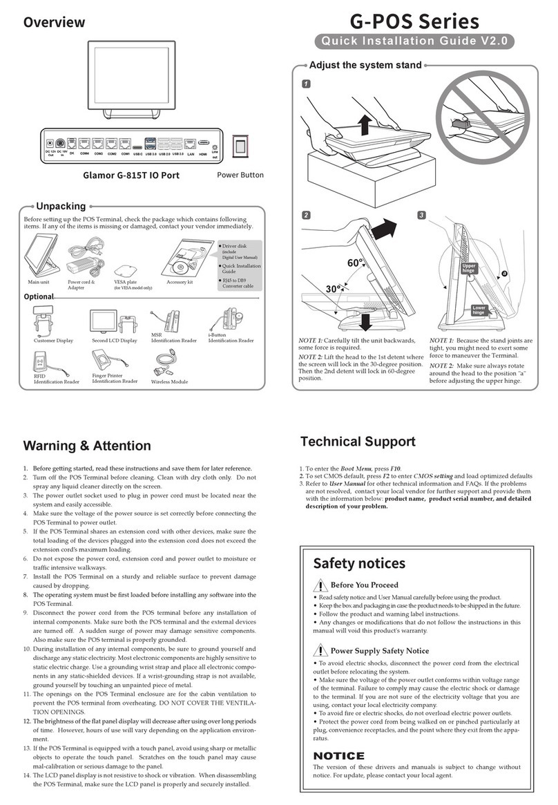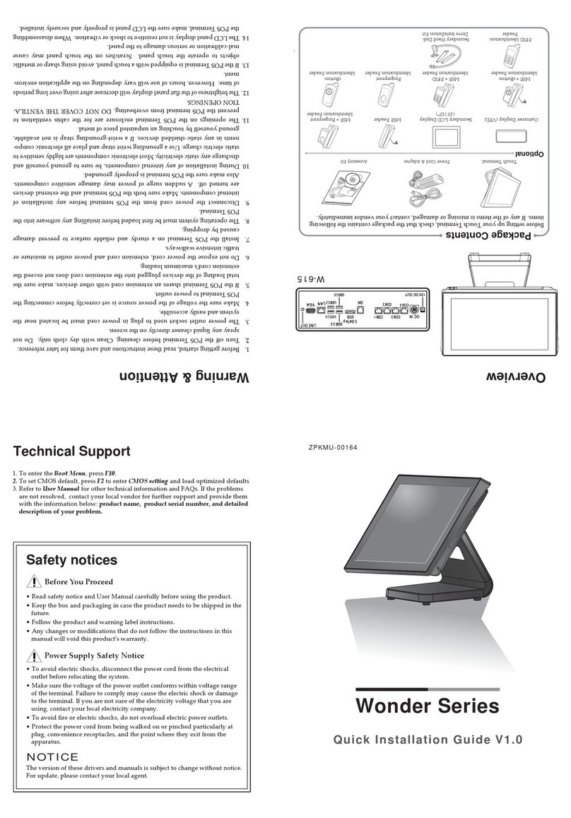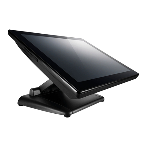
Adjust the system stand
NOTE 1: Carefully tilt the unit backwards,
some force is required.
NOTE 2: Li the head to the 1st detent where
the screen will lock in the 30-degree position.
Then the 2nd detent will lock in 60-degree
position.
NOTE 3: Because the stand joints are
tight, you might need to exert some
force to maneuver the Terminal.
NOTE 4: Make sure always rotate
around the head to the position "a"
before adjusting the upper hinge.
30°
60°
Lower
hinge
Upper
hinge
Extend the kickstand and place the Touch Terminal on
the stable surface.
Installing the VESA Mount (Optional)
1. Remove the MSR (Magnetic
Stripe Reader) module
compartment cover. (a)
2. Firmly connect the MSR
connector into the slot inside
the compartment. (b)
3. Remove the two screws from
the compartment. (c)
4. Align and install the MSR
module onto its
compartment. (d)
5. Secure the MSR module to
the Touch Terminal with the
two screws. (e)
a
e
c
b
d
Installing the Customer Display (Optional)
1. Place the Touch Terminal on a so and flat surface, with the LCD panel facing
down. Then push the stand upwards to access the screws securing the stand to the
Touch Terminal. (a)
2. Remove the four screws securing the stand
to the Touch Terminal. (b)
3. Remove the stand. (c)
4. Remove the VESA compartment cover. (d)
5. Remove the I/O port cover. (e)
6. Detach the customer display compartment
cover from the customer display. (f)
7. Route the customer display cable through
the cable compartment on the stand. (g)
8. Install the stand (c) and secure the stand to
the Touch Terminal with the four screws (b).
9. Align and install the customer display into
its slot on the stand. (h)
10. Secure the customer display to the Touch
Terminal using the two screws. (i)
11. Align and install the customer display
compartment cover. (f)
12. Connect the customer display cable to one of
the COM ports on the Touch Terminal. (j)
NOTE: Pre-seing the output voltage of
COM port is needed. Please refer to the UM
on page 33/34.
13. Replace the I/O port cover.
a
f
b
j
i
d
c
e
h
g
FLEX Type
FLEX Type
FLEX Type
NANO Type
LITE Type
Installing the Secondary LCD Display (Optional)
1. Place the Touch Terminal on a so and flat surface, with the LCD panel facing
down. Then push the stand upwards to access the screws securing the stand to the
Touch Terminal. (a)
2. Remove the four screws securing the stand
to the Touch Terminal. (b)
3. Remove the stand. (c)
4. Remove the VESA compartment cover. (d)
5. Deaach the cable compartment cover from
the secondary LCD display. (e)
6. Route the secondary LCD display USB
Y-cable through the cable guides on the
stand as illustrated. (f)
7. Install the stand (c) and secure the stand to
the Touch Terminal with the four screws (b).
8. Align and install the secondary LCD display
into its slot on the stand. (g)
9. Secure the secondary LCD display to the
Touch Terminal with the two screws. (h)
10. Align and install the cable compartment
cover. (e)
11. Connect the secondary LCD display
USB Y-cable to the USB ports on Touch
Terminal. (i)
a
f
b
i
d
c
e
h
g
a
Installing the Customer Display (Optional)
1. Align and install the mount bracket on
the back of the Touch Terminal. (a)
2. Secure the mount bracket to the Touch
Terminal with the four screws. (b)
3. Drill four small holes on the mounting
location and insert the plastic washers
into the holes. (c)
4. Align by the screw holes and then
install the wall bracket on the wall. (d)
5. Secure the wall bracket to the wall
with the four supplied screws. (e)
6. Align and hook the Touch Terminal to
the wall bracket, and then push down
to secure it into place. (f)
1. Place the Touch Terminal on a so and
flat surface, with the LCD panel facing
down.
2. Remove the four screws securing the
stand to the Touch Terminal. (a)
3. Remove the stand. (b)
4. Detach the I/O port cover. (c)
5. Align and place the customer display
on the rear of the Touch Terminal. (d)
6. Place the stand on the top of the
customer display bracket. (b)
7. Route the customer display cable as
shown in the illustration. (e)
8. Connect the customer display cable to
one of the COM ports on the Touch
Terminal. (f)
NOTE: Pre-seing the output voltage of
COM port is needed. Please refer to the
UM on page 33/34.
9. Replace the I/O port cover.
10. Secure the stand and customer display
bracket to the Touch Terminal with the
four screws. (a)
1. Place the Touch Terminal on a so and flat surface, with the LCD panel facing down.
Then push the stand upwards (a) for easy access to the cable compartment cover.
2. Remove the cable compartment cover (b).
3. Route the power adapter and the network cable through the cable compartment. (c)
4. Connect the network cable to the LAN port. Then connect the power adapter to the
DC IN jack. (d)
5. Use the cable clip to secure the power adapter in place. (e)
6. Align and install the cable compartment cover. (b)
Installing the Power Cord, Power Adapter,
and Network Cable
7. Connect the power adapter to the
power cord. Then plug the other
end of the power cord to an
electrical outlet. (f)
8. Connect the network cable to
connect to a hub or switch. (f)
d
e
f
a
b
c
Installing the Identification Reader (Optional)
a
b
d
e
f
c
a
b
de
f
c
90° (max.)


