manuals.online logo
Brands
  1. Home
  2. •
  3. Brands
  4. •
  5. Cooper Lighting Solutions
  6. •
  7. Lighting Equipment
  8. •
  9. Cooper Lighting Solutions Sure-Lites User manual

Cooper Lighting Solutions Sure-Lites User manual

Questions? 1-800-334-6871 [email protected]
1
Instruction Manual / Manuel d’instructions/ Instrucciones
FEATURES
This emergency battery pack (EBP) includes extra features which enhance its
operation and maintainability.
1. Patented EZ key battery disconnect: When the EZ key is inserted into the test button,
the battery is disconnected. This feature prevents unnecessary cycling of the battery
during the construction process. It can also be used if the room is decommissioned
for an extended period to prevent the batteries from being over discharged.
2. Patent pending Test Button / Indicator Light / Laser Input: The test button
houses the EZ key, powers the indicator light, contains the laser input for testing
and functions as the mechanical test button. Integration of these functions
improves performance and xture aesthetics.
3. Power controlled output: This feature maintains consistent light output during
the entire 90 minutes of emergency operation ensuring there is no drop in lumen
output as the battery voltage drops
4. Self Diagnostics Testing: The unit will perform a battery capacity, lamp/LED, and
charge circuit test every 30 days for 30 seconds. During this time, the indicator
LED will change to a steady yellow. It will perform a full battery capacity (90
minute) test once per year. During this time, the indicator LED will change to a
blinking yellow.
Field Installation Classication
1. Determine electrical compatibility with xture: Verify the emergency driver wattage
(14 watts) does not exceed the driver’s AC input. Also, verify that the forward voltage
of the LEDs is within the operating parameters of the selected model (see table
below).
2. Calculate Lumen output during emergency operation: Go to the website www.
designlights.org and identify the light xture by using the available search criteria.
Determine the xture rated data – ecacy in lumens/watt. Multiply the xture ecacy
by the output wattage of the selected emergency battery pack to determine the lumen
output of the xture during emergency operation.
Example: Fixture ecacy = 100 lumens/watt
EBPLED14WSD provides 14 watts of constant power
Fixture output = 100 lumens/watt X 14 watts = 1400 lumens during
emergency operation
3. Insure means of egress lighting levels: Follow industry standard methods of
lighting layout to determine placement of emergency battery pack equipped xtures.
Verify the selected EBP will provide enough lumen output to meet path of egress
illumination requirements.
Important Safeguards
WHEN USING ELECTRICAL EQUIPMENT, BASIC SAFETY PRECAUTIONS SHOULD
ALWAYS BE OBSERVED INCLUDING THE FOLLOWING
1. READ AND FOLLOW ALL SAFETY INSTRUCTIONS
2. Do not use outdoors.
3. Do not mount near gas or electric heaters.
4. Equipment should be mounted in locations and at adequate heights to prevent
tampering by unauthorized personnel.
5. The use of accessory equipment not recommended by Cooper Lighting Solutions
may cause an unsafe condition and will void the warranty.
6. Do not use this equipment for other than its intended purpose.
7. Not for use with sealed and gasketed xtures.
8. SAVE THESE INSTRUCTIONS.
NOTES:
1. To prevent voltage from being present on the output wires (Red/White & Blue/White),
do not connect the test button assembly to the EBP or insure the EZ key is securely in
place.
2. This product is for use with LED xtures with loads capable of the output wattage and
forward voltage within the ranges below
3. Make sure all the connections are in accordance with the National Electrical Code
and any local regulations.
4. To reduce the risk of electrical shock, disconnect both normal and emergency
power supplies, including the test button indicator light (which disconnects the
battery) before servicing. Ensuring the battery disconnect (EZ Key) is securely in
place also prevents battery powered operation.
5. These emergency battery packs can be eld, or factory installed depending on
version. See mounting section for details.
6. This product is for use in indoor xtures only. Do NOT use near heated air
handling outlets, wet locations or hazardous locations.
7. An un-switched AC power source is required. (120 - 277 volts 50/60 HZ) for
proper operation.
8. The sealed, no-maintenance battery is eld replaceable. Contact the
manufacturer for information on replacement if needed.
9. All maintenance should be performed by qualied service personnel.
ENGLISH
EBPLEDSD14W
Risk of Fire/Electric Shock
If not qualied, consult an electrician.
Output Power (W) MinVf (V) Max Vf (V)
14W Versions 14 16 55
Output Power (W) MinVf (V) Max Vf (V)
14W Versions 14 16 55
Risk of Electric Shock
Disconnect power at fuse or circuit breaker before installing or servicing
Instructions for Surelites LED Emergency Battery Packs
Sure-Lites
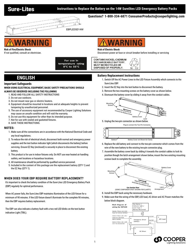
2
INSTALLATION
1. Mounting The EBP can be mounted inside a xture channel, on the back of a xture,
or near the xture. The ex conduit should be connected to a junction enclosure
which allows access to the wiring connections for grounding.
(Note: EBP assemblies without conduit must be factory installed in the wireway of the
xture).
2. Wiring Refer to the block diagram below for the wiring of the LED load, AC driver, and
AC power. The unswitched AC power for the EBP and the power for the AC driver
should be from the same branch circuit to prevent disconnecting two (2) sources of
power and the battery during servicing.
3. Mounting the Test Button / Indicator Light / Laser Input Mount the Test Button
/ Indicator Light / Laser Input so the indicator light is visible once the xture is
installed. Proper mounting is required for accessibility and functionality of the laser
input testing feature and EZ key battery disconnect.ount
OPERATION
Once AC power is permanently applied to the blue wire of the xture, remove the EZ key and
store it if desired for later use. The Sure-Lites Eagle Eye Self Diagnostics is continuously
monitoring your emergency xture and will signal any failure through the 3-color indicator
LED.
SELF DIAGNOSTICS TESTING
The unit will perform a battery capacity, lamp/LED, and charge circuit test every 30 days for
30 seconds. During this time, the indicator LED will change to a steady yellow. It will perform
a full battery capacity (90 minute) test once per year. During this time, the indicator LED will
change to a blinking yellow.
MANUAL TESTING
• 10 Second “Installation” test – Press and release the test button once during fast
charge (blinking green) to initiate a 10 second quick test. The sign will switch to
emergency mode for 10 seconds allowing the installer to verify proper installation
of the unit, and the LED indicator will turn solid yellow.
• 30 Second Test - Press and release the test button once during oat charge
(steady green). The indicator LED will turn steady yellow to indicate the unit is
performing a 30 second test of the batteries and lamps/ LEDs.
• 90 Minute Test - Press and release the test button a second time during a 30
second test (steady yellow) to change to a 90-minute test. During this test, the
LED indicator will change to blinking yellow, and the circuit will perform a full
battery capacity, charge circuit, and LED test.
• Canceling Test – Press and release the test button during the 90-minute test
(ashing yellow) to return the xture to its original state (fast charge or oat
charge).
CLEARING FAILURE CODES
• A battery failure (LED two blink red) can be cleared by replacing the battery.
Disconnecting the battery and AC power, or performing a full 90-minute discharge, will
reset the error code, however, it will return if the battery is faulty.
• Charge Circuit (LED three blink red) and lamp/LED failure (LED four blink red) will
clear when the unit successfully passes a manual or automatic 30 second test.
INDICATORS
• LED Off - No power to unit, emergency mode.
• LED Steady Green - Unit is fully charged and is oat charging the battery to maintain
readiness.
• LED Green Pulse - Unit is in a 24-hour fast charge of the battery.
• LED Two Blink Red - Battery has failed a capacity test, or the battery is disconnected.
See “Clearing Failure Codes” above.
• LED Three Blink Red - Battery charge circuit has failed. See “Clearing Failure Codes”
above.
• LED Four Blink Red - Lamps have burned out, or on an EXIT/Combo, 10% or more of
the LEDs have failed. See “Clearing Failure Codes” above.
• LED Steady Yellow - 30 second test or 10 second quick test (Fast Charge only).
• LED Blinking Yellow - 90-minute test.
5-YEAR LIMITED WARRANTY
THE FOLLOWING WARRANTY IS EXCLUSIVE AND IN LIEU OF ALL OTHER WARRANTIES,
WHETHER EXPRESS, IMPLIED OR STATUTORY INCLUDING, BUT NOT LIMITED TO, ANY
WARRANTY OF MERCHANTABILITY OR FITNESS FOR ANY PARTICULAR PURPOSE.
Cooper Lighting Solutions warrants to customers that, for a period of ve years from the date
of purchase, Cooper Lighting Solutions products will be free from defects in materials and
workmanship. The obligation of Cooper Lighting Solutions under this warranty is expressly
limited to the provision of replacement products. This
warranty is extended only to the original purchaser of the product. A purchaser’s receipt or
other proof of date of original purchase acceptable to Cooper Lighting Solutions. This is re-
quired before warranty performance shall be rendered. This warranty does not apply to Coo-
per Lighting Solutions products that have been altered or repaired that have been subjected
to neglect, abuse, misuse or accident (including shipping damages). This warranty does not
apply to products not manufactured by Cooper Lighting Solutions which have been supplied,
installed, and/or used in conjunction with Cooper Lighting Solutions products. Damage to the
product caused by replacement bulbs or corrosion or discoloration of brass components are
not covered by this warranty.
LIMITATION OF LIABILITY:
IN NO EVENT SHALL COOPER LIGHTING SOLUTIONS BE LIABLE FOR SPECIAL, INDIRECT,
INCIDENTAL, OR CONSEQUENTIAL DAMAGES (REGARDLESS OF THE FORM OF ACTION,
WHETHER IN CONTRACT, STRICT LIABILITY, OR IN TORT INCLUDING NEGLIGENCE), NOR
FOR LOST PROFITS; NOR SHALL THE LIABILITY OF COOPER LIGHTING SOLUTIONS FOR ANY
CLAIMS OR DAMAGE ARISING OUT OF OR CONNECTED WITH THESE TERMS OR THE MANU-
FACTURE, SALE, DELIVERY, USE, MAINTENANCE, REPAIR OR MODIFICATION OF COOPER
LIGHTING SOLUTIONS PRODUCTS, OR SUPPLY OF ANY REPLACEMENT PARTS THEREFORE,
EXCEED THE PURCHASE PRICE OF COOPER LIGHTING SOLUTION PRODUCTS GIVING RISE
TO A CLAIM. NO LABOR CHARGES WILL BE ACCEPTED TO REMOVE OR INSTALL FIXTURES.
To obtain warranty service, please contact Cooper Lighting Solutions, at 1-800-334-6871,
press option 2 for Customer Service, or via e-mail [email protected]
and include the following information:
• Name, address and telephone number
• Date and place of purchase
• Catalog and quantity purchase
• Detailed description of problem
All returned products must be accompanied by a Return Goods Authorization Number issued
by the Company and must be returned freight prepaid. Any product received without a Return
Goods Authorization Number from the Company will be refused. Cooper Lighting Solutions is
not responsible for merchandise damaged in transit. Repaired or replaced products shall be
subject to the terms of this warranty and are inspected when packed. Evident or concealed
damage that is made in transit should be reported at once to the carrier making the delivery
and a claim led with them.
Reproductions of this document without prior written approval of Cooper Lighting Solutions are strictly prohibited.
For assistance, call 1-800-334-6871 or e-mail us at [email protected]
Printed in China
MAINTENANCE
None required. Replace the batteries as needed according to ambient conditions. Equipment
should be tested every 30 days in accordance with local codes.
Refer any service requirements indicated by these checks to qualied personnel.
TROUBLESHOOTING GUIDE
If LED heads or charge indicator LED does not illuminate, check the following:
1. Check AC supply – verify that unit has 24-hour AC supply.
2. Unit is shorted or battery is not connected.
3. Battery discharged. Permit unit to charge for 24-hours and then re-test.
4. If following the above trouble shooting hints does not solve your problem, contact
your local Cooper Lighting Solutions representative for assistance
Lighting Solutions
1121 Highway 74 South, Peachtree City, GA 30269
www.cooperlighting.com
© 2022 Cooper Lighting Solutions March 7, 2022 11:46 AM
IB518601ML
OFF - EMERGENCY
MODE / POWER OFF
2 BLINK RED -
BATTERY FAILURE
STEADY GREEN -
FULL / FLOAT
CHARGE
STEADY BLINK YELLOW
- 90 MINUTE TEST
3 BLINK RED - CHARGE
CIRCUIT FAILURE
4 BLINK RED - LAMP/
LED FAILURE
STEADY YELLOW -
QUICK TEST
STEADY BLINK
GREEN - FAST
CHARGE
SURE-LITES
SELF
DIAGNOSTICS
120-277 VAC Neutral WHT

This manual suits for next models

1

Other Cooper Lighting Solutions Lighting Equipment manuals

Cooper Lighting Solutions Lumark Axcent Small User manual

Cooper Lighting Solutions

Cooper Lighting Solutions Lumark Axcent Small User manual

Cooper Lighting Solutions ASWP User manual

Cooper Lighting Solutions

Cooper Lighting Solutions ASWP User manual

Cooper Lighting Solutions Fail-Safe FCC User manual

Cooper Lighting Solutions

Cooper Lighting Solutions Fail-Safe FCC User manual

Cooper Lighting Solutions HLBSL-4 Series User manual

Cooper Lighting Solutions

Cooper Lighting Solutions HLBSL-4 Series User manual

Cooper Lighting Solutions B Series User manual

Cooper Lighting Solutions

Cooper Lighting Solutions B Series User manual

Cooper Lighting Solutions ALL-PRO MS185 User manual

Cooper Lighting Solutions

Cooper Lighting Solutions ALL-PRO MS185 User manual

Cooper Lighting Solutions Halo LCR2 User manual

Cooper Lighting Solutions

Cooper Lighting Solutions Halo LCR2 User manual

Cooper Lighting Solutions Sure-Lites User manual

Cooper Lighting Solutions

Cooper Lighting Solutions Sure-Lites User manual

Cooper Lighting Solutions Halo H350FR2ICAT User manual

Cooper Lighting Solutions

Cooper Lighting Solutions Halo H350FR2ICAT User manual

Cooper Lighting Solutions ephesus LUMAVISION User manual

Cooper Lighting Solutions

Cooper Lighting Solutions ephesus LUMAVISION User manual

Cooper Lighting Solutions Might-D-Light LED140 User manual

Cooper Lighting Solutions

Cooper Lighting Solutions Might-D-Light LED140 User manual

Cooper Lighting Solutions Halo TGS2SCS2FRBLE40AB User manual

Cooper Lighting Solutions

Cooper Lighting Solutions Halo TGS2SCS2FRBLE40AB User manual

Cooper Lighting Solutions Halo AL6501LED User manual

Cooper Lighting Solutions

Cooper Lighting Solutions Halo AL6501LED User manual

Popular Lighting Equipment manuals by other brands

Sunoptic Technologies LLS-2000 Operator's manual

Sunoptic Technologies

Sunoptic Technologies LLS-2000 Operator's manual

American DJ LS-80 User instructions

American DJ

American DJ LS-80 User instructions

ADJ ULTRA GO PAR7X User instructions

ADJ

ADJ ULTRA GO PAR7X User instructions

Ayra ITA02 MKII user manual

Ayra

Ayra ITA02 MKII user manual

El-Björn FLEX LED strip manual

El-Björn

El-Björn FLEX LED strip manual

Color imagination MINISPOT 250 user manual

Color imagination

Color imagination MINISPOT 250 user manual

InterTest iShot UV/White LED Light Source Kit manual

InterTest

InterTest iShot UV/White LED Light Source Kit manual

Stellar Effects Modeling Solutions REFIT SIGNATURE Series manual

Stellar Effects Modeling Solutions

Stellar Effects Modeling Solutions REFIT SIGNATURE Series manual

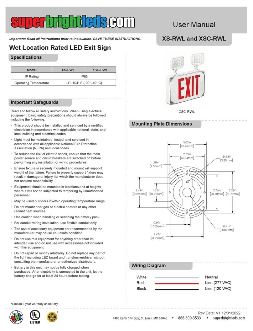
SBL XS-RWL user manual

SBL

SBL XS-RWL user manual

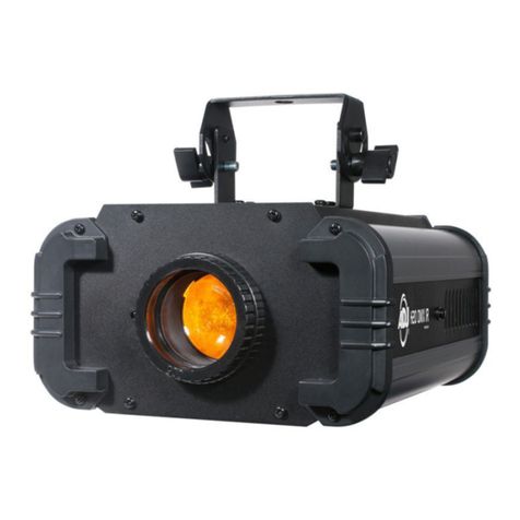
ADJ H2O DMX IR user manual

ADJ

ADJ H2O DMX IR user manual

dymax 38105 - 2000-EC Operation manual

dymax

dymax 38105 - 2000-EC Operation manual

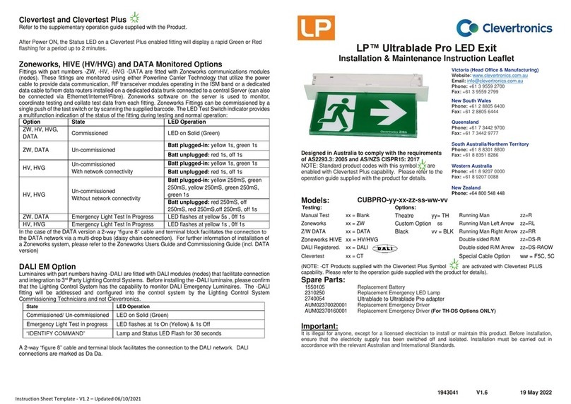
Clevertronics LP CUBPRO Series ASSEMBLY, INSTALLATION & MAINTENANCE INSTRUCTIONS

Clevertronics

Clevertronics LP CUBPRO Series ASSEMBLY, INSTALLATION & MAINTENANCE INSTRUCTIONS

PORTMAN P2 hexaline user manual

PORTMAN

PORTMAN P2 hexaline user manual

Werner Dosiertechnik POOLKLAR Touch XL manual

Werner Dosiertechnik

Werner Dosiertechnik POOLKLAR Touch XL manual

Paradise Datacom PH-6.5K-4 manual

Paradise Datacom

Paradise Datacom PH-6.5K-4 manual

ARANI CL12-24W-xxK-WH-V3 Installation sheet

ARANI

ARANI CL12-24W-xxK-WH-V3 Installation sheet

Ibiza LMH350LED user manual

Ibiza

Ibiza LMH350LED user manual

Beamz SparkleWall LED96 RGBW 3x2mtr instruction manual

Beamz

Beamz SparkleWall LED96 RGBW 3x2mtr instruction manual

manuals.online logo
manuals.online logoBrands
  • About & Mission
  • Contact us
  • Privacy Policy
  • Terms and Conditions

Copyright 2025 Manuals.Online. All Rights Reserved.