Stellar Effects Modeling Solutions REFIT SIGNATURE Series User manual

1
Stellar Effects Modeling Solutions Presents:
The REFIT SIGNATURE SERIES
Lighting Effects System
model by: Neil Smith used with permission

2
TABLE OF CONTENTS
3 –Introduction
4 –How To Use This Guide
5 –Getting Started
6 –Lighting Modifications
13 –Soldering Tips
18 –Board Layout and Overview
23 –The Stellar Effects Refit Signature Series Harness
24 –Upper Saucer Lighting Checklist and Diagram
26 –Lower Saucer Lighting Checklist and Diagram
28 –Saucer Harness Terminal Layout
30 –Secondary Hull/Neck Lighting Checklist and Diagram
31 –Nacelle Lighting Checklist and Diagram
33 –Interior LED Strip Lighting Placement
34 –Raytheon Lighting
36 –Remote Control Functions and Operations
41 –Using Subassemblies/Final Assembly Tips

3
INTRODUCTION
Welcome to Stellar Effects Modeling’s lighting kit harness for the Refit Signature
Series lighting effects board for the PL 1:350 scale USS Enterprise 1701 Refit Starship
model kit! In purchasing this kit and the effects board it is designed for, it can be
assumed you’re building a very serious model requiring countless hours of work and
planning and building and, most of all, FUN! And you’re likely looking for a very accurate
representation of the beautiful Enterprise as she appeared in the movies or, in some
cases, your own version of the Grand Lady! We’re here to help you in the process so you
can hopefully have less aggravation and more “WOW!” as you assemble this wonderful
model.
This model kit is one of the most challenging and involved kits a modeler can
face, especially when it comes to lighting, so make sure to follow all steps carefully and
test all connections as you go.
The manual that follows is designed to help you easily install and connect all the
lighting you need to make your model stand out. We’ve taken great consideration to
make this kit as simple to install as possible.. (Particularly if you’re modifying your build
for custom lighting options and effects) Basic soldering skills are assumed with this kit,
but if you need help or are not as experienced, feel free to contact us at Stellar Effects
and we’ll do our best to assist you! We are confident that anyone can learn the skills
necessary to make this lighting kit work for your build and we’ll help you in any way we
can!
This manual is intended to be a usable reference for how the lighting kit is
designed to work with the Refit Signature Series effects board. It is not the ONLY way to
do things and you, as the builder, are perfectly welcome to deviate and experiment with
your own version of lighting the Big E. (ONLY recommended for experienced builders)
However, we do caution against using other materials (such as LED’, wires, resistors,
power supplies, etc) not included with or recommended for this kit as you may damage
the lights you’re using or, worse, the board itself. Stellar Effects Modeling Solutions
claims NO RESPONSIBILITY for any damage caused by incorrectly using the supplied
products or any damage caused by using materials other than those included in this kit.
*Note: using materials or components other than those included in this kit may void
your warranty on your Refit Signature Series or other product!

4
HOW TO USE THIS GUIDE
This guide is presented in a format intended to be easy to decipher for the
intermediate to advanced model builder who is passably familiar, at least, with lighting
diagrams and electrical current flow. For the beginner, this kit is certainly usable! But
you might want to take some time to gather some information and familiarize yourself
with basic terminology and knowledge on electrical diagrams and current. This is
especially true if you intend to deviate at all from the instructions for this kit.
The guide is presented in an “easy-to-read” format where the builder can simply
take the string of lights, as marked, and connect them to the terminal points, as marked.
However, to ensure better connections, it is HIGHLY RECOMMENDED that the model
builder solder the connecting wires together whenever possible! Terminal connections
may not always be absolutely secure. Twisting the ends of wires together may also
create some issues getting good connections. It is much more preferable to solder the
end connections together whenever possible before inserting the wires into the
corresponding terminal points.
Ultimately, it’s up to you, the builder, to choose how best to secure your wiring.
We’ve made every possible attempt to make this process as simple as possible for
builders of all levels. But you must choose the most secure method you prefer for your
building style to ensure the best, lasting connection. We will make suggestions in the
guide to help whenever possible/necessary.
There may be some times when a group of wires do not easily fit into a terminal,
particularly on the secondary board. You may choose to make a “pigtail” by bringing
together all the wires for that terminal and soldering them together or using a wire nut
with a short additional wire leading out which will connect to the terminal and supply
current to all the connected wires. Instead of, say, 4 wires going into one terminal, you
now have only the one.
A note on magnet wire: Many of the solutions used for wiring LED’s in this kit involve the use of
magnet wire, a form a thin, highly conductive wire used to reduce the visible profile of standard 24-28
gauge wire inside the model. Magnet wire is wonderful stuff! But, it’s also thin and potentially fragile.
Pieces prewired with magnet wire (red and green in this kit) should be handled delicately so as not to
damage the connections. Also note that, while all magnet wire pieces included have been prepared for
connection, magnet wire can be a bit challenging to “strip” to prepare for proper connection. If your
prewired LED’s with magnet wire don’t seem to be functioning, please double check to make sure the
colored wire shielding has been stripped away at its connecting point and, if not, carefully use a #11 hobby
blade to scrape away any shielding to expose wires as necessary.

5
Getting Started
So you’re ready to embark on your mission? Ok, the first step is to check the
contents of the kit to make sure you have all included parts. There are some
modifications necessary to the model kit to accommodate lighting and wires you will
need to make before completing installation. You will need different tools to complete
the various modifications. We recommend using a rotary tool such as a Dremel for the
majority of them, but you will also need a drill or pin vise and a jeweler’s file.
WE STRONGLY ADVISE SEARCHING YOUTUBE VIDEOS FOR REFERENCE
INSTRUCTIONS FOR PERFORMING THESE ALTERATIONS!!!
There are numerous demonstration videos, including a series by TrekWorks ™ and
Starfleet Model Academy that demonstrate the following modifications. We also have
some kit-specific videos on our Stellar Effects Modeling YouTube Page. It’s worth your
time to do a search and watch them for reference to help you learn how to perform
these techniques!
Before we show the alterations you’ll need to perform, here is a useful chart for
non-metric drill bit sizes to accommodate standard size LED’s:
1.8mm/2mm LED = 3/32” Drill bit
3mm LED = 1/8” Drill bit
5mm LED = 13/64” Drill bit
WE ALSO RECOMMEND MARKING THE INSIDE OF THE MODEL DESIGNATING
WHERE YOU WILL BE INSTALLING LED’S AS SHOWN IN THE PICTURES.
(hint: use lighting diagrams for reference!)
The next sections will describe the areas and techniques used to prepare your kit
for lighting. The sections covered are:
-Upper Saucer
oEdge windows and Navigation/RCS Thruster Lights
oBridge raising * (recommend SFX resin part replacement)
oBridge area
-Lower Saucer
oPlanetary Sensor Array
oNeck Hole For Primary Wires From Board
oPhaser Banks for Lasers
-Secondary Hull
oPylon Spotlights
oRCS Thrusters/Deflector Housing
-Nacelles
oPylon Pin Area Wire Grooves
oRCS Thruster Holes

6
Lighting Modifications
UPPER SAUCER AREA
SAUCER RIM/EDGE WINDOWS AND
NAVIGATION/RCS THRUSTER LIGHTS
The windows along the edge of the saucer section and the areas around the navigation
lights and RCS thrusters must be modified by removing a large amount of plastic
material along the inner rim of the part where the edge pieces attach to the placement
pins. DO NOT REMOVE THE PINS! Also, be VERY CAREFUL when removing this material
to avoid accidentally damaging the visible areas of the saucer. Work slowly. Precision
isn’t necessary for the material removal, just caution to protect the visible material.
It’s recommended that you mark the specific areas where you want to remove material
with a permanent marker to help you know exactly what material to remove. We
recommend using a rotary tool with a sanding or grinding bit for the larger areas as well
as a smaller 3mm grinding bit for the areas where you will be installing the RCS Thruster
lights and Navigation lights.
Black lines along edges are places material should be removed. Note other markings for LED placement. You’ll need to remove or drill
holes for the Nav lights and RCS thrusters as marked as well.
Areas marked along edge to show where material should be removed. Note the center dot which is the hole area for a Nav light.
7
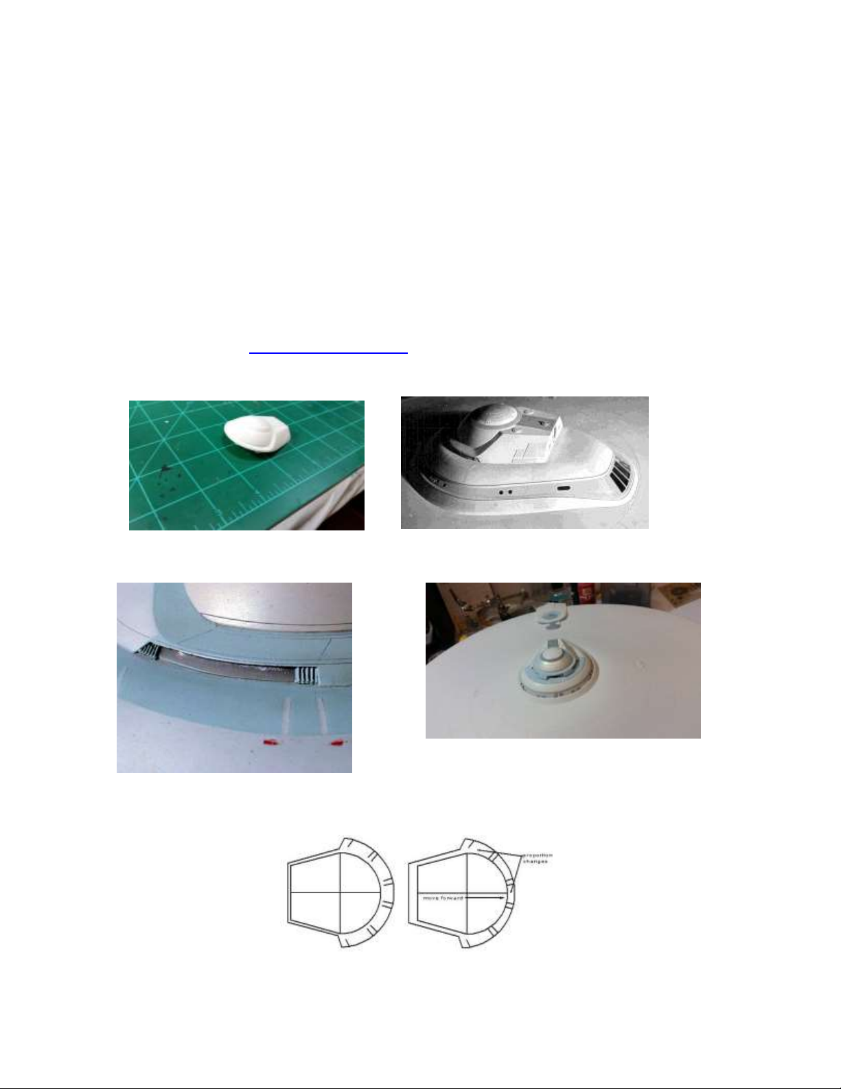
BRIDGE MODIFICATION
The bridge for the kit is, unfortunately, inaccurate and also does not allow for
lighting of the forward saucer registry spotlight as offered in the kit part. We
recommend purchasing a resin corrected bridge replacement part from Stellar Effects
Modeling Solutions as a quick, effective solution for solving the issue. The piece is not
only pre-designed to accommodate up to a 1.8mm LED for ease of installation of
lighting, it is also carefully designed to reflect the on-screen appearance of the bridge
deck and slotted windows as well as the sloped area at the base of the bridge where the
windows are. You can also choose to purchase other third party corrected bridge
modules or to modify the kit bridge piece yourself by installing a 1-2mm styrene riser
strip along the base of the piece (depending on what size LED’s you use to light the
registry) and cutting out the areas for the windows. You can refer to online videos as
well as the blog at www.stellareffects.com for instructions on how to do this
modification.
Kit part unaltered Studio Model Bridge
Stellar Effects Modeling Corrected Bridge
Studio Model Bridge Closeup
Bridge moved forward to correct position
8
BRIDGE BASE/BC DECK MODIFICATION
In addition to raising the bridge, you must also sand or file down the ridge on the
upper saucer bridge foot area and remove material as marked below to allow light to
come up into the bridge unit to light the windows. The bridge unit itself must also be
moved forward a few millimeters to sit in the accurate position and allow the proper
angle for the forward spotlight.
Black lines are the ridges that must be filed or sanded down. BE CAREFUL not to remove or damage the other raised detail
in this area!!! You can use masking tape to help somewhat. Area in center marked with an X should also be carefully removed with a
rotary tool sanding or grinding bit. DO NOT GO PAST PRE-DRILLED HOLE AREAS!!!
LOWER SAUCER AREA
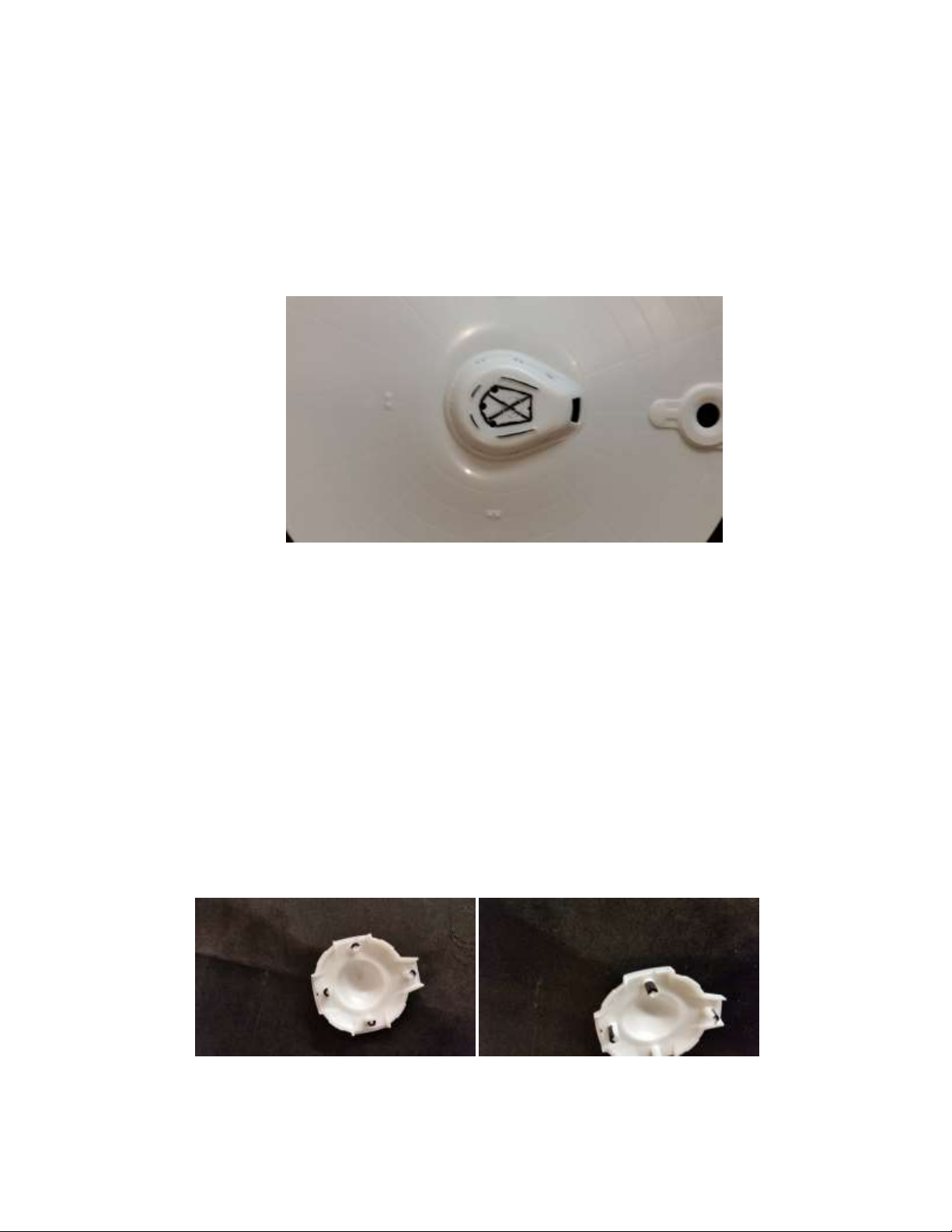
PLANETARY SENSOR ARRAY
The planetary sensor array presents a few challenges to modify for lighting and
offers several options to do so. One such option is shown below. Also, you may wish to
drill a hole for a 5mm LED in the center which can offer some ambient light into the
planetary sensor array. (optional)
Carefully remove HALF of each pin as shown to allow for lights/wires to pass through for planetary sensor spotlights
‘
9
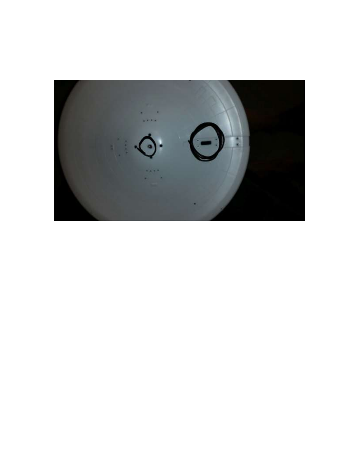
NECK HOLE FOR SAUCER WIRE CONNECTION TO BOARD
A hole must be made where the neck connects to the lower saucer to allow for
the JST Connectors and wire from the harness to come up from the secondary hull into
the saucer. Refer to the picture below for details.
Hole depicted in neck connection area should be cleared to accommodate the saucer connectors. Only one at a time needs to pass
through. Also note that a center hole in the planetary sensor area may be drilled to accommodate a 5mm LED for ambient light
PHASER HOLES FOR LASERS
Holes for the optional phaser lasers may be drilled into any phaser bank you
choose to mount lasers. You can mount lasers for a single bank or for all of them if you
choose. You must drill 3/32” holes angled the same direction you want to aim the lasers,
if using them, from the banks you mount the phasers. You should file or sand down the
turret nibs for each phaser bank you’ll be installing before drilling the holes. A pin vise
may give you more accurate angles as well.
Please note that the use of lasers, especially lasers not purchased with the Stellar
Effects Refit Signature Series Lighting and Effects Kit, may be dangerous. Avoid shining
lasers directly into the eyes of any person or animal as some lasers may damage the eye.
(*red lasers sold with the SFX Refit Signature Series are generally considered safe, but
we still recommend avoiding direct contact with the laser beam to any eyes!) Stellar
Effects is not responsible for any damages caused by the use of lasers, whether included
with the kit or purchased from a third party vendor.

10
SECONDARY HULL AREA
PYLON SPOTLIGHTS
The Enterprise kit does have holes already in place where the pylon spotlights
shine up on the pylons from the side walls. However, the pre-drilled holes angle straight
out, which do not allow the spotlights to shine up to the pylons at the proper angle. The
simplest way to fix this is to fill the holes with putty and carefully redrill them at an
angle in the desired direction with a pin vise and a 1/16” or 3/32” drill bit. The spotlight
holes are designated in the picture below. Dry fitting the pylons in place while installing
the lights will greatly aid in getting the proper spotlight direction. LOW TEMP hot glue
should be used to secure the LED in place once the light is aimed.
PYLON WIRE GROOVES
Grooves must be made where the two pylon pieces come together and join to the
secondary hull to accommodate the ribbon cables to the nacelles. The best way to make
these grooves is a flat sided jeweler’s file. Use the included pylon harness to mark off
the size to file, then carefully file the areas shown below on each pylon piece (both
sides) to make room for the wires. BE CAREFUL to avoid removing too much material
(cut too deep) or to damage the pylons themselves in visible areas! Removing too much
material may weaken the pylons causing a droop or break later!

11
*A NOTE ON PYLON PINS*
While not a specific lighting issue, it should be noted that the model kit has a
challenging fit issue where the pylons mount to the secondary hull. The pylon pins do
not go into the holes correctly, which causes the pylons not to seat where they’re
supposed to causing fit issues and gaps. This can be corrected by altering the pylon pins
slightly. Refer to YouTube videos for more information or contact us and check the
website blog at www.stellareffects.com for specific instructions.
DEFLECTOR HOUSING/RCS THRUSTERS
The deflector housing incorporates a bi-color LED for the main forward deflector.
This lighting kit is designed for a specialized NEOPIXEL LED depending on what’s
included. If using a 5mm LED, you will need to increase the hole size in the center of the
deflector housing to accommodate a 5mm LED. (Use previous chart for non-metric
conversion bit size)
Additionally, you will need to drill 4 holes in the RCS thruster areas to allow light
from the LED’s to shine through. Use a 2mm or 3/32” drill bit to give you the proper size
to install the RCS thrusters.
There are 4 of these areas around the deflector housing. Each must be drilled.

12
NACELLES
The only area on the nacelles that requires a modification is the outer piece at
the rear fin area to allow the RCS Thruster light to shine through. Use a 2mm or 3/32”
drill bit for a 1.8mm LED or a 1/8” bit for a 3mm LED to accommodate the LED you
choose to install. (refer to your lighting kit part) Hole must be centered perfectly in the
ridge, then light blocked on both sides to prevent light bleed!
A second option is to remove the tab on the fin part and increase the hole already drilled where the fin would have
joined the nacelle. Either way is effective.
MOUNTING POLE HOLE
A hole must be drilled in the area where the mounting post attaches to the
model (newer Round 2 release) or the second deflector housing piece to accommodate
the main power cable from the board. Remove the material leaving enough for the pole
to keep from passing too far into the model, but allowing for the wires to go throught
the pole into the model and secondary board.
13
Soldering an LED
We realize not everyone has experience with electronics and, in particular, using
a soldering iron. So the Stellar Effects team thought it would be a good idea to include a
little basic tutorial here to make this process simple for you. With just a little bit of
practice, you can solder an LED like the pros! Let’s check it out… (if you’re familiar with
this technique, feel free to skip to the next section)
Obviously, the first thing you’ll need is an LED and a resistor. For this example,
we’re using a 5mm Cool White LED and a standard 470 or 560 ohm resistor, like most of
the resistors included in your kit. These resistors are designed for a 9V or 12V power
source. Use a resistor calculator (or “Ohm’s Law”) for help in finding out which ohm
rating you need for your power source if using something different. Your kit comes with
appropriate resistors for the included power source. (Deflector/Impulse resistors may
be different as those effects connect to a 5V terminal instead of the higher 9V or 12V)
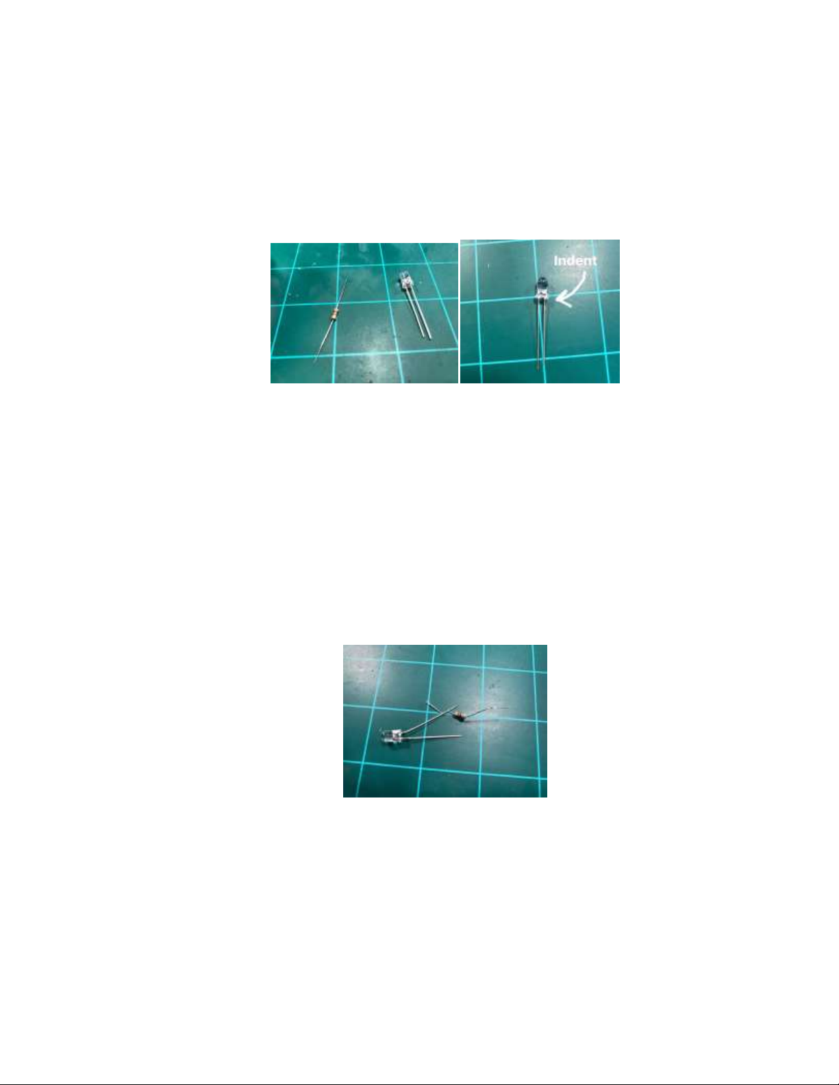
Notice on your LED that each has a long metal lead and a shorter one. In almost
all cases, the longer leg is positive and the shorter leg is negative. Also, on 3mm and
5mm LED’s, there is a noticeable indentation on the very low ring around the base of
the bulb on the negative side. These will help you know which lead is which.
The first step is to wrap one metal lead (leg) of the resistor around one lead (leg)
of the LED. NOTE: It does not matter which leg of the resistor goes on the LED leg as
resistors are not polarized. Also NOTE: The resistor can be put onto EITHER leg of the
LED. However, we strongly recommend always choosing the same one. (we tend to
choose positive, as shown, because that’s how we were each taught, but it doesn’t
matter) The reason to always use the same leg is so that, once you clip off any excess
metal on the leg of the LED, you’ll still know positive from negative.
14
Soldering an LED (pg2)
Next, slide the coiled resistor up the LED leg a bit and apply the solder by
touching the iron and the tip of the solder coil to the wrapped resistor. For most LED’s,
you should keep your soldering iron from 335˚C to 400˚C. Leave just enough solder to
secure the two wire leads together. Then trim the excess wire from the LED leg and the
resistor leg, making sure not to cut into the solder itself and separate the two again.
Next, repeat the same process with the wire by coiling about a cm of exposed
(stripped) wire around the other end of the resistor and adding solder the same way.
Then repeat this step for the negative wire and LED leg. (NOTE: you only need a resistor
on one LED leg. We recommend keeping it consistently on either the positive or
negative side for all of your LED’s so they’re easy to identify if you trim them and aren’t
sure which side you used) Again, trim off any excess LED leg metal.
Finally, twist your attached wires tightly for a tidy finish, strip off a little shielding
at the end of the wire, and you should be done! Test your LED by connecting the
negative wire to negative on your power source and positive to the positive. (in this
case, 9V-12V) If you see light, you’ve got it right!

15
Soldering an LED STRIP
LED strips are convenient for several lighting needs! They are prewired with
resistors to operate at 9V –12V and may be cut every third LED into smaller strips.
However, when cutting the LED strip, you must add solder to the connection points on
the strip. This process is actually fairly simple and, since you don’t need a resistor for the
strips themselves, it is a fast and easy process.
Notice that at the connection points, there is a positive side and a negative side.
This is where we will add some solder before attaching the wire. (called “tinning” the
solder point) Again, touch the solder coil and soldering tip together to the copper solder
points, not just the iron tip with solder on it. “Drag” the melting solder from the solder
coil onto the copper pads. You should have a small bead of solder at the point when
finished.
Next, strip off only about a half a millimeter of wire to attach to the points.
Simply touch the iron tip to the solder point to re-melt the solder and slip the exposed
wire into it and remove the iron, holding the wire still a second or two until the solder
hardens. Repeat the process for both positive and negative contact points. That’s it! It’s
wired!

16
Wiring tips and tricks
“How do those pro and advanced builders get such tidy wires without a rat’s
nest?” We hear this question a lot. The trick is learning to be efficient with your wiring.
It’s also important to understand current, voltage, and terms such as “common ground,”
“common positive (hot),” and other terms and concepts such as voltage drop. For our
purposes, we’ll focus on “common” connections. This concept basically uses the idea
that you can connect either a positive or negative leg of one LED (with proper resistors)
to another one on the same wire and terminal and they’ll share the terminal’s function.
For the Refit Signature Series kit, most of the effects terminals, except the deflector
terminal, are negative. (you’ll connect the negative wire of the LED’s to this terminal to
get the effect and the positive to the 12V terminal) This means that, while different
LED’s in one section may all be on separate effects, they can share one common 12V
positive wire. Therefore, if you plan out your wiring carefully, almost all the LED’s in,
say, your saucer section can have one positive wire spliced from each LED and strip to
the next with only a single positive wire having to go back into the harness 12V terminal
instead of all of the positive wires from each LED. Talk about a space saver!
The negative wires will each go to their respective effects terminal. But you can
share the wires from each effect as well if multiple LED’s have the same effect. For
example, each NAV light can share one negative wire. Then you can do the same for
shared strobe (STR) lights, for instance.
To achieve this “common” wiring, you will need to learn how to make a “splice”
and a “pigtail” with your wires. A splice is simply twisting two exposed sections of wire
together and soldering them together. You can also twist the two wires together, then
around an LED or resistor leg to have two wires attached to that leg, one that can go
back to the terminal and the other to the next LED or strip. (NOTE: Each LED will still get
its own resistor!) That basically makes it where the two wires are joined together to
become one common wire. You’d simply connect the positives of each splice to the next
LED positive leg and splice another there to go to the next.

17
A “pigtail” is similar to a splice except, in this case, we’ll twist multiple (common
positive, for example) wires together from several LED’s with one additional wire
attached to go back to the terminal. That way, instead of trying to fit 10 wires into one
terminal, you can simply have one. You will likely want to cover up the splice point of
the pigtail with electrical tape or shrink tubing to avoid any possibility of crossing other
wires and causing a short.
One more trick is using LED strips as a contact point for other LED’s. (as long as
either the positive or negative wires or both connect to the same voltage and/or effects
terminal) In the picture below, you can see where an LED has been attached to the LED
strip on the contact points opposite of the wire end. The attached LED will behave with
the same effect and button functions as the LED strip it’s attached to.
We hope some of these tricks make sense and help you with your wiring to keep
things neat and tidy! Feel free to practice with spare LED’s and strips, if you have some.
The more you do these steps, the easier it gets!

18
The STELLAR EFFECTS
REFIT SIGNATURE SERIES
MAIN CONTROL BOARD
Let’s take a look at the layout of the primary control board for the SFX Refit Signature Series
Lighting and Effects kit.
SFX REFIT SIGNATURE SERIES MAIN CONTROL BOARD
You will notice that there are green terminal blocks with screws on the tops of each
terminal. These terminals are where your wires will connect. Each terminal is marked both on
the primary board and with a color-coded label on the front face where the wire is inserted. To
connect a wire to a terminal, simply loosen the top screw, insert the wire with about 5mm of
exposed wire on the end into the terminal in the front edge, and tighten the top screw back
down. TIP: if you only have one wire inserted into a terminal, it may not allow the screw to
tighten onto it enough to hold it in the terminal. To fix this, make a “hook” on the exposed wire
(bending it back on itself) so that it will hold better. If you are using the included wire-wrapping
wire, it is easily stripped with a 28 or 30 AWG wire stripper or by just using your fingernail.
The color-coded labels will help you to determine which wires will connect where on the
board as the effects terminal label colors will match the same color as the wire to LED or other
effects component. There will be some repeated colors, but the harness is designed to help
reduce the number of repeated colors in any one area of the ship. Where repetition of wire
colors was unavoidable, wires should be twisted together such that no colors are reproduced in
one grouping. For instance, if you have a harness grouping of four different color wires twisted
together, avoid twisting another group of wires with the same four colors so that you can
identify the wires by the groups they’re in.
19
Let’s take a closer look at each terminal and its function:
MAIN POWER IN/OUT:
GR –This is the main GROUND (Negative) input from your main power supply wire
12V- This is the main 12V Positive input from your main power supply wire
12V(out) –This is an additional 12V Positive output terminal if needed.
PRIMARY INTERIOR/EXTERIOR/STARTUP
LIGHTING SIDE:
12V- This is a 12V Positive output terminal. Use for any 12V positive (WHITE wire) component
connection. Except the positive wire from the Neopixels for the Forward Deflector and Impulse
Crystal and the positive wire from the lasers for the Phasers, (if using lasers) all other positive
wires for components will connect to one of these 12V output terminals using a WHITE wire and
proper resistor. (Included)
5V –This is a 5 Positive output terminal. Use for any 5V positive (RED wire) component such as
lasers for the phasers and Neopixels for the deflector and impulse crystal. No additional resistor
is needed for those components if connecting to 5V.
GR –This is a GROUND (Negative) output. You should only need this for the Neopixels for the
deflector and impulse crystal. Additionally, you can use it for any light you want to be on
constantly, but understand that any lights connected (other than the Neopixels) will also be on
before the startup and initialization sequences as well as if the rest of the ship is fully shut
down. It is not recommended to use this terminal for anything other than the Neopixels.
MAIN SAU/M1 –This terminal is where the negative wire (GRAY) main interior lights for the
saucer will connect. It is interchangeable with and will function the same as the MAIN EHULL
terminal, but it is best to separate the two sections due to the amperage requirements for the
LED strips. If you are using the SFX Refit Signature Series lighting harness, the GRAY wire from
the B and D harness tethers will connect here.

20
MAIN EHULL/M2 –This terminal is where the negative wire (GRAY) main interior lights for
the secondary E-Hull will connect. It is interchangeable with and will function the same as the
MAIN SAU terminal, but it is best to separate the two sections due to the amperage
requirements for the LED strips.
RCS THR/RCS –This terminal controls the yellow RCS thruster lights at various points
throughout the ship. You will connect the negative wire (YELLOW) from the RCS thruster LED’s
and/or the harness tether wires from the Nacelles and Saucer B tether here.
PYL/PY –This terminal controls the pylon spotlights in the secondary E-Hull. Connect here with
an ORANGE wire connected to the negative leg of the components.
FWD NAC/FN –This terminal is for the Forward Nacelle Spotlights on the front side of each
warp nacelle. Connect the negative leg of the LED’s to this terminal (or the harness terminal)
with a GREEN wire.
NECK/NK –This terminal is for the Neck Spotlights in the E-hull. Connect the negative leg of
the LED’s to this terminal with a BROWN wire.
NAC REG/RN –This terminal is for the Nacelle Registry Spotlights in the aft section of the
nacelles. (For tips on how to illuminate the registries, see the section on Raytheon lighting)
Connect the negative leg of the LED’s to the terminal (or harness) using a PURPLE wire.
PLA SEN/PL –This terminal controls the spotlights in the Planetary Sensor Array at the
bottom of the saucer. Connect the negative leg of the LED’s to the terminal (or harness
terminal) using a YELLOW wire.
BR SPOT/BR –This terminal is for the forward registry spotlight from the Bridge that
illuminates the ship’s main registry markings on the top of the saucer. Connect the negative leg
of the LED’s to the terminal (or harness terminal) using an ORANGE wire.
EHULL SPOT/EH –This terminal is for the side E-hull registry spotlights. Connect the
negative leg of the LED’s to the terminal using a YELLOW wire. (For tips on how to illuminate the
registries, see the section on Raytheon lighting) If using the Shuttle Bay Board, the rear
Raytheon light attached to the board there can alse be connected to this terminal with a
YELLOW wire. If you are not using the SFX Shuttle Bay Board, you can connect a standard LED
here with a YELLOW wire to the negative leg to illuminate the aft registry beneath the bay
doors.
WEAPONS LIGHTING SIDE:
PHA1/PH1 and PHA2/PH2- These terminals control the phasers. The negative side of the
components you use (Lasers or LED’s) will connect here (or to the harness terminals) with
PURPLE wires. If you are using lasers, no resistors will be needed. You may connect as many
phaser ports as you wish to these terminals. Phasers will alternately fire from PHA1 to PHA2. It
really doesn’t matter which side fires first, but you are free to decide on your own if it is
important.
Table of contents


