446‐AVR
Sensoreinerzialeincontenitoreautoprotetto/Inertialsensorintamperedhousing
Cooper CSA S.r.l. - via Meucci, 10 - 20094 Corsico (MI) - Italy
Tel: +39 02.458.79.11 - Fax: +39 02.458.79.105 - www.coopercsa.it Rif. 08902-B_04
DESCRIZIONE
Sensore inerziale in contenitore termoplastico bianco protetto all’apertura da Switch di tamper. Scheda d’analisi a basso assorbimento con trimmer per la regolazione della
sensibilità. Collegamento a morsetti.
CARATTERISTICHE TECNICHE
Alimentazione Da 2,5 a 5 Vcc Tecnologia Microprocessore, SMD
Assorbimento standby 16 μA ; V = 3Vcc Regolazioni Sensibilità tramite trimmer
Assorbimento in allarme 400 μA ; V= 3Vcc (t = 0,5s) Programmazione Par. tramite switch di tamper
Morsetti 6 x 1,5 mm² Dimensioni 110 x 32 x 39 mm
Protezioni inversione dell’alimentazione (cortocircuito)
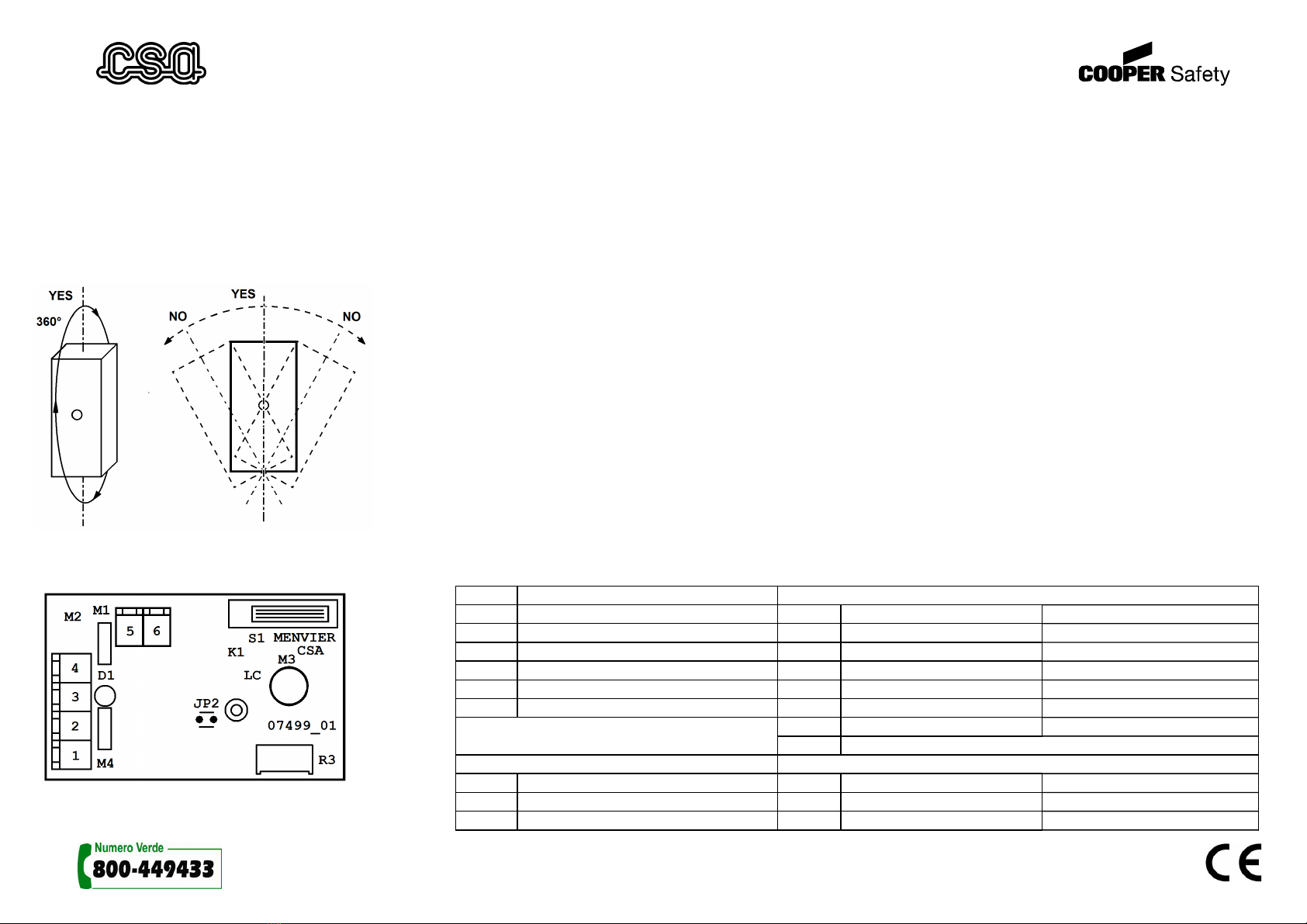
Fig. 1
INSTALLAZIONE (vedi Fig. 1)
Può essere installato in tutte le posizioni del suo asse verticale per 360° senza però essere inclinato
COLLEGAMENTI (vedi Fig. 2)
cpositivo dnegativo euscita A fuscita B gcontatto di tamper hcontatto di tamper
PROGRAMMAZIONE PARAMETRI
Inserendo il jumper JP2 si entra in modalità programmazione, evidenziata dal lampeggio del led che visualizza, tramite
il numero di accensioni, il parametro selezionato seguito da un numero di accensioni più rapide, che indicano il valore
del parametro. Per modificare l’impostazioni della scheda, collegare fra loro i morsetti 3-5 e 4-6 ed alimentare il
circuito fra i morsetti 1-2. Inserire il jumper JP2. Il led lampeggia indicando l’item1 ed il suo valore. Premere e
rilasciare una volta lo switch di tamper per accedere all’item successivo. Per modificare il valore dell’item desiderato,
tenere premuto lo switch per circa 2 Sec. fino a quando il led di spegne. A questo punto il led indica solo il valore
assunto dall’item in questione. Premere e rilasciare più volte lo switch per selezionare il valore desiderato. Tenere
premuto lo switch fino allo spegnimento del led per tornare alla selezione dell’ item. Una volta modificati i parametri
occorre entrare nell’ Item 5 e selezionare il valore 2 per memorizzare in modo permanente i nuovi valori nella
memoria. Rimuovere il Jumper e generare un allarme, la scheda adesso funzionerà in accordo ai nuovi parametri
introdotti. La scheda viene programmata in fabbrica, con si seguenti valori: Uscita A = 2 (attivo basso), Uscita B = 1 (
attivo alto ) Modo Led = 1 (non attivo) , Tempo di allarme = 2 ( 500mS)
FUNZIONE MODO DI USCITA
Valore Valore Stato logico a riposo Stato logico in allarme
1 Modo Uscita A 1 0 1
2 Modo Uscita B 2 1 0
3 Modo Led 3 0 Alta impedenza
4 Tempo di allarme 4 1 Alta impedenza
5 Mem. Parametri 5 Alta Impedenza 1
6 Alta Impedenza 0
7 Ingresso Reset ( attivo basso: spegne il led)
MODO LED TEMPO DI ALLARME
1 Non attivo 1 250 ms
2 sempre acceso se rilevato allarme 2 500 ms
3 Segue allarme 3 1000 ms
Fig. 2