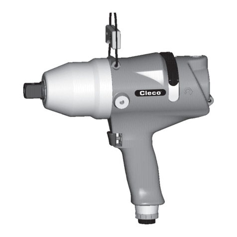
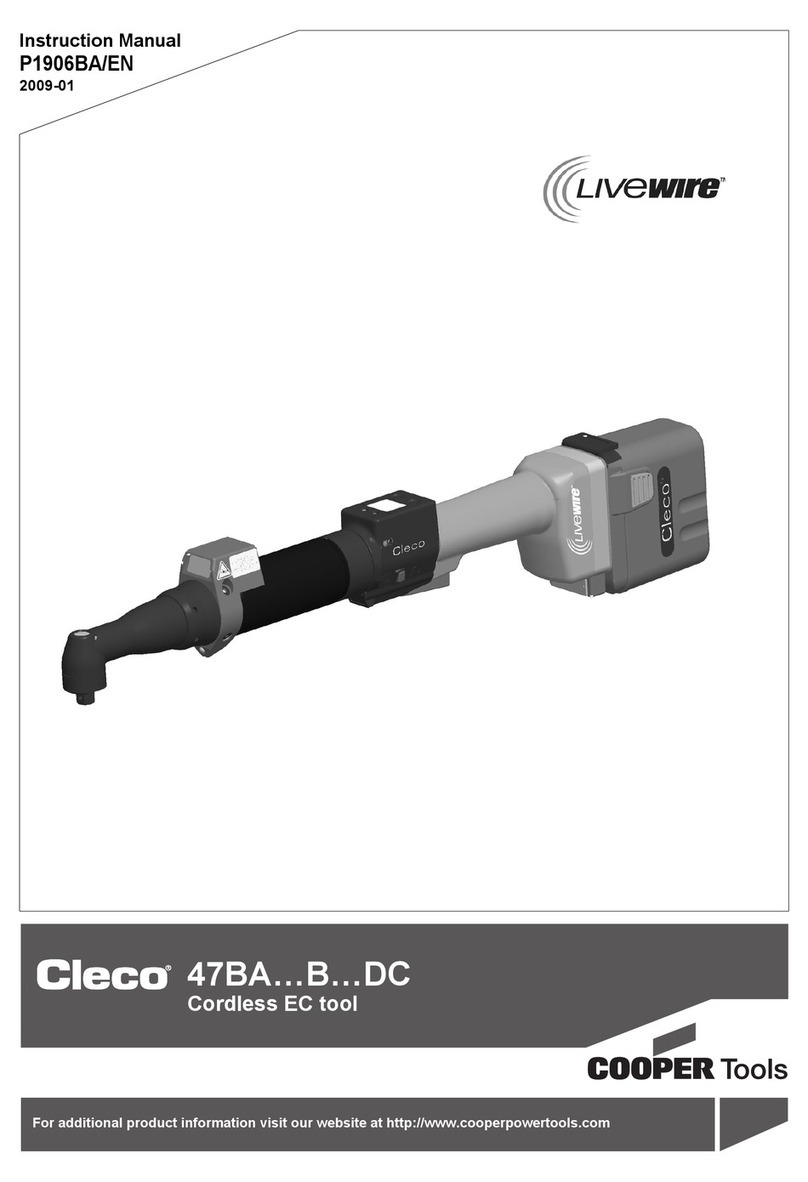
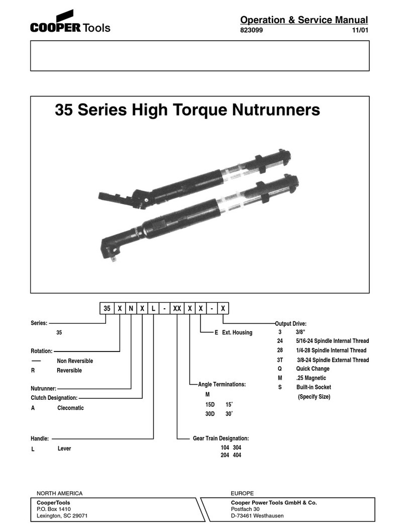
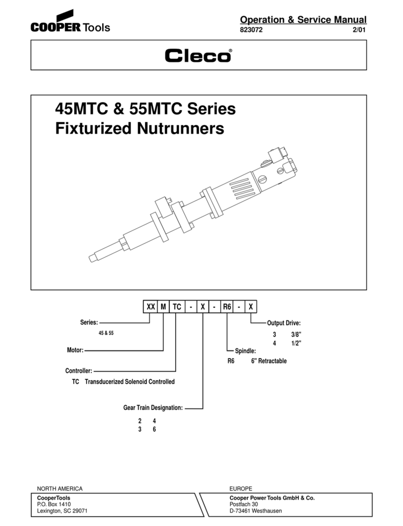
Cooper Tools Cleco 88 Series Installation and operating instructions

1
Operation & Service Manual
823020 2/01
8 & 88 Series Fixturized Nutrunners
X
Throttle Designation:
Gear Train Designation:
TransducerT
Lever
Options:
L
XX
Torque Control Mechanism:
Clecomatic
Rotation:
Reversible
Non Reversible
Stall Type
A
R
Motor:
8 & 88
Series:
MXXXXXX -
Angle Terminations:
K
M
H
75Nm Offset
5" Retractable
Spindle:
OS75
R5
XX- X-
1/2"
3/8"3
4
Output Drive:
1/4"2
2
5
7
10
20
30
40
54
74
104
204
NORTH AMERICA EUROPE
CooperTools
P.O. Box 1410
Lexington, SC 29071
Cooper PowerTools GmbH & Co.
Postfach 30
D-73461 Westhausen

2
CAUTION!
Personal hearing protection is
recommended when operating
or working near this tool.
Safety Recommendations
For your safety and the safety of others, read and
understand the safety recommendations and operating
instructions before operating any tool.
Always wear protective equipment:
For additional information on eye protection and face
protection,refertoFederalOSHARegulations,29Code
of Federal Regulations, Section 1910.133., Eye and
FaceProtection,andAmericanNationalStandardsInsti-
tute,ANSIZ87.1,OccupationalandEducationalEyeand
Face Protection. Z87.1 is available from the American
National Standards Institute, Inc., 11 West 42nd Street
New York, NY. 10036.
Hearing protection is recommended in high noise areas
85 dBA or greater. The operation of other tools and
equipmentinthearea,reflectivesurfaces,processnoises
and resonant structures can substantially contribute to,
and increase the noise level in the area. Excessive air
pressureabove90PSIGorwornmotorcomponentscan
also increase sound level emitted by tool. For additional
informationonhearingprotection,refertoFederalRegu-
lations,Section1910.95,OccupationalNoiseExposure,
andAmericanNational StandardsInstitute,ANSI S12.6,
Hearing Protectors.
Cleco tools are designed to operate on 90 psig (6.2 bar)
maximum air pressure. If the tool is properly sized and
applied, higher air pressure is unnecessary. Excessive
airpressure increasestheloadsandstresses onthetool
parts,sockets,andfastenersandmayresultinbreakage.
Installationofafilter-regulator-lubricator intheairsupply
line ahead of the tool is recommended.
Before the tool is connected to the air supply, check the
throttle for proper operation (i. e., throttle moves freely
and returns to closed position). Being careful not to
endangeradjacentpersonnel,cleartheairhoseofaccu-
mulated dust and moisture. Before removing a tool from
serviceorchangingsockets,makesuretheairlineisshut
off and drained of air. This will prevent the tool from
operating if the throttle is accidently engaged.
Someindividuals
may be suscep-
tible to disorders
of the hands and
arms when per-
forming tasks
consisting of
highly repetitive
motionsand/orexposuretoextendedvibration.Cumula-
tive trauma disorders such as carpal tunnel syndrome
and tendonitis may be caused or aggravated by repeti-
tious,forcefulexertionsofthehandsandarms.Vibration
may contribute to a condition called Raynaud's Syn-
drome. These disorders develop gradually over periods
of weeks, months, and years. It is presently unknown to
what extent exposure to vibrations or repetitive motions
may contribute to the disorders. Hereditary factors,
vasculatoryorcirculatoryproblems,exposuretocoldand
dampness,diet,smokingandworkpracticesarethought
to contribute to the conditions.
Any tool operator should be aware of the following
warning signs and symptoms so that a problem can be
addressed before it becomes a debilitating injury. Any
tool operator should be aware of the following warning
signsandsymptomssothataproblemcanbeaddressed
beforeitbecomesadebilitatinginjury.Anyusersuffering
prolongedsymptomsoftingling,numbness,blanchingof
fingers, clumsiness or weakened grip, nocturnal pain in
the hand, or any other disorder of the shoulders, arms,
wrists, or fingers is advised to consult a physician. If it is
WARNING!
Impact resistant eye protection
must be worn while operating
or working near this tool.
Repetitive work motions and/or vibration
may cause injury to hands and arms.
Use minimum hand grip force consistent
with proper control and safe operation.
Keep body and hands warm and dry.
Avoid anything that inhibits blood circulation.
Avoid continuous vibration exposure.
Keep wrists straight.
WARNING
!
Avoid repeated bending of wrists and hands.

3
Safety Recommendations
determined that the symptoms are job related or aggra-
vated by movements and postures dictated by the job
design,itmaybenecessaryfortheemployertotakesteps
to prevent further occurrences. These steps might in-
clude, but are not limited to, repositioning the workpiece
or redesigning the workstation, reassigning workers to
other jobs, rotating jobs, changing work pace, and/or
changingthetypeoftoolusedsoastominimizestresson
theoperator.Sometasksmayrequiremorethanonetype
of tool to obtain the optimum operator/tool/task relation-
ship.
The following suggestions will help reduce or moderate
the effects of repetitive work motions and/or extended
vibration exposure:
• Use a minimum hand grip force consistent with
proper control and safe operation
• Keep body and hands warm and dry (cold
weather is reported to be a major factor contrib
uting to Raynaud's
Syndrome)
• Avoid anything that inhibits blood circulation
—Smoking Tobacco (another contributing
factor)
—Cold Temperatures
—Certain Drugs
• Tasks should be performed in such a manner
that the wrists are maintained in a neutral posi-
tion, which is not flexed, hyperextended, or
turned side to side.
• Stressful postures should be avoided — select
a tool appropriate for the job and work location
• Avoid highly repetitive movements of hands
and wrists, and continuous vibration exposure
(after each period of operation, exercise to
increase blood circulation)
• Keep tool well maintained and replace worn
parts
Work gloves with vibration reducing liners and wrist
supportsareavailablefromsomemanufacturersofindus-
trial work gloves. Tool wraps and grips are also available
from a number of different manufacturers. These gloves,
wraps, and wrist supports are designed to reduce and
moderate the effects of extended vibration exposure and
repetitive wrist trauma. Since they vary widely in design,
material,thickness,vibrationreduction,andwristsupport
qualities, it is recommended that the glove, tool wrap, or
wrist support manufacturer be consulted for items de-
signed for your specific application. WARNING! Proper
fit of gloves is important. Improperly fitted gloves
may restrict blood flow to the fingers and can sub-
stantially reduce grip strength.
Warning Labels
The warning labels found on these tools are an essential
partofthisproduct.Labelsshouldnotberemoved.Labels
shouldbecheckedperiodicallyforligibility.Replacewarn-
ing labels when missing or when the information can no
longer be read. Replacement labels can be ordered as
any spare part.
Extension Neutral Flexion Radial Deviation Neutral Ulnar Deviation
Avoid Avoid Avoid
OK Avoid OK

4
DISASSEMBLY — GENERAL (ALL MODELS)
Unscrew (left hand threads) and remove the spindle assembly
No. 281345. Unscrew the gear case assembly and unplug the
transducer wiring . Then remove the gear case and transducer.
Push the wiring back into the connector block No. 203152. The
motor unit may now be removed from the backhead. See the
following paragraphs for complete disassembly instructions on
the various subassemblies.
CLUTCH DISASSEMBLY
Unscrew the adjustment nut, No. 867875. That will release the
adjustment lock plate No. 867876, both bearing races No.
863455, thrust bearing No. 847104, torque spring No. 867938,
ball retainer No. 867881, and six (6) steel balls No. 842162.
Wash the spindle assembly in a solvent. Remove the ball
retainer ring, No. 867923, and ball retainer plug, No. 867908.
Rotatetheclutchspindletoallowthesixteen(16)steelballs,No.
844265, to drop out of the ball loading hole located in the clutch
cam, No. 867892. Separate the, clutch spindle and clutch cam
beingcareful not tolose the resetpin,No. 867888;resetspring,
No. 867895; sear plunger, No. 867886; plunger spring, No.
867896; and sear pin, No. 867909.
TRANSDUCER DISASSEMBLY
Removetheringgear and transducerassemblyfromtherearof
the transducer housing. Remove the retainer ring No. 619017,
from the transducer and tap lightly on a soft surface to remove
bearing No. 847566. Then remove the transducer from the rear
of the ring gear.
GEAR CASE DISASSEMBLY
Single Reduction — 20 Gear Trains
The spider should be pressed out the rear of the gear case.
RemovetheretainerringNo.844364,andpressthebearingNo.
847147, out the front of the gear case.
Ifreplacementoftheidlergearpinsisnecessary,theyshouldbe
pressedouttherearofthespider.SeeFig.1forreplacementpin
height.
Fig. 1 — Single Reduction Spider
Multiple Reduction — -2, -5, -7, -10 Gear Trains
All spiders should be removed from the rear of gear case.
RemovetheretainerringNo.844364,andpressthebearingNo.
847147, out the front of the gear case.
Ifreplacementoftheidlergearpinsisnecessary,theyshouldbe
pressedouttherearofthespider.SeeFig.2forreplacementpin
height.
2nd Reduction 1st Reduction
Spider Spider
Fig. 2 — Double Reduction Spiders
OPERATING & SERVICE INSTRUCTIONS
The torque of the 8MT & 8M nutrunner is controlled by the use
ofapressureregulatortochangethestalltorqueofthetool.The
torque of the 8MA nutrunner is controlled by the use of a
CLECOMATIC automatic shut-off clutch. Accurate torque is
achieved by setting the CLECOMATIC clutch to the desired
torque.
CLUTCH ADJUSTMENT
Shut off air supply to the tool and rotate the adjustment cover,
No. 202829, 180°to uncover the adjustment slot in the clutch
housing. Rotate the spindle until the hole in the adjustment nut
isvisibleintheslot.Use
a 1/8" (3mm) diameter
pin to hold the nut. Use
a suitable tool to turn
the spindle in a coun-
terclockwisedirectionto
increase torque or
clockwise to decrease torque. Return the ad-
justment cover to its closed position after every
adjustment. Note: If the clutch is adjusted over the
maximumpoweroutputofthetool,theclutchwillnotfunction
and the tool will operate like a stall-type tool. Also, if the tool is
being operated at its upper torque limits, a drop in air pressure
could cause the clutch not to function due to a loss of motor
power and the tool will function like a stall-type tool.
FLOW VALVE
The flow valve No. 203036, can be adjusted with a screwdriver
clockwise to lower the RPM and counterclockwise to raise the
RPM of the tool.
AIR SUPPLY
Thetool isdesignedto operateat90 psig(6.2bar) airpressure.
Theairpressureshouldbecheckedatthetool'sairinletwhilethe
tool is running. For maximum performance, use a 5/16" I.D. air
hoseup to 8'inlength. Ifadditionallength isrequired,a 3/8"I.D.
or larger hose should be connected to the 5/16" I.D. hose.
LUBRICATION
An automatic in-line filter-regulator- lubricator is recommended
asitincreasestoollifeandkeepsthetoolinsustainedoperation.
Thein-linelubricatorshouldberegularlycheckedand filled with
a good grade of 10W machine oil. Proper adjustment of the in-
line lubricator is performed by placing a sheet of paper next to
theexhaustportsandholdingthethrottleopenapproximately30
seconds. The lubricator is properly set when a light stain of oil
collects on the paper. Excessive amounts of oil should be
avoided.
Applicationofthetoolshouldgovernhowfrequentlyitisgreased.
It is recommended that the idler gears and right angle gears
receive a generous amount of NLGI 2-EP grease through the
grease fittings after 40 hours of operation.
STORAGE
In the event that it becomes necessary to store the tool for an
extended period of time (overnight, weekend, etc.), it should
receivea generousamountof lubricationatthattimeandagain
when returned to service. The tool should be stored in a clean
and dry environment.
OFF
.240
.255
Front Rear
.360
.375
Front Rear
.240
.255
Front Rear

5
CLUTCH REASSEMBLY
During reassembly of the clutch, all parts should receive a thin
coating of a mixture of 10W machine oil and NLGI 2-EP grease.
When installing the sear pin, No. 867909, the rounded end goes
into the clutch cam first. The sear plunger, No. 867886, goes into
the clutch cam cupped end first. All parts installed into the clutch
spindle and clutch cam, No. 867892, should be checked for
smooth operation before complete assembly of the clutch.
"H" RIGHT ANGLE HEAD ASSEMBLY
Thedrivengearandspindleballbearing847846,arepressedonto
the spindle shaft. Insert spindle shaft and gear into housing and
replaceretainerringNo.869033.Installthepiniongearandrelated
components into the rear of the angle head.
"K" RIGHT ANGLE HEAD ASSEMBLY
Slip pinion needle bearing, No. 869864, (unstamped end first) on
thepinionNo.202200,andpress(pressonthebearing'sstamped
end) the bearing in to a depth of 7/8" from the face of the bearing
bore. Install pinion ball bearing, No. 847846 and bearing retainer,
No. 863564, in the head and tighten retainer securely using the 5/
8"hexnutand5/8"deepsocket.Usingasuitabledriverthroughthe
hole in the top of the head, drive the pinion back to make sure it is
seated properly in the head.
"M" RIGHT ANGLE HEAD ASSEMBLY
Assemble the spindle and related components in the head and
securely tighten (left hand threads) the bearing cap, No. 864396.
Use bearing spacer, No. 869050, to press the pinion needle
bearing, No. 863360, (press on the bearing's stamped end) in the
head. Install ball bearing, No. 847846, and bearing retainer, No.
863564, in the head and tighten retainer securely using the 5/8"
hex nut and 5/8" deep socket.
TRIP ROD SIZING
A. Old Trip Rod
Thetoolshould bereassembledcomplete less thetriprod, clutch,
and clutch housing. With the air on, install the trip rod and clutch
intothetoolandmeasurethedistancebetweentherearfaceofthe
ballretainer,No.867881, and thefrontfaceofthegearcase. Turn
the air off and depress the clutch assembly and measure clutch
travel.Clutchtravelmustbeatleast3/32".Ifnot,thetriprodshould
be replaced.
B. New Trip Rod
Assemble the tool completely, less the clutch housing, and con-
nect the tool to the air supply. Screw (left hand threads) the clutch
housing onto the gear case until air exhausts from the backhead.
Measurethegapbetweentheclutchhousingandgearcase.Grind
this amount plus 5/64" minimum off the trip rod. IMPORTANT
NOTE: If the trip rod is too long the tool can ratchet or not shut off.
If the tool has a drop in power or RPM the trip rod can be to short.
Remember the trip rod length is not the only factor that causes
these problems. If you feel sure you have cut the trip rod length
properly look for other problems.
MOTOR DISASSEMBLY
Use a soft-faced hammer to drive the rotor out of the front rotor
bearing. This will allow the cylinder and four (4) rotor blades to be
removedfromtherotor.Settherearbearingplateonthe vise jaws
with the rotor hanging down. Use a 7/32" punch to drive the rotor
out of the rear rotor bearing.
BACKHEAD DISASSEMBLY
Unscrewand removethe inletbushing No.202883, for inspection
andcleaningoftheairinletscreenNo.833300.Replacethescreen
if clogged or torn. Remove flow valve No. 203036, by removing
retainer ring No. 864271, then unscrewing flow valve with screw-
driver.
REASSEMBLY — GENERAL
Allparts shouldbe washedin a solventand inspectedfor damage
orwear.Particularattentionshouldbegiventoallbearings,gears,
gear pins, and rotor blades as failure of these parts could cause
damagetomoreexpensiveparts.Rotorbladesshouldbereplaced
if they measure less than 3/16" on either end.
Inspectandreplaceany"O"-ringsorsealsthatshowsignsofwear
or deterioration. All gears, gear pins, and open bearings should
receiveagenerousamountofNLGI2-EPgrease duringreassem-
bly.
Reassembly of all of the various subassemblies is in the reverse
orderofdisassembly;however,thefollowingparagraphslistsome
of the more important reassembly procedures.
MOTOR REASSEMBLY
Assemble the rear rotor bearing and rear bearing plate (press on
the bearing's inner race) onto the rear rotor shaft until there is
approximately .0015" clearance between the plate and rotor.
Assemble the four (4) rotor blades, cylinder, front bearing plate,
and front rotor bearing (press on the bearing's inner race) to the
rotor assembly. After final assembly, the cylinder should be held
firmly, but not tightly between the two (2) bearing plates and the
rotor should turn freely and not rub either bearing plate.
Must be replaced if less than
3/16" (4.7mm) on either end.
.0015" (.038mm)
Clearance

6
TRANSDUCER SPECIFICATIONS
MAXIMUM TORQUE CAPACITY 25.0 ft. lbs. (33.9 Nm)
OUTPUT VOLTAGE (Vo) 2 Millivolts per volt at maximum torque capacity
BRIDGE RESISTANCE (Rbr) 700 ohms (nominal) can be used with 350 and 700 ohm strain gage equipment*
TRANSDUCER CONNECTOR Mates with Cannon KPT01/MS3111-6S or equivalent
CALIBRATION INSTRUCTIONS
In order to calculate the calibration value for the system in % full scale, the following formula may be used:
% FS = Rbr 1 1
------------------ X ----- X -----
2(Rcal) + Rbr Vo 2
Where Rcal = Calibration Resistor Value in ohms of the torque monitor used.
The following is an example of a 8 series tool and a torque monitor with a 110 kohm calibration resistor.
The values are: FS = 25.0 ft. lbs.
Rbr = 700ohm
Vo = .002
Rcal = 110,000ohm
700ohm 1 1
% FS = --------------------------- X ------ X ----- = 79.3%
2(110,000ohm) + 700ohm .002 2
Calibration Value = 25.0 (.793) = 19.8 ft. lbs.
*Calculated calibration value should be doubled if a torque monitor designed for use with a 350ohm bridge resistance
transducer is used.
AA
BB
CC
DD
BLACK
GREEN
RED
WHITE
TOOL RECEPTACLE
CABLE CONNECTORS
R
WIRING DIAGRAM
EE
FF
(+) SIGNAL
(-) SIGNAL
SHIELD
(+) EXCITATION
(-) EXCITATION
Ro/2Rm/2
R
R
R
tC
t
C
Ro/2Rm/2
Rcal
R= Gage Resistance
Rm= Modulus Resistor
Ro= Output Scaling Resistor
Rm & Ro may be omitted
Rcal= Shunt Calibration Resistor

7
Name of Part
Spindle Housing
SpindleSpring
Spindle Clip
Spindle Driver
3/8" Sq. Dr. Extension Spindle (incl. 844080, 847219, 867641, 867842)
Needle Bearing
Dowel Pin (incl. in 203041)
Bearing Retainer Ring
Spindle Retainer Ring
Ball Bearing
Socket Retainer Spring (incl. in 203041)
Socket Retainer Plug (incl. in 203041)
Socket Retainer (incl. in 203041)
203041
847219
867641
867642
203039
844080
203038
203040
203042
203037
847147
844364
847022
Part No.
203037
203038
203039
203040
203041
203042
844080
844364
847022
847147
847219
867641
867642
Qty.
1
1
1
1
1
1
1
1
1
1
1
1
1
R5 SPINDLE
PARTS LIST —R5 SPINDLE
The complete subassembly can be purchased using this part no. —281345.

8
"H" RIGHT ANGLE HEAD
PARTS LIST —"H" RIGHT ANGLE HEAD
Part No. Name of Part
Qty.
1
1
1
1
1
1
1
1
1
1
1
1
1
1
1
1
1
1
Name of Part
Release Collar
Release Spring
Lock Pin Retainer Plug 1/4" sq. dr.
Socket Lock Pin 1/4" sq. dr.
5/16-24 Threaded Spindle
Quick-Change Spindle
Spindle Needle Bearing
Bit Retainer Cap (incls. 844305)
Retainer Ring
Lock Pin Retainer Plug 3/8" sq. dr.
Lock Pin Spring 3/8" sq. dr.
Socket Lock Pin 3/8" sq. dr.
Ball 1/8" Dia.
"O"-ring 1/4" x 3/8"
Pinion Needle Bearing
Spindle Ball Bearing
Pinion Ball Bearing
Lock Pin Spring 1/4" sq. dr.
Part No.
202833
202842
202986
202987
203054
204183
617600
813446
833688
844013
844014
844016
844265
844305
845845
847595
847846
847853
863564
863698
864249
864964
865723
869027
869028
869029
869030
869031
869033
869034
869038
869039
869519
Bearing Retainer
.008" Shim
Washer
Grease Fitting
.004" Shim
Pinion Gear
Driven Gear
Bearing Spacer
Angle Head (incls. 864964)
3/8" sq. dr. Spindle (incls. 844013,
844016, 844014)
Spindle Bearing Retainer Ring
Angle Head Adapter
1/4" sq. dr. Spindle (incls. 202986,
202987, 847853)
1/4-28 Threaded Spindle
1/4" Internal Hex Magnetic Spindle (incl.
813446)
1
*
1
1
*
1
1
1
1
1
1
1
1
1
1
Qty.
The complete right angle head can be purchased using these part numbers:
* Number of shims required is variable. 1/4" sq. dr. —861618 5/16-24 Threaded Spindle —201296
3/8" sq. dr. —861617
1/4-28 Threaded Spindle —861616
Quick-Change Spindle —201662
869027 845845
617600
202986
847853
202987
869030
864964
863564
847846
869029
869038
1/4' SQ. DR.
844013
844014
844016
869031
3/8' SQ. DR.
869039
1/48 THD.
203054
5/164 THD. 869033
847595869028 844305 813446
869519
1/4" INTERNAL HEX
MAGNETIC SPINDLE
869034
ANGLE HEAD ADAPTER
Stall Tools Only
202833
204183
Quick Change
833688
864249
202842
844265
863698 .008"
865723 .004"

9
*Number of spacers required is variable.
**Denotes parts not included in subassemblies listed below. The complete "K" Right Angle Head can be purchased as a subassembly.
1/4" Square Drive —861146
3/8" Square Drive —861147
3/8-24 Thread —861148
202303
202310
202317
202342
202986
202987
813446
842366
842980
844013
844014
844016
844305
847411
847846
847853
863564
863698**
864964
865723**
869034**
869864
PARTS LIST —"K" RIGHT ANGLE HEAD
Bearing Cap
1/4" Hex Magnetic Spindle
Felt Ring
1/4-28 Drill Spindle
Lock Pin Retiner Plug (1/4")
Socket Lock Pin (1/4")
Collar( incl. 844305)
Plug
3/32" Steel Ball
Lock Pin Retainer Plug (3/8")
Lock Pin Spring (3/8")
Socket Lock Pin (3/8")
1/4" x 3/8" "O"-Ring
11/16" x 13/16" "O" Ring
Pinion Ball Bearing
Lock Pin Spring (1/4")
Pinion Ball Ring Retainer
.008" Spacer
Grease Plug
.004" Spacer
Angle Head Adapter
Pinion Needle Bearing
10mm Conversion Kit
13mm Conversion Kit
15mm Conversion Kit
1/2" Conversion Kit
9/16" Conversion Kit
3/8-24 Drill Spindle
Spindle Bearing Cap
Spindle Ball Bearing
Spindle Needle Bearing
Spindle Lock Nut
Pinion (8T)
Driven Gear (12T)
Angle Head (incl. 864964)
3/8" Sq. Dr. Spindle (incl. 844013,
844016,844014)
1/4" Sq. Dr. Spindle (incl. 202987,
847853,202986)
10mm Flush Socket Spindle
13mm Flush Socket Spindle
15mm Flush Socket Spindle
1/2" Flush Socket Spindle
9/16" Flush Socket Spindle
PART NO. PART NO.
NAME OF PART NAME OF PART
QTY. QTY.
201004
201005
201006
201007
201008
202195
202196
202197
202198
202199
202200
202201
202266
202267
202268
202298
202299
202300
202301
202302
1
1
1
1
1
1
1
1
1
1
1
1
1
1
1
1
1
1
1
1
1
1
1
1
1
1
1
1
23
1
1
1
1
1
1
1
1
*
1
*
1
1
847846
202266
202200
869864
202198
842366
202199 202201 202197 202317
202196
202268 1/4" SQ. DR.
202267 3/8" SQ. DR.
869034
ANGLE HEAD ADAPTER
Stall Tools Only
863698 .008"
865723 .004"
863564
864964 202986 1/4" SQ. DR.
844013 3/8" SQ. DR.
847411
3/84 DRILL SPINDLE
(EXTERNAL THREAD)
202195 202303
842980
FLUSH SOCKET SPINDLE
SIZE SPINDLE CONVERSION
PART NO. KIT* PART NO.
10mm 202298 201004
13mm 202299 201005
15mm 202300 201006
1/2" 202301 201007
9/16" 202302 201008
*Conversion kit contains all parts
needed to convert a "K" right angle
head to flush socket operation.
1/48 DRILL SPINDLE
(INTERNAL THREAD)
202342
202310 844305813446
1/4" INTERNAL HEX
MAGNETIC SPINDLE
Left Hand
Threads
202987 1/4" SQ. DR.
844016 3/8" SQ. DR.
847853 1/4" SQ. DR.
844014 3/8" SQ. DR.
"K" RIGHT
ANGLE HEAD

10
10mm Conversion Kit
13mm Conversion Kit
15mm Conversion Kit
11mm Conversion Kit
10mm Flush Socket Spindle
13mm Flush Socket Spindle
15mm Flush Socket Spindle
Bearing Cap
11mm Flush Socket Spindle
Spindle Ball Bearing
3/32' Steel Ball
Grease Fitting
Lock Pin Spring
"O"-Ring 1/2" x 5/8"
Pinion Ball Bearing
*Number of spacers required is variable.
**Denotes parts not included in subassemblies listed below. The complete "M" Right Angle Head can be purchased as a subassembly.
3/8" Square Drive Spindle —861637
PARTS LIST —"M" RIGHT ANGLE HEAD
PART NO. PART NO.
NAME OF PART NAME OF PART
QTY. QTY.
201102
201103
201104
201214
202566
202567
202568
202569
202725
842517
842980
843589
847219
847710
847846
863360
863564
863698
864076
864396
865723
867641
867642
867643
869034
869048
869049
869050
882629
Pinion Needle Bearing
Pinion Bearing Retainer
Head Positioning Shim (.008')
Driven Gear
Spindle Bearing Cap
Head Positioning Shim (.004')
Lock Pin Retainer Plug
Socket Lock Pin
3/8" Sq. Dr. Spindle (incl. 847219, 867641,
867642)
Angle Head Adapter
Right Angle Head (incl. 843589)
Pinion
Bearing Spacer
Spindle Needle Bearing
1
1
1
1
1
1
1
1
1
1
30
1
1
1
1
1
1
*
1
1
*
1
1
1
1
1
1
1
1
863564
869050
863360 847846
869048 869049
882629
864076 842517 847710
864396
867641
869034
ANGLE HEAD ADAPTER
Stall Tools Only
843589 867642 847219
867643
842980 202569
863698 .008"
865723 .004"
FLUSH SOCKET SPINDLE
SIZE SPINDLE CONVERSION
PART NO. KIT* PART NO.
10mm 202566-6 201102
11mm 202725-8 201214
13mm 202567-4 201103
14mm ------------ ------------
15mm 202568-2 201104
*Conversion kit contains all parts
needed to convert a "M" right angle
head to flush socket operation.
3/8-24 Drill Spindle
869051
"M" RIGHT ANGLE HEAD

11
75NM OFFSET SPINDLE - 548520
1
2
3
4
5
6
7
8
9
10
11
12
13
14
15
16
17
18
19
20
21
22
23
24
25
26
27
Gear Case
Adapter 1
Adapter 2
Adapter 3
Sq. Dr. 1/2" Standard
Sq. Dr. 3/8" Optional
Bayonet
Input Shaft
Input Shaft
Idler Gear
Output Shaft
Pin
Spacer Bronze Oilite
Spring Music Wire
Transducr Modified
Transducer Modified
SealNylon
Adapter 4
Input Shaft
Dowel Pin 1/8 x 1/4 Lg.
Needle Bearing B-98 9/16 x 3/4 x 1/2 Torrington
Needle Bearing B-1010 5/8 x 13/16 x 5/8 Torrington
Needle Bearing B-11121 11/16 x 7/8 x 7/8 Torrington
1
1
1
1
1
1
1
1
1
2
2
1
1
1
1
2
4
1
1
548507
548506
548505
548504
548503
548502
548501
548500
548499
548498
548497
548492
548496
548495
548494
548493
548491
548523
545033
548524
548525
548526
NO. NAME OF PARTPART NO. QTY.

12
The complete gear case can be purchased as a sub-assembly using Code No. 201335
203062
203160
203161
844364
847147
867904
867907
PART NO. NAME OF PART QTY.
PARTS LIST —2ND REDUCTION GEAR TRAIN
Idler Gear Bearing
Dowel Pin
2nd Reduction Spider
Retainer Ring
Ball Bearing
Idler Gear
Gear Case
6
3
1
1
1
6
1
2ND REDUCTION
GEAR TRAIN
FOR
-54, -74, -104 & 204
844364 867907
867904
203160
203161
203062 867904
203062
847147

13
202745
202748
202749
202752
202753
202754
202755
202763
202822
202829
203162
203163*
203270
203271
203272
842161
842517*
843231
843791
844077
844308*
844975*
847596
869306
PARTS LIST—DOUBLE CLECOMATIC CLUTCH
1
1
1
1
1
1
1
1
1
1
1
1
1
1
1
14
1
1
1
5
1
1
1
1
PART NO. NAME OF PART QTY.
*Denotes parts not included in sub-assembly. The complete clutch can be purchased as a sub-assembly using Part No.
201390 —-104, -54, -74
201391 —-204
DOUBLE CLECOMATIC CLUTCH
FOR -54, -74, -104 & 204
Trip Plunger
Ball Plug
Retainer Ring
Release Spring
Thrust Race
Adjustment Plate
Adjustment Nut
Reset Spring
Torque Spring (Green) (2-7 ft. Ibs.)
Adjustment Cover
Clutch Spindle
Clutch Housing
Clutch Cam
Release Sleeve
Ball Retainer
3/16" Steel Ball
Ball Bearing
Reset Pin
Retainer Ring
5/16" Ball
"O"-Ring
Retainer Ring
Thrust Bearing
Torque Spring (Yellow) (5-20 ft. Ibs.)
202749
842161
202748
844308
203270
844077
202745
843231
202763
842161
203162
203272
203271
202752
202753
847596
202754
202755
203163
843791
202829
Green - 204,
304, 404 202822
Yellow - 104 869306
844975
842517

14
Qty.
1
1
1
6
16
1
2
1
1
1
1
1
1
1
1
1
1
1
1
1
Name of Part
Adjustment Cover*
Clutch Housing (includes 202829)*
Clutch Spindle
Ball (1/4")
Ball (1/8")
Needle Bearing
Thrust race
Adjustment Nut
Adjustment Lock Ring
Ball Retainer
Release Slide
Reset Pin
Cam Clutch
Reset Pin Return Spring
Slide Return Spring
Ball Retainer Plug
Pin
Retainer Ring
Torque Spring
Clutch Adapter*
Part No.
202829
203257
203929
842162
844265
847104
863455
867875
867876
867881
867886
867888
867892
867895
867896
867908
867909
867923
867938
869731
The complete clutch assembly can be purchased using Part No. 201559. * Parts not included in clutch assembly.
PARTS LIST —CLUTCH & CLUTCH HOUSING
FOR AUTOMATIC SHUT-OFF 8 FIXTURIZED NUTRUNNERS
203929-5
867892-2
867881-5
867923-5
867886-4
867896-3
867909-4
842162-0
844265-9
847104-7
863455-2 863455-2
867888-0
867875-7
867876-5
867908-6
867895-5
203257-1
202829-8
867938-3
869731-0
CLUTCH & CLUTCH HOUSING
FOR AUTOMATIC SHUT-OFF 8 FIXTURIZED NUTRUNNERS

15
202745 Trip Plunger 1
202746 Reset Spring 1
202748 Ball Plug 1
202749 Retainer Ring 1
202752 Release Spring 1
202753 Thrust Race 1
202754 Adjustment Plate 1
202824 Adjustment Nut 1
202829* Adjustment Cover 1
202848 Clutch Spindle 1
203257* Clutch Housing 1
203270 Clutch Cam 1
203271 Release Sleeve 1
203272 Ball Retainer 1
842161 3/16" Steel Ball 15
843231 Reset Pin 1
844077 5/16" Steel Ball 5
847596 Thrust Bearing 1
869306 Torque Spring (Yellow) 1
869731 Drive Adapter 1
PART NO. NAME OF PART QTY.PART NO. NAME OF PART QTY.
The complete clutch can be purchased as a subassembly using these part numbers: -5 & -7 —201394
* Denotes parts not included in subassembly.
CLUTCH & CLUTCH HOUSING
FOR AUTOMATIC SHUT-OFF 88 FIXTURIZED NUTRUNNERS
PARTS LIST —CLUTCH & CLUTCH HOUSING
FOR AUTOMATIC SHUT-OFF 88 FIXTURIZED NUTRUNNERS
202749
842161
202748
203270
844077
202745
843231
202763
842161
202848
203272
203271
202752
202753
847596
202754
202824
869306
203257
202829
869731

16
Part No. Name of Part Qty.
844364 Bearing Retainer Ring 1
847147 Spider Bearing 1
865862 Pinion -40 Model Only (12T) 1
867866 -20 Idler Gear (18T) (incl. 867921) 3
867871 Gear Case 1
867872 -20 Spider (incl. 867922) 1
867921 -20 & -30 Idler Gear Bearing 3
867922 Idler Gear Pin 3
869181 -30 Idler Gear (16T) (incl. 867921) 3
869182 -30 Spider (incl. 867922) 1
869554 -40 Idler Gear (15T) 3
869584 Pinion Spacer -40 Model Only 1
869945 -40 Spider (incl. 867922) 1
869949 Thrust Washer -40 Model Only 1
The complete gear cases can be purchased as a subassembly using
Part No. -20 - 861573, -30 - 861680, -40 - 861928.
Part No.
842728
844364
847147
867907
867921
867922
869254
869255
869256
869257
Name of Part
2nd Red. Gear Pin
Retainer Ring
Ball Bearing
Gear Case
1st Red. Gear Bearing
1st Red. Gear Pin
1st Red. Gear (19T) incl. 867921
2nd Red. Idler Gear (15T)
1st Red. Spider incl. 867922
2nd Red. Spider
Qty.
3
1
1
1
3
3
3
3
1
1
The complete gear case can be purchased as a subassembly using
Code Number listed below.
8 —-5 —Code No. 861718
847147
844364
867907
869255
842728
869254
867922
867921
869256
8 STALL - 5 GEAR TRAIN
869257
Qty,
3
3
1
3
3
1
1
1
3
3
1
1
1
3
3
3
3
1
3
1
1
3
Name of Part
2nd Red. Gear Bushing
-5 2nd Red. Gear
2nd Red. Spider
-5 2nd Red. Gear Pin
-7 & -10 2nd Red. Gear Pin
Retainer Ring
Ball Bearing
-10 Rotor Pinion (15T)
-10 1st Red. Gear (15T) incl. 867925
-10 2nd Red. Gear (15T)
-10 1st Red. Spider - incl. 884125
-10 2nd Red. Spider - incl. 832128
Gear Case
-5 & -7 1st Red. Gear Bearing
-5 & -7 1st Red. Gear Pin
-10 1st Red. Gear Bushing
-5 1st Red. Gear (19T) incl. 867921
-5 1st Red. Spider incl. 867922
-7 1 st Red. Gear (17T) incl. 867921
-7 1 st Red. Gear Spider incl. 867922
Pinion Spacer
-10 1st Red. Gear Pin
Part No.
203062
203143
203144
832125
832128
844364
847147
867902
867903
867904
867905
867906
867907
867921
867922
867925
869254
869256
869258
869259
869584*
884125
* Denotes parts not included in sub-assembly.
The complete gear case can be purchased as a subassembly using
Code Numbers listed below.
88 —-5 —Code No. 201325
-7 —Code No. 861719
-10 —Code No. 861578
Part No.
202261
202262
202263
203062
203143
203144
832125
844364
847147
865576
867902
867903
867905
867925
869584
884125
Name of Part
2nd Red. Spider- (Incl. 884125)
Thrust Race
Gear Case (45T)
3rd Red. Idler Gear Bushing
3rd Red. Idler Gear (15T)
3rd Red. Spider
3rd Red. Idler Gear Pin
Retainer Ring
Ball Bearing
Spacer
Pinion (15T)
1st & 2nd Red. Idler Gear
(15T) ( Incl. 867925)
1st Red. Spider (Incl. 884125)
1st & 2nd Red. Gear Bushing
Pinion Spacer
1st & 2nd Red. Idler Gear Pin
The complete gear case can be purchased as a subassembly using
Code No. 201393.
Qty.
1
1
1
3
3
1
3
1
1
1
1
6
1
6
1
6
847147
844364
203143 203062
832125
884125
867925
-2 GEAR TRAIN
867903
884125
867925
867905
867902
869584
865576
203144
202263
202261
867903
8 & 88 NON-TRANSDUCERIZED GEAR TRAINS
847147
844364
867907
203143 203062
867906
832125
832128 867904
203062
869254
867922
867921
869256
- 5 & -54 GEAR TRAIN
- 7, -74 & - 10, 104 GEAR TRAINS
- 7 869259
- 10 867905
867902
- 10 ONLY
869584
203144 - 7 867922
- 10 884125 - 7 869258
- 10 867903
- 7 867921
- 10 867925
847147
844364
867922
-20, -204, -30 & -40 GEAR TRAINS
- 20 867866
- 30 869181
- 40 869554
865862
- 40 MODEL ONLY
869584
- 40 MODEL ONLY
867871
869949
- 40 MODEL ONLY
- 20 867921
- 30 867921
- 40 NONE
- 20 867872
- 30 869182
- 40 869945

17
202261
202875
202876
202877
202878
202879
202888
202889
203062
203143
203144
203702
619017
832125
832128
842728
844364
847147
847566
867866
867871
867872
867902
867903
867904
867905
867906
867921
867922
867925
869254
869255
869256
869257
869258
869259
884125
-2 2nd Red. Spider (incl. 884125)
-5, -7 & -10 Transducer Gear Case
-5, -7, -10 Transducer Ring Gear (45T)
-5, -7, -10 Transducer
-20 Transducer
-20 Transducer Ring Gear (42T)
Transducer Roll Pin
-20 Transducerized Gear Case
-2, -7 & -10 2nd Red. Gear Bushing
-2 3rd Red. Gear (incl. 203062)
-2 3rd Red. Spider
-20 Transducer (Clecomatic Tranducerized Only)
Transducer Bearing Retainer Ring
-2 & -5 2nd Red. Gear Pin & -10 1st Red. Gear Pin
-10 2nd Red. Gear Pin
-5 2nd Red. Gear Pin
Retainer Ring
Ball Bearing
Transducer Bearing
-20 Idler Gear (18T) (incl. 867921)
-20 Non-Transducerized Gear Case
-20 Spider (incl. 867922)
-2 & -10 Rotor Pinion (15T)
-2 1st & 2nd Red. Gear (-2 req. 6) & -10 1st Red. Gear (15T) (incl. 867925)
-10 2nd Red. Gear (15T) (incl. 203062)
-2 & -10 1st Red. Spider (incl. 884125)
-7 & -10 2nd Red. Spider (incl. 832128)
-5 , -7 & -20 1st Red. Gear Bearing
-5 , -7 & -20 1st Red. Gear Pin
-2 1st & 2nd Red. Gear Bushing (-2 req. 6) & -10 1st Red. Gear Bushing
-5 1st Red. Gear (19T) (incl. 867921)
-5 2nd Red. Gear
-5 1st Red. Spider (incl. 867922)
-5 2nd Red. Spider
-7 1st Red. Gear (17T) (incl. 867921)
-7 1st Red. Spider
-2 1st & 2nd Red. Gear Pin (-2 req. 6) & -10 1st Red. Gear Pin
Name of Part
Part No. Qty.
PARTS LIST —GEAR TRAINS FOR 8 & 88 TRANSDUCERIZED NUTRUNNERS
1
1
1
1
1
1
1
1
3
3
1
1
1
3
3
3
1
1
1
3
1
1
1
3
3
1
1
3
3
3
3
3
1
1
3
1
3
202876
Transducerized
-5, -7, -10
202875
847147-6
844364
869255
867906
842728
832128 867904
203062
869254
867922
867921
869256
-5 GEAR TRAINS
-7 & -10 GEAR TRAINS
-7 867922
-10 884125
-7 869259
-10 867905
867902
-10 Only
847566
619017 202877
202888
869257
847147
844364 867872
867922 867866
-20 GEAR TRAINS
-7 867921
-10 867925
-7 869258
-10 867903
202879 847566
619017
203702 MAT
Models Only
202888
Transducerized
-20 202889
847147
844364
203143 203062
832125
867903
884125
867925
202261
-2 GEAR TRAIN
884125
867902
203144
867903
867905 867925
867921
202878 M &MT
Models Only
GEAR TRAINS
FOR
8 & 88
TRANSDUCERIZED
NUTRUNNERS

18
Part No.
202770
203154
203174
203175
833718
844234
847095
847609
863738
867853
867854
867855
867885
867873
867880
867897
869052
869178
869179
869180
869183
MOTORS
FOR
8 & 88 FIXTURIZED NUTRUNNERS
203174 -2, -5, -10, -20 Trans. Only
203175 -7 Trans. Only
203154
Transducerized Only
847609 -2, -5, -10, -20, -40
847095 -7, -30
867853
863738
833718
867854
847609
844234
867873 -2, -5, -10, -20, -40
869180 -7, -30
867855 -2, -5, -10, -20, -40
869179 -7,-30
867880 -2, -5, -10, -20, -40 Non-Transducerized
& Non-Clecomatic Transducerized
869183 -7, -30 Non-Transducerized
& Non-Clecomatic Transducerized
867885 -2, -5, -10, -20, -40 Clecomatic Models
869178 -7, -30 Clecomatic Models
869052 8MA
202770 MAT
867897 88 MA
Qty.
1
1
1
1
1
1
1
2
4
1
1
1
1
1
1
1
1
1
1
1
1
PARTS LIST —MOTORS FOR 8 & 88 FIXTURIZED NUTRUNNERS
Name of Part
Throttle Valve Rod (Clecomatic Transducerized Only)
Transducer Spacer
Transducerized Drive Shaft (-2, -5, -10, -20)
Transducerized Drive Shaft (-7)
Roll Pin
Roll Pin
Front Ball Bearing (-7, -30 Non-Transducerized)
Front & Rear Ball Bearing (-2, -5, -10, -20, -40 Non-Transducerized &
Transducerized) ( -7, -30 Requires only one for rear)
Rotor Blade
Cylinder
Rear Bearing Plate
Front Bearing Plate (-2, -5, -10, -20, -40 Non-Transducerized &
Transducerized)
Rotor (6T) (-2, -5, -10, -20, -40 Clecomatic Models)
Spacer (-2, -5, -10, -20, -40 Non-Transducerized & Tranducerized)
Rotor (6T) (-2, -5, -10, -20, -40 Non-Transducerized & Tranducerized)
88 Throttle Valve Rod (Automatic Shut-Off Only) (-2 Only)
8 Throttle Valve Rod (Automatic Shut-Off Only)
Rotor (9T) (-7, -30 Clecomatic Models)
Front Bearing Plate (-7, -30 Non-Transducerized)
Spacer (-7, -30 Non-Transducerized)
Rotor (9T) (-7, -30 Non-Transducerized)

19
869850
869844
867857 All Others
203320 Automatic
Shut-Off Only
833300
863454
865728
202883
843434
203173 Transducerized
203052 Non-Transducerized
202932
203176
203152
203155
843434
Transducerized Only
844306
203036
864271
869037
Automatic
Shut-Off Only
869682
Automatic
Shut-Off Only
Part No.
202883
202932
203036
203052
203152
203155
203173
203176
203320
833300
843434
844306
863454
864271
865728
867857
869037
869682
869844
869850
MOTOR HOUSING
FOR
8 & 88 FIXTURIZED NUTRUNNERS
Name of Part
Inlet Bushing*
Hex Socket Button Head Screw
Flow Valve (incl. 844306)*
Backhead (Non-Transducerized)*
Connector Block
Button Head Cap Screw
Backhead (Transducerized)*
Transducer Connector
Motor Block (Automatic Shut-Off Only)
Inlet Screen*
Pipe Plug*
"O"-Ring 5/16 x 7/16" (incl. in 203036)*
"O"-Ring 9/16 x 11/16"*
Flow Valve Retainer Ring*
Inlet Spring*
Motor Block
Throttle Valve (Automatic Shut-Off Only)
Throttle Valve Spring (Automatic Shut-Off Only)
Exhaust Deflector*
Muffler Felt*
Qty.
1
4
1
1
1
2
1
1
1
1
2
1
1
1
1
1
1
1
1
3
PARTS LIST —MOTOR HOUSING FOR 8 & 88 FIXTURIZED NUTRUNNERS
The motor housing subassembies can be purchased using Part No. 201344 —Transducerizered & 201291 —
Non-Transducerized & Automatic Shut-Off. *Parts included in 201344 & 201291.

20
NAME OF PART
Exhaust Deflector
Lever
Shut Off Valve Seal
Reversing Valve (Opt.)
Muffler
Shut Off Valve Spring
Backhead (includes reversing valve bushing)
Lever Pin
Shut Off Valve
Inlet Bushing
Shut Off Valve Bushing
REVERSIBLE CLECOMATIC LEVER
HANDLE
PART NO.
202410
202674
412603
863399
865770
867005
867006
867007
867008
867878
NAME OF PART
Lever Pin
Reversing Valve (Non-locking Std.)
Bail
"O"-Ring 7/16" x 9/16"
Reversing Valve Spring
Throttle Valve
Valve Seat
Throttle Valve Spring
Inlet Screen
Valve Retainer Screw
QTY.
1
1
1
1
1
1
1
1
1
1
PART NO.
867874
867877
869201
869253
869510
869682
869747
869748
869751
869753
869754
QTY.
1
1
1
1
1
1
1
1
1
1
1
PARTS LIST —REVERSIBLE CLECOMATIC LEVER HANDLE
The complete backhead can be purchased as a subassembly using Part No. 861869.
869253 Locking (Opt.)
202674 Non-locking (Std.)
869747
865770
867878
412603
869201
869751
869682 867005
869753
869754
867006
867007
863399
867008
869510 867874
202410
867877
869748
Other manuals for Cleco 88 Series
1
This manual suits for next models
1
Table of contents
Other Cooper Tools Power Tools manuals

Cooper Tools
Cooper Tools CLECO 20PH Series User manual

Cooper Tools
Cooper Tools Cleco 250PTHF226 User manual

Cooper Tools
Cooper Tools Cleco 45MTC Series Installation and operating instructions

Cooper Tools
Cooper Tools 35 Series Installation and operating instructions

Cooper Tools
Cooper Tools Cleco LIVEWIRE 47BA B Series User manual

Cooper Tools
Cooper Tools Cleco 5 SAD Series Installation and operating instructions

Cooper Tools
Cooper Tools Cleco 30PTH Series User manual