Cooper Scantronic 8800 User manual

INSTALLATION GUIDE
GID 2
GSM/RedCARE Interface

2 496631
8800
8800 GSM/RedCARE Interface Installation Guide. © Cooper Security Ltd. 2001
Every effort has been made to ensure that the contents of this book are correct, errors and
omissions excepted. However, neither the authors nor Cooper Security Limited accept any
liability for loss or damage caused or alleged to be caused directly or indirectly by this book.
The contents of this book are subject to change without notice.
Printed and published in the U.K.
Contents
Introduction...................................................................................................3
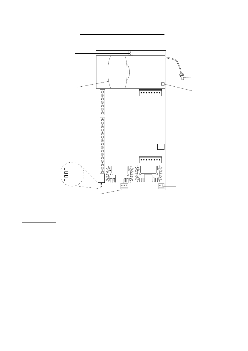
Technical Description....................................................................................4
Indicators............................................................................................................................... 4
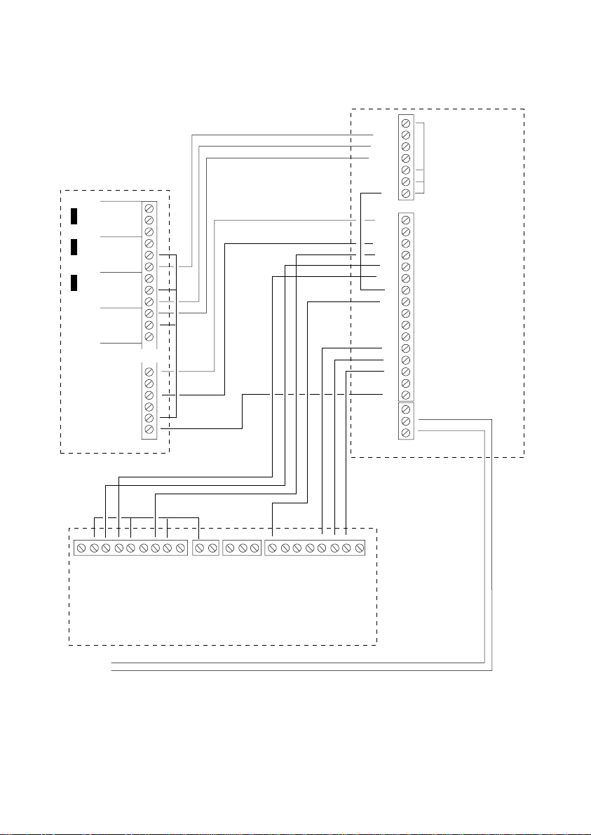
Trigger Inputs from Alarm Panel ........................................................................................... 5
Status Outputs to Alarm Panel.............................................................................................. 5
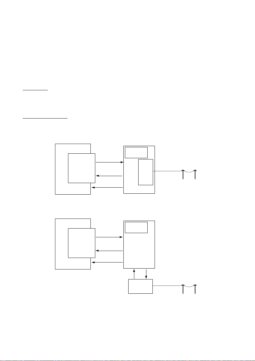
Operation............................................................................................................................... 5
Normal Alarm Operation ................................................................................................. 5
Alarm Operation with Faulty Telephone Line ................................................................. 5
Alarm Operation with Faulty GSM Link .......................................................................... 6
Alarm Operation with Both STU and GSM Faulty.......................................................... 6
Specification .......................................................................................................................... 6
Compatible Equipment.......................................................................................................... 6
Non-compatible Equipment Euro STU (Base 10) .......................................................... 6
Additional References..................................................................................................... 6
Installation ....................................................................................................7
Preparation............................................................................................................................ 7
Mains Connection ................................................................................................................. 7
Battery ................................................................................................................................... 8
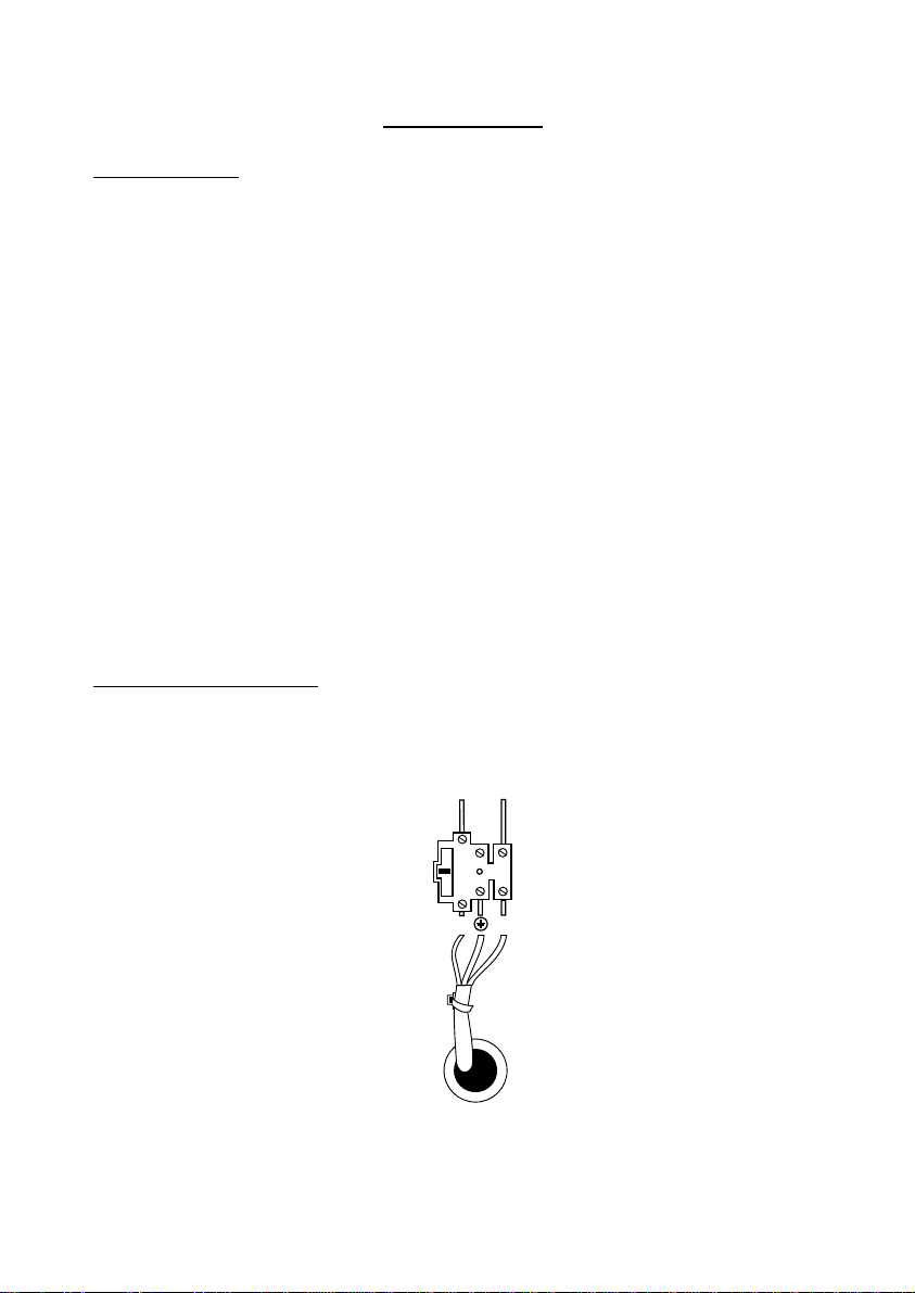
Fitting a STU ......................................................................................................................... 8
Fitting a Plug-on STU ..................................................................................................... 9
Fitting a Wire-in STU .................................................................................................... 10
Fitting a Wire-in STU (cont’d) ........................................................................................11
Return Path Signalling Connections ....................................................................................11
Programming the STU NVM ............................................................................................... 12
Completing the Installation ................................................................................................. 14
Commissioning ...........................................................................................15
Testing ........................................................................................................16
Fault Finding...............................................................................................17

496631 3
8800
Introduction
The 8800 is a remote stand alone switching unit that can connect an alarm
control panel to both the BT RedCARE alarm reporting network and to the
Cellnet: GSM network. The control panel can send alarm signals to an Alarm
Receiving Centre (ARC) over two separate paths. This ensures that signals
will get through if there are faults on either the RedCARE Network or the
GSM network.
Figure 1. Overview
The 8800 is housed in a steel case, with space for a standby battery. The
PCB provides plug-on connectors for any communicator or interface card
that conforms to the Scantronic plug-on footprint.
Figure 2. 8800 Main Components
GSM/SMS
transmitter
GSM SIM card
holder
Main connector
STU (outline)
Mains
transformer
PowerSupply
Area
7.0 Ah Battery
Space
Cellular radio
aerial

4 496631
8800
Technical Description
Sig Str
Run
Com
Figure 3. 8800 Board Layout
Indicators
The 8800 main PCB has four LEDs to show the status of the system:
Sig Str These two LEDs glow to show the strength of the GSM base
station signal received by the GSM transmitter. See “Fault
Finding” for a description of how these LEDs indicate signal
strength.
Run This LED flashes when the 8800 is operating normally.
Com This LED glows to show that the GSM transmitter is in commu-
nication with a base station.
* Transmitter LED should flash every second when GSM trans-
mitter is powered up
Main
connector
AC connector
Battery connector
Lid tamper
connector
(For factory use
only)
GSM SIM card
holder
Aerial connector
GM 22
GSM/SMS
transmitter
*Transmitter Pad
LED

496631 5
8800
Trigger Inputs from Alarm Panel
The 8800 provides 7 connectors for trigger inputs from the alarm control
panel. These are fixed as positive removed inputs.
Each input corresponds to a pin on the plug-on connector or the wire in
connector for the STU.
Status Outputs to Alarm Panel
The 8800 has two outputs that can be used to report communications status
back to the alarm control panel:
Line Fail Becomes active if the telephone line connected to the STU fails
AND the GSM signal falls below a defined level. Note that this
may take up to 30 minutes.
Tell Back Used by the ARC to remote reset the alarm control panel.
Note that RPS is used internally by the 8800.
Operation
Once an 8800 is installed and connected to an ARC the unit operates the
normal RedCARE signalling conventions using a Plug-on or Wire-in STU
connected to the PSTN. This is the primary signalling path. The 8800 uses
the GSM transmitter only if the PSTN line fails.
Normal Alarm Operation
In the event of an alarm the alarm control panel removes the +ve voltage
from its “Burg” output. The output is connected to 8800 input number 3. On
receiving +ve removed on input 3 the 8800 triggers the “Burg” input of the
STU. The STU reports the alarm to the ARC over the telephone line. The
8800 software prevents the GSM transmitter duplicating the alarm to the
ARC over the radio link.
Alarm Operation with Faulty Telephone Line
If the telephone line fails then the STU operates the “line fail” input to the
8800. The local RedCARE network scanner detects the loss of the STU and
signals “no response” to the ARC.
If an alarm occurs while the telephone line is down then the alarm control panel
triggers its “Burg” output as before. The 8800 attempts to trigger the STU. The
STU cannot report the alarm and so the 8800 triggers the GSM transmitter.
When the telephone line is restored the 8800 detects the STU being polled.
The STU clears the line fail signal to the ARC.
If there are any unrestored alarm inputs when the line restores the STU will
pass these alarms to the ARC.
Note: This is the way that RedCARE has always worked.

6 496631
8800
Alarm Operation with Faulty GSM Link
If the GSM link fails then the transmitter reports the event to the 8800. The
8800 triggers the STU to report the GSM failure on channel 8.
If an alarm occurs while the GSM link is down then the 8800 triggers the STU
to report the event over the telephone line.
Alarm Operation with Both STU and GSM Faulty
If the STU telephone line fails AND the GSM signal is lost then the 8800
activates its “Line Fail” output to the alarm control panel. This output is +12V
when active and 0V in its normal state. The Line Fail output is connected to
the alarm control panel’s “Line Fail” input. When the alarm control panel
detects the line fail signal from the 8800 then it carries out its programmed
Line Fault Response. This occurs at the point that the GSM transmitted
signal fails and the 8800 is unable to communicate. The 8800 restores the
Line Fail output only when both the STU telephone line and the GSM path
have been restored.
Specification
Dimensions h x w d 308 x 383 x 95mrn (not including
aerial)
Weight 4.6 Kg
Power 230 VAC
Inputs (communication triggers)12±2VDC, +ve removed in alarm
Outputs Voltage free relay contacts
OperatingTemperature -10° to +55°C
Compatible Equipment
3G-STU (Standalone)
3G-STU (plug-in)
BLU-STU
Scantronic Signalling Interface Cards:
9076-01/02
Non-compatible Equipment Euro STU (Base 10)
Scantronic Signalling Interface Cards:
9076-00
9075-00
Additional References
Versus Technology Limited 3GSTU Installation Guide
DA/DS Systems Universal BLU STU Installation and Programming Guide

496631 7
8800
Installation
Preparation
1. Locate the 8800 GID near the alarm control panel, in a convenient
position that allows the GSM aerial to give a clean strong signal (see
Figures 10).
2. Fit the aerial into the pre-punched hole at the top of the 8800 case.
For Panorama aerials use “Method Y” described in the fitting instruc-
tions included with the aerial.
For DTM aerials follow steps 1 to 8 in the fitting instructions included
with the aerial.
3. Connect the aerial lead to the aerial connector on the GSM Transmitter,
see Figure 3.
Note:The aerial connector is designed for ONE OFF CONNECTION ONLY. Do not
disconnect the aerial for testing or any other reason, except to replace the
aerial with a new one.
4. Power down the alarm control panel.
5. Disconnect the STU/communication device from the telephone line.
6. Remove the STU/Communication device from the alarm control panel
and put to one side (it will be needed later).
Mains Connection
The 8800 must be permanently connected to an unswitched spur outlet fitted
with a 1 Amp fuse. Connect the mains supply to the 8800 using the 3-way
terminal block located near the transformer.
To Control Panel
Transformer
315mA
N
(L)P
240Vac
Figure 4. Mains Connection
Warning: You must connect the earth lead of the mains
supply.

8 496631
8800
All electrical connections should be carried out by a qualified electrician and
must comply with the current IEEE Wiring Regulations.
When you have connected the mains lead make sure that you anchor the
cable to a suitable fixing point using a cable tie. (The steel case provides a
fixing loop near the mains connector.)
Caution: Do not apply mains power at this point.
Battery
Fit a 7.0 Ah battery in the available space within the enclosure. Do not
connect the battery at this point.
Fitting a STU
There are two ways to connect a STU: plug-on or wire-in (see Figure 5).
Plug-on STU
Wire-in STU
Control
Panel Interface or
communicator
outputs from
non-Scantronic
panel.*
Alarm signals
Control signals
Box tamper
PSTN
*Voltage free relay
output.
GSM
STU
8800
Control
Panel Interface or
communicator
outputs from
non-Scantronic
panel.*
Alarm signals
Alarm signals
Control signals
Control signals
Box tamper
PSTN
*Voltage free relay
output.
GSM
8800
Figure 5. Connecting a STU

496631 9
8800
Fitting a Plug-on STU
1. Fit the STU taken from the alarm control panel onto the 8800 communi-
cator connector.
2. Connect a multi-core alarm cable between the alarm control panel
comms outputs and the 8800 as shown in Figure 6.
To panel
anti-tamper
input
NC
C
NO
NC
C
NO
NC
C
NO
NC
C
NO
Fire
PA
Burg
CC
Line fault
Delay Override
Tellback
Not connected
12V
0V
Example:
Scantronic control panel
with plug-on 9076-02
Signalling interface card.
Note:
The mini-jumpers must be
fitted to ensure that the
relays are energised.
9076-02
Ensure that all unused
inputs are connected
to +12V
1 2 3 4 5 6 7
TRIGGER INPUTS STU
INPUTS
TAMPER
VOLTS FREE
+12V CH8 CH7 CH6 CH5 CH4 CH3 CH2CH1 0v NO NC COMLINE RPS
FAIL
TLBCK
TLBCK
RPS LINE
FAIL
CONNECT TO
PANEL INPUTS
CONNET TO
STU RELAY
OUTPUTS
Figure 6. Connecting to 8800 with Plug-on STU
Note: 1. Use cable with enough cores for each alarm trigger plus 3 return cores for
the Line Fault, RPS or Tell Back (RedCare remote reset) inputs from the 8800
to the alarm control panel. The maximum needed for all 7 alarm channels is a
12 core cable.
2. When using a plug-on 3GSTU or BLU STU with the 8800, trigger input 6
cannot be used. This should be connected to +ve as an unused input. To
output a channel 6 at the ARC with a plug-on STU connect trigger input 7.
3. To output channel 5 or channel 7 for trigger input 5 on the plug-on STU use
the mini-jumper on the 3G-STU or DIP switches 1 and 2 on the BLU-STU. See
STU installation guides for further details.

10 496631
8800
Fitting a Wire-in STU
Channel Trigger
Outputs to a
Wire-in STU
To panel
anti-tamper
input
Channel Trigger
inputs to Wire-In
STU
Outputs from STU
RPS LF CTRL
NC
C
NO
NC
C
NO
NC
C
NO
NC
C
NO
Fire
PA
Burg
CC
Line fault
Delay Override
Tellback
Not connected
12V
0V
Example:
Scantronic control panel
with plug-on 9076-02
Signalling interface card.
Note:
The mini-jumpers must be
fitted to ensure that the
relays are energised.
9076-02
8800
Ensure that all unused
inputs are connected
to +12V
Channel trigger inputs from panel
to 8800 GID (fixed at +ve removed).
1 2 3 4 5 6 7
CONNECT TO
PANEL INPUTS
CONNET TO
STU RELAY
OUTPUTS
TRIGGER INPUTS STU
INPUTS TAMPER
VOLTS FREE
+12V CH8 CH7 CH6 CH5 CH4 CH3 CH2 CH1 0v NO NC COMLINE RPS
FAIL
TLBCK
TLBCK
RPS LINE
FAIL
Note: Do not connect
terminal marked 'RPS'
to panel.
1
2
3
4
5
6
7
8
NO
C
NC
NO
C
NC
NO
C
NC
V+
0v
Versus 3G-STU 12V
Figure 7. Connecting to a Wire-in STU

496631 11
8800
Fitting a Wire-in STU (cont’d)
1. Fit the mounting plate onto the 8800 GID’s plug-on communications
connector.
2. Fit the STU taken from the alarm control panel to this plate with double
sided adhesive pads.
3. Connect the STU to the 8800 as shown in Figure 7.
Return Path Signalling Connections
All STUs need specific return path signalling connections in order to work
correctly. Figure 8 below shows these connections in detail.
ACK
LF
CTRL
0V
+12V
Note:
The ACK and LF outputs
float, then switch to zero
volts.
For older Blue STUs fit
an 8k2 pull-up resistor
between +12V and
each output.
New Blue STUs have
resistors fitted internally, and
so do not need the 8k2 resistor.
Check with D.A. which version
STU you have.
1 2 3 4 5 6 7
TRIGGER INPUTS
+12V 0vLINE RPS
FAIL
TLBCK
TLBCK
RPS LINE
FAIL
Blue STU
8800
NC
C
NO
RPS relay output.
1 2 3 4 5 6 7
TRIGGER INPUTS
+12V 0vLINE RPS
FAIL
TLBCK
TLBCK
RPS LINE
FAIL
3G-STU PLI
or
3G-STU STI
8800
CONNECT TO
PANEL INPUTS
CONNET TO
STU RELAY
OUTPUTS CONNECT TO
PANEL INPUTS
CONNET TO
STU RELAY
OUTPUTS
Figure 8. RPS Connection for STUs.

12 496631
8800
Programming the STU NVM
The STU must inform the GID when every alarm transmitted over the tel-
ephone line has been acknowledged by the Alarm Receiving Centre. The
Return Path Signaling (RPS) function carries out the acknowledgement to the
8800. To ensure that this happens you must program the STU NVM so that
all STU pins use the RPS function.
The following instructions show how to do this using a Scantronic 7200/7300
programmer.
1. Apply power to the programmer (12VDC or 12VAC).
2. Insert the master NVM into the socket marked “MASTER NVM”. Ensure
that the dot on the NVM lines up with the dot on the programmer.
3. Insert the unprogrammed NVM into the socket marked “COPY NVM”.
Ensure that the dot on the NVM lines up with the white dot on the
programmer.
4. Set the On/Off switch to position “1” and wait for the programmer to
display its version information.
5. Press YES until the display shows DUPLICATE MASTER DATA TO
COPY NVM.
6. Press YES.
The display shows: ABORT DUPLICATE
FUNCTION?
7. Press NO.
After a short delay the display shows: DUPLICATION OK
VERIFICATION OK.
8. Press YES.
The display shows: DUPLICATE MASTER
DATA TO COPY NVM
9. Press NO.
The display shows: SIMPLE 8400, 8440,
9056 PROGRAMMING.
10. Press YES.
The display shows: ACCOUNT NUMBER 1
(This is the default hard ID number.) XXXX.
11. Press NO. Enter the four figure Hard I.D.
number XXXX.

496631 13
8800
12. Press YES until the display shows: NUMBER 3 0101
Press YES if using PSTN.
OR:
Press NO if using private wire (RedDIRECT) with line monitoring, and
enter 0111.
13. Press YES until the display shows: CHANNELS TO TELE 1
XXXXXXXXX
14. Press number keys to enable all channels.
Make sure the display shows all channels: CHANNELS TO TELE 1
1 2 3 4 5 6 7 8
15. Press YES until the display shows: POSITIVE APPLIED
For a “plug on STU” program channels positive
apart from channel 4. The display should be: POSTIVE APPLIED
1 2 3 5 6 7 8
For a standalone STU, program all channels
positive removed and channel 4 positive applied.
The display should be: POSITIVE APPLIED
4
16. Press YES until the display shows: OPEN/CLOSE
17. Select all channels for signalling.
The display shows: OPEN/CLOSE
1 2 3 4 5 6 7 8
This step makes sure that all channels signal Open/Close, which is vital to the
operation of the GID unit.
18. Press YES until the displays shows: SIMPLE 8400, 8440,
9056 PROGRAMMING.
19. Set the On/Off switch to position 0 and removed the programmed NVM
from the copy socket.
20. Insert the programmed NVM into the NVM socket on the STU.

14 496631
8800
Completing the Installation
1. Re-connect the existing telephone line to the STU.
2. Refit the programmed NVM chip.
3. Fit the case tamper assembly to the lugs at the bottom of the trans-
former bracket (see Figure 9). Make sure the tamper switch is con-
nected to the tamper pins at the top of the 8800 PCB.
Figure 9. Fit Tamper Assembly

496631 15
8800
Commissioning
1. Power up the alarm control panel and enter engineer mode.
After about 30 seconds the Signal Strength LEDs will start glowing if
there is a signal present.
2. Ensure the alarm control panel communications outputs have been
connected/programmed with the correct polarity.
3. Power up the 8800, battery first and then mains.
The green Run LED should flash to show that the 8800 is operating.
4. Call the Alarm Receiving Station and request the STU to be “upped”
(see the appropriate section in the STU Installation Guide).
Note: 1. Both the STU and the GSM unit will be “upped” together.
2. If you interrupt power to the STU you will have to ask the ARC to carry out
the procedure again.
5. The GSM transmitter initialises. When the transmitter completes initiali-
zation the COM LED glows.
6. Check the radio signal strength.
The 8800 indicates signal strength as follows:
Acceptable
Unacceptable
Unacceptable
No Signal
Level 3: >8
Level 2:6 - 7
Level 1:1 - 5
Level 0
Signal Strength
Figure 10. Signal Strength Indicators
7. Fit an extension aerial cable in place of the supplied 1/4 wave stub
aerial If signal strength is low.
Note: An extension aerial cable is available from Cooper Security Ltd, Item code:
8800UK-13. Tel No. 01594 545454. This extension cable is not a signal
booster.

16 496631
8800
Testing
1. Carry out a full set of alarm reporting tests to ensure full operation.
The 8800 should send the reports out by the STU.
2. Disconnect the telephone line from the STU and carry out the alarm
reporting tests again.
The 8800 should send reports by the GSM unit.
Note: The STU continues to receive alarm inputs while the PSTN line is disconnected
and stores these events in a buffer. Although the alarms have been reported by
GSM, once you reconnect the telephone line the STU could send “duplicate”
alarm signals to the ARC as it empties its buffer. As this also happens on a
standard RedCARE connection the ARC will be expecting it.
3. When all tests are complete ensure that all connections are finalized
before leaving the site.
The alarm control panel may go into alarm when the 8800 lid tamper
operates, depending on how you have connected the tamper.

496631 17
8800
Fault Finding
Signal Strength LEDs Shows the base station signal strength received by
the GSM unit. See “Commissioning” for more
details.
Running LED Flashes on and off when the 8800 software is
running correctly.
Commissioning LED Glows steadily when the GSM unit is commis-
sioned by the service provider.

18 496631
8800
NOTES

496631 19
8800
NOTES

Cooper Security Ltd
Security House
Xerox Business Park
Mitcheldean
Gloucestershire
GL17 0SZ
Product Support (UK) Tel: (09068) 616343
Between 09:00 and 17:30 Monday to Thursday, 09:00 to 17:00 Friday
(CALLS CHARGED AT 60p PER MINUTE)
Product Support Fax: (01594) 545401
Part Number 496631 Issue 2b
Table of contents