9 / 552 Safety - general information
2 Safety - general information
2.1 Safety instructions
-
level.
DANGER
WARNING
property damage.
NOTE
property damage.
HINT
SAFETY INSTRUCTION
2.3 General safety regulations
DANGER
NOTE
O
O
SAFETY INSTRUCTION
SAFETY INSTRUCTION
O
O
WARNING
O
O
NOTE
O
O
HINT
2.3.1 Requirements for Great Britain
territory of Great Britain.
NOTE
NOTE
-
DANGER
DANGER
WARNING
2.5 Work site
.
WARNING
2.6 Handling requirements
O
O
O
O
HINT
SAFETY INSTRUCTION
device.
2.6.1 Scope of user's obligations
O
O
-
O
O
O
O
O
.
O
O
O
O
2.9 Pictograms
-
Table 2. List of pictograms placed on the device.
O
O
O
O
O
O
O
O
O
O
O
O
-
O
O
O
O
O
O
O
WARNING
NOTE
NOTE
leading to a building.
-
DANGER
NOTE
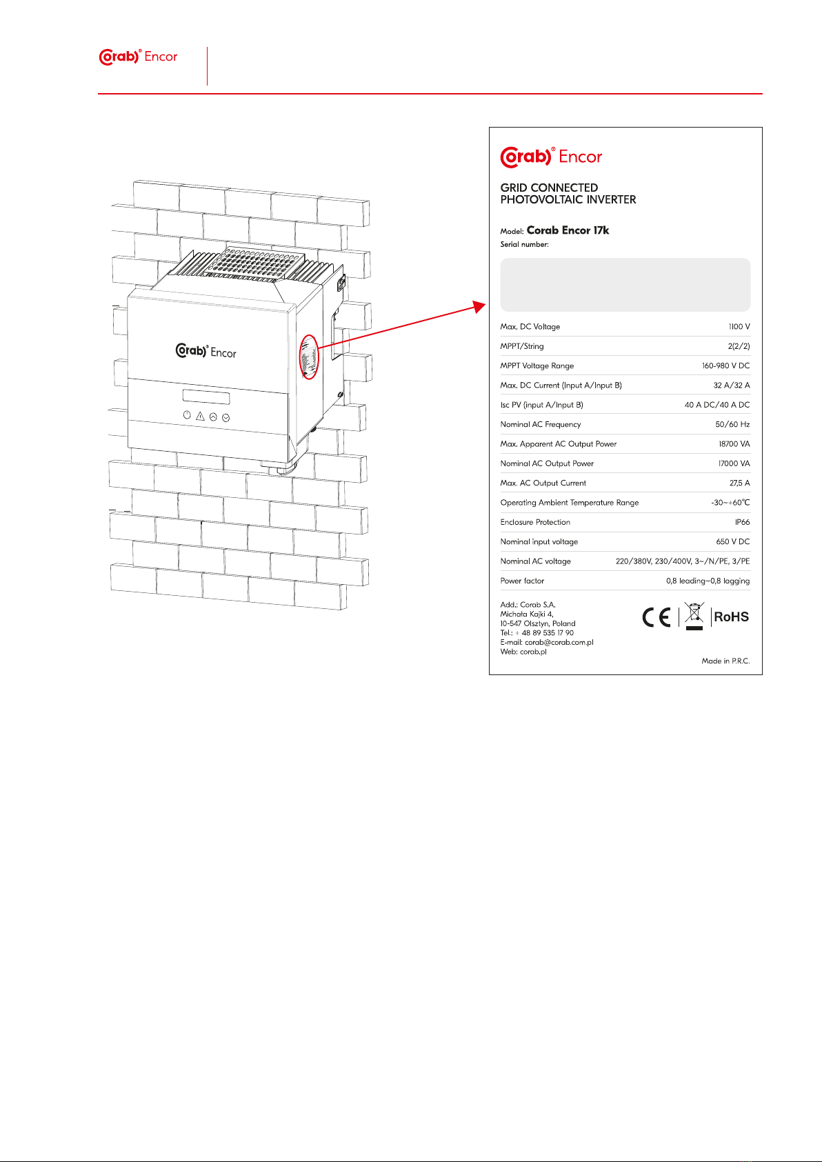
* Example of a model name
Fig. 3 Locations of pictograms on the packaging of the device.
O
O
O
in a manner against its intended purpose.
DANGER
contrary to its intended purpose.
-
O
O
O
O
O
Fig. 4 The control screen, where 1 - LED display, 2 - status diode - operation status, 3 - status diode - fault, 4 - function key – up / return,
5 - function key – down / confirm.
5.2.2 Anti-islanding
5.2.5 DC surge arrester
NOTE
NOTE
DANGER
4.4.1 Transport conditions
DANGER
unloading procedures.
4.5 Storage
C to +60
5.2.7 Arrangement of terminals and clamps
Fig. 7.
Fig. 7 Arrangement of keys and terminals on the device.
5.3.2 DC input
Table 6 DC input parameters for all models of the device.
5.3.3 AC output
Table 7 AC output parameters for all models of the device.
HINT
SAFETY INSTRUCTION
6.2.1 Tools used for assembly
Table 9 List of tools and accessories needed for the assembly of the device.
7 Starting and stopping the device
7.1 Personnel and safety
7.1.1 Results of non-compliance
O
O
O
7.2 Preparations
O
O
O
O
O
O
O
NOTE
update.
7.3 Start-up
O
O
O
DANGER
Fig 11. The prohibited installation method.
6.4.1 Place of installation
O
O
O
O
O
DANGER
Fig. 12 Position of the device after installation.
8.2.1 Functions diagram
Fig. 11 cos ф=f(P) setting for the VDE ARN 4105 standard.
-
Fig. 12 cos ф=f(P) setting for the E8001 standard.
Fig. 13 The standard curve for passive power Q=f(V), where V2s= 1.10Vn, V1s=1.08Vn=QuVlowRate, V2i=0.90Vn, V2i=0.92Vn= QuVlowRate.
8.2.8 Parameter: Grid protection
8.2.11 Parameter: Advanced settings
Table 13 Adv. settings parameters.
8.2.12 Function: Information
-
Table 14 Information function.
O
O
O
O
O
O
O
.
2.7 Personal protective equipment
O
O
O
O
O
O
safety belts.
-
O
O
O
O
O
HINT
O
O
O
O
O
DANGER
NOTE
HINT
O
use proper personal protective equipment;
O
avoid contact with the top and the back part of the inverter - components which heat up;
O
replace pictograms (section 2.9 of this manual), which inform about hot surfaces whenever they become dama-
ged, illegible or removed.
O
follow the requirements of the PV module manufacturer within the scope of safety and possible hazards;
O
install the device at a site with proper air circulation;
O
the place of installation must not expose the device to direct exposure to sunlight and/or weather conditions.
O
:
O
Fig. 2 Location of pictograms on the device.
Table 3. List of pictograms placed on the packaging of the device.
3 Rules of use
O
O
O
O
O
O
features anti-islanding.
-
C to
+60
.
HINT
O
O
O
O
O
O
O
O
O
O
O
oC to +60o
above 45o
O
O
O
O
O
O
O
5 Construction
5.1 Personnel and safety
5.1.1 Results of non-compliance
O
O
O
5.2 Inverter - construction
5.2.1 Control panel
in Table 4 and marked in Figure 4:
Table 4 Elements of the control panel.
4 Transport and storage
4.1 Personnel and safety
4.1.1 Results of non-compliance
O
O
O
4.2 Preparations
-
DANGER
HINT
personnel.
Manufacturer - Corab S.A.
4.2.1 Packing
4.3 Package marking
4.4 Transport
5.2.6 Communication interface
O
O
O
Fig. 5 Communication between a computer and the inverter through RS-485.
O
Fig. 6 Diagram for data transmission with the use of a meter.
O
O
5.3.1 General details
Table 5 List of general details of all models of the device.
Fig. 8 Marking of device dimension.
Fig. 9 Chart depicting the change in working parameters for Corab Encor 17k depending on temperature.
6 Assembly
6.1 Personnel and safety
6.1.1 Results of non-compliance
O
O
O
6.2 Procedures and tests
DANGER
-
O
O
O
O
O
O
O
O
O
O
O
O
DANGER
WARNING
WARNING
WARNING
NOTE
SAFETY INSTRUCTION
6.5 Commissioning
O
O
DANGER
2014/30/EU may lead to a dangerous situation.
O
O
NOTE
O
SAFETY INSTRUCTION
Table 8 Parameters of protective equipment and eectiveness for all models of the device.
5.4 Operating modes
O
O
O
O
-
ter
6.3 Additional elements
requires a particular element.
DANGER
regulations and standards.
6.4 Installation
-
elements and assembly.
DANGER
performed task.
Fig. 10 Installation diagram.
8 Operation
8.1 Personnel and safety
8.1.1 Results of non-compliance
O
O
O
8.2 Functions and operation
-
O
O
-
O
O
O
O
O
O
-
O
8.2.6 Parameter: Exp. control
and Meter direction options.
8.2.2 Function: Status
O
O
PV – stands for current electrical data for PV modules.
Table 10 Parameters of the Status function.
8.2.3 Function: Meter
8.2.4 Functions: Log
8.2.5 Function: settings
Password: 0000
Access
password: 2014
O
O
O
O
O
Table 11. Parameters for grid protection: voltage, frequency, voltage range, curve par.
8.2.9 Parameter: Monitoring
Table 12 Monitoring parameters.
8.2.10 Parameter: System reset
7.4 Restart
O
O
WARNING
O
O
O
DANGER
O
O
O
NOTE
O
O
O
NOTE
O
O
O
O
O
O
DANGER
DANGER
operation of a damaged device may lead to a dangerous situation.
O
O
O
WARNING
situation.
HINT
O
DANGER
NOTE
61730- 1:2018-06.
8.3 Failures
DANGER
NOTE
HINT
8.3.1 Procedure in case of failures
Table 15 Test parameters.
8.3.2 Servicing Department - contact
manual.
DANGER
8.4 Update
Fig. 16 Wi-Fi port.
NOTE
update\ARM\618.xxxxx.00_MICPROG2_ARM_Vx.xx_xxxxxxxx.usb
update\DSP\618.xxxxx.00_MICPROG2_DSP_Vx.xx_ xxxxxxxx.usb
Vx.xx – version number
HINT
NOTE