CORNING Centrix User manual
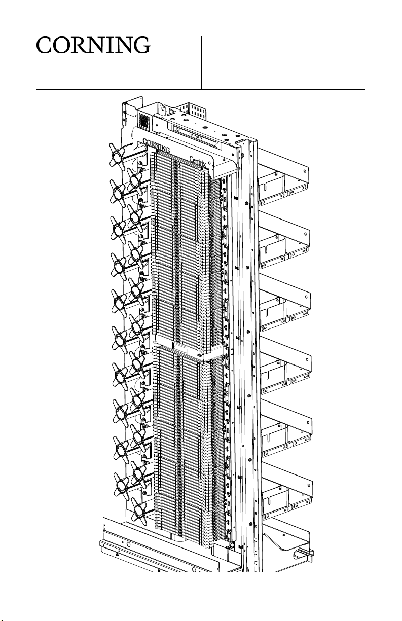
p/n 003-960, Issue 4
Jumper Routing in
Centrix™ System Frame
TPA-5743


p/n 003-960, Issue 4
STANDARD RECOMMENDED PROCEDURE 003-960 | ISSUE 4 | OCTOBER 2017 | PAGE 1 OF 18
Jumper Routing in
Centrix™ System Frame
related literature |
003-948 Centrix System Housing Installation
003-949 Centrix System Pigtailed Housing with Pigtailed Cassette
Installation
003-950 Centrix System Frame Installation
003-951 Centrix System Stubbed Housing Installation
003-959 Centrix System Splitter/CWDM Cassette Installation
003-961 Centrix System Accessories Installation
Table of Contents
1. Connect Jumpers .......................................... 2
2. Jumper Routing and Slack Storage when Cross-connecting
in the Same Frame ......................................... 5
2.1. Connecting Housing 1 to Housing 6 ...................... 5
2.2. Connecting Housing 5 to Housing 6 ...................... 6
2.3. Connecting Housing 1 to Housing 10 ..................... 7
2.4. Full Frame Composite Cross-connect Routing .............. 8
3. Cross-connecting Jumpers in Adjacent Frames ................... 9
3.1. Cross-connecting Jumpers in Adjacent Rear
Cable Access Frames ................................. 9
3.2. Cross-connecting Jumpers in Adjacent Front
Cable Access Frames ................................ 10
4. Cross-connecting Jumpers Using Overhead Trough System........ 11
5. Jumper Routing and Slack Storage when Interconnecting
between Frames.......................................... 12
5.1. Initial Jumper Routing from Source Frame ................ 12
5.2. Subsequent Jumper Routing from Source Frame ........... 13
5.3. Interconnecting to Active Equipment ..................... 14
5.4. Interconnecting Jumper Routing to Active Shelves in a
Different Frame Lineup Using Overhead Trough System ..... 16
5.5. Interconnecting Jumpers between Distantly Spaced Ports .... 17
6. Connector Care and Cleaning ............................... 18
STANDARD RECOMMENDED PROCEDURE 003-960 | ISSUE 4 | OCTOBER 2017 | PAGE 2 OF 18
1. Connect Jumpers
WARNING: Never look directly into the end of a ber that may be
carrying laser light. Laser light can be invisible and can damage your
eyes. Viewing it directly does not cause pain. The iris of the eye will
not close involuntarily as when viewing a bright light. Consequently,
serious damage to the retina of the eye is possible. Should accidental
eye exposure to laser light be suspected, arrange for an eye
examination immediately.
• Make the connections in the rst cassette as described in this section.
• Then route the jumpers as described in Section 2 or 5for your application.
• Lastly, make the connections in the second cassette following the
instructions in this section.
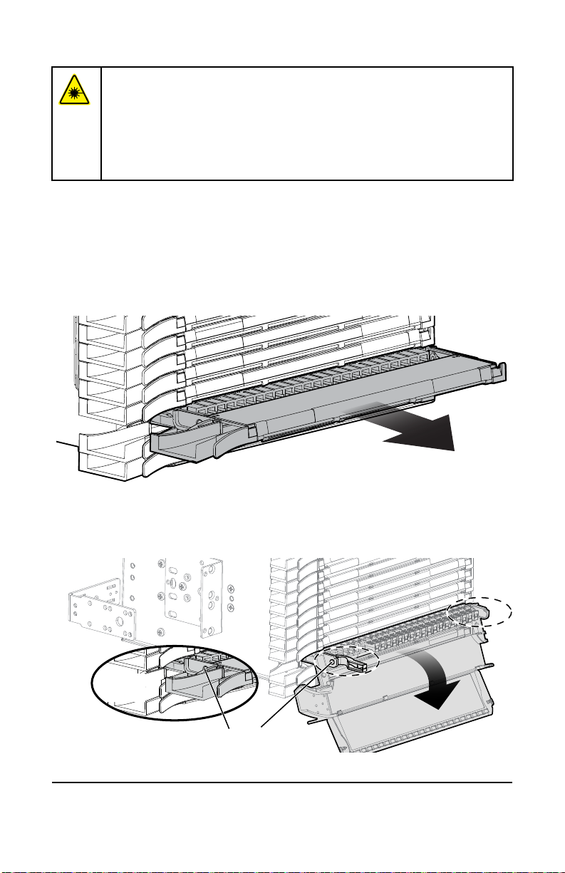
Step 1: If routing jumpers to an adjacent frame, start with the most densely
loaded frame (source frame). Pull module out to detent position
(Figure 1).
Figure 1
Step 2: Press buttons on each side of the cassette (Figure 2) and lower the
handle.
Figure 2
TPA-4460
TPA-4461
Press
buttons
STANDARD RECOMMENDED PROCEDURE 003-960 | ISSUE 4 | OCTOBER 2017 | PAGE 3 OF 18
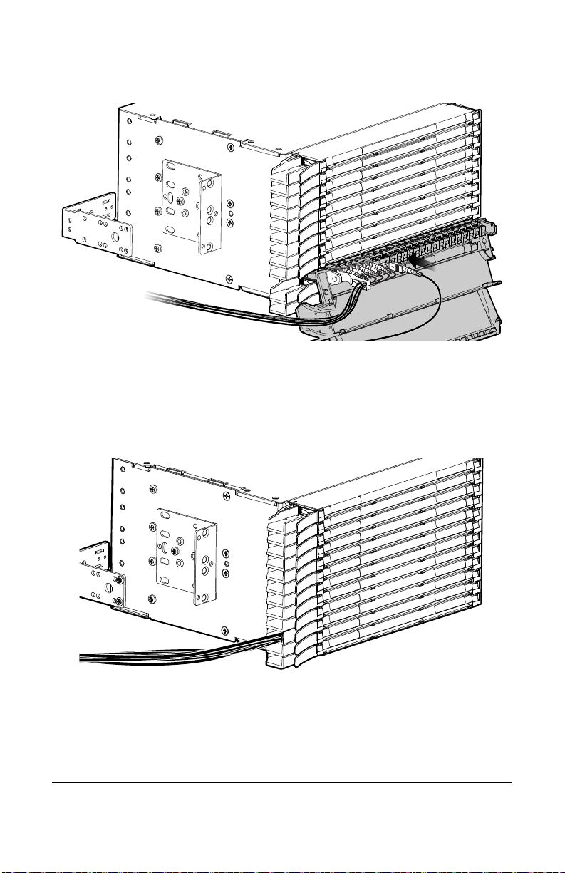
Step 3: Remove dust caps and clean adapters and connectors per
standard company practices or as described in Section 6. Connect
jumpers as required (Figure 3).
Figure 3
Step 4: Dress jumpers under the aps on the handle and out the left side of
the cassette (Figure 3).
Step 5: Then raise the handle until the buttons on each side engage to hold
the handle up (Figure 4).
Step 6: Lastly, close the cover over the jumper cables.
Figure 4
TPA-4462
TPA-4463

STANDARD RECOMMENDED PROCEDURE 003-960 | ISSUE 4 | OCTOBER 2017 | PAGE 4 OF 18
This page intentionally left blank.

STANDARD RECOMMENDED PROCEDURE 003-960 | ISSUE 4 | OCTOBER 2017 | PAGE 5 OF 18
2. Jumper Routing and Slack Storage when Cross-
connecting in the Same Frame
When cross-connecting jumpers within one frame, use a single-ber
jumper length of 4 m (13 ft) to eliminate the need to cut jumpers to a
specic length.
• Determine location of jumper termination.
• Connect both ends of the jumpers to the selected adapters, then route
slack under both transition spools and over the highest hub that can
be reached without pulling on the jumper.
• If the termination is within the same frame, refer to Figure 5. If the
jumper termination is within another frame, skip to Section 5.
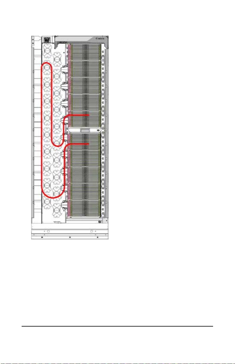
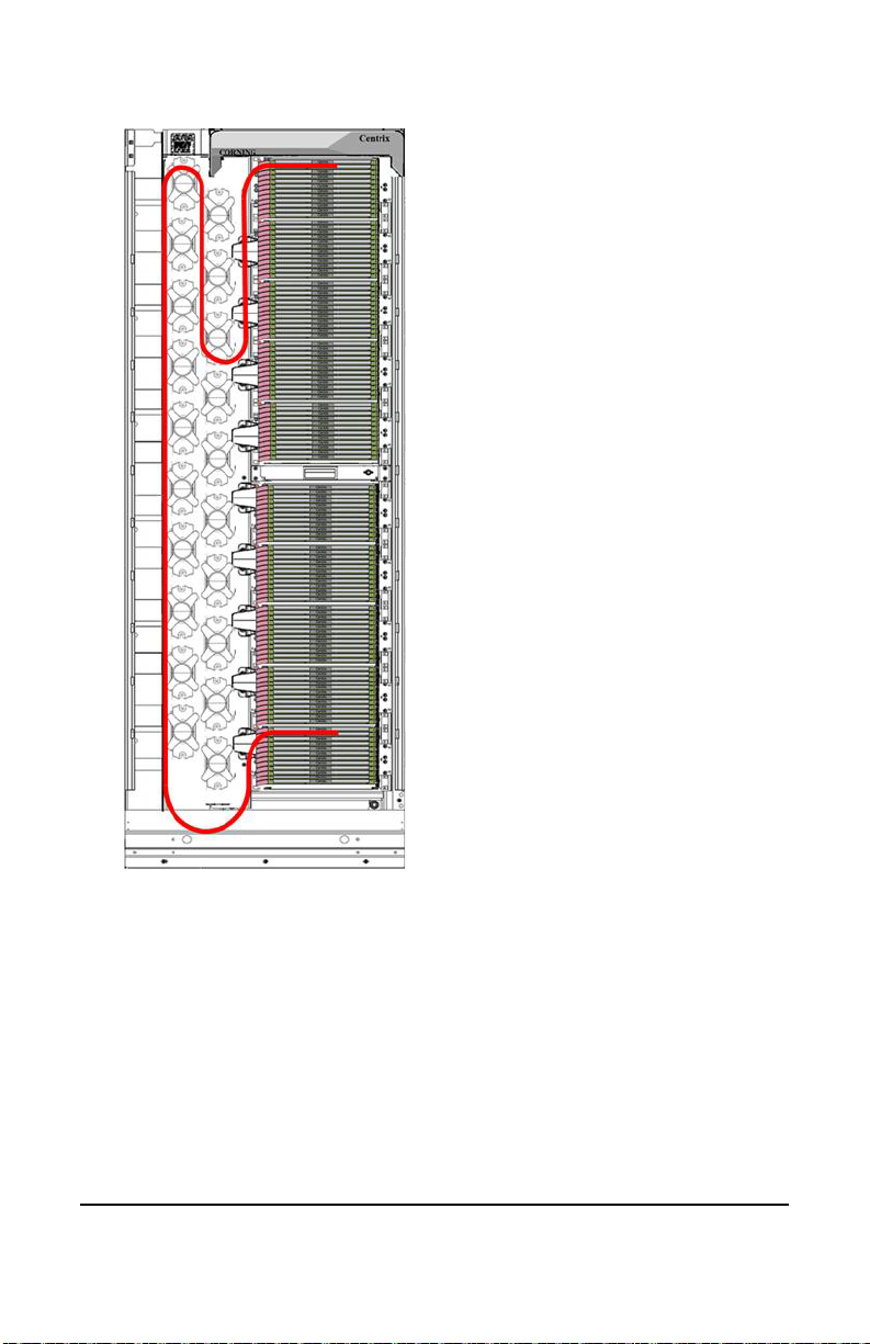
2.1. Connecting Housing 1 to Housing 6
Figure 5
TPA-4450
bottom five housings assigned
to outside plant (OSP)
Unless noted other-
wise, jumper routing
configurations
are the same for
front and rear
cable access frames.
Cross-connecting
in the same frame
Top five housings assigned
to active equipment (EQ)
Connecting housing 1
to housing 6
STANDARD RECOMMENDED PROCEDURE 003-960 | ISSUE 4 | OCTOBER 2017 | PAGE 6 OF 18
2.2. Connecting Housing 5 to Housing 6
Figure 6
TPA-4453
Cross-connecting
in the same frame
Connecting housing 5 to housing 6
STANDARD RECOMMENDED PROCEDURE 003-960 | ISSUE 4 | OCTOBER 2017 | PAGE 7 OF 18
2.3. Connecting Housing 1 to Housing 10
Figure 7
TPA-4452
Cross-connecting
in the same frame
Connecting housing 1 to housing 10
STANDARD RECOMMENDED PROCEDURE 003-960 | ISSUE 4 | OCTOBER 2017 | PAGE 8 OF 18
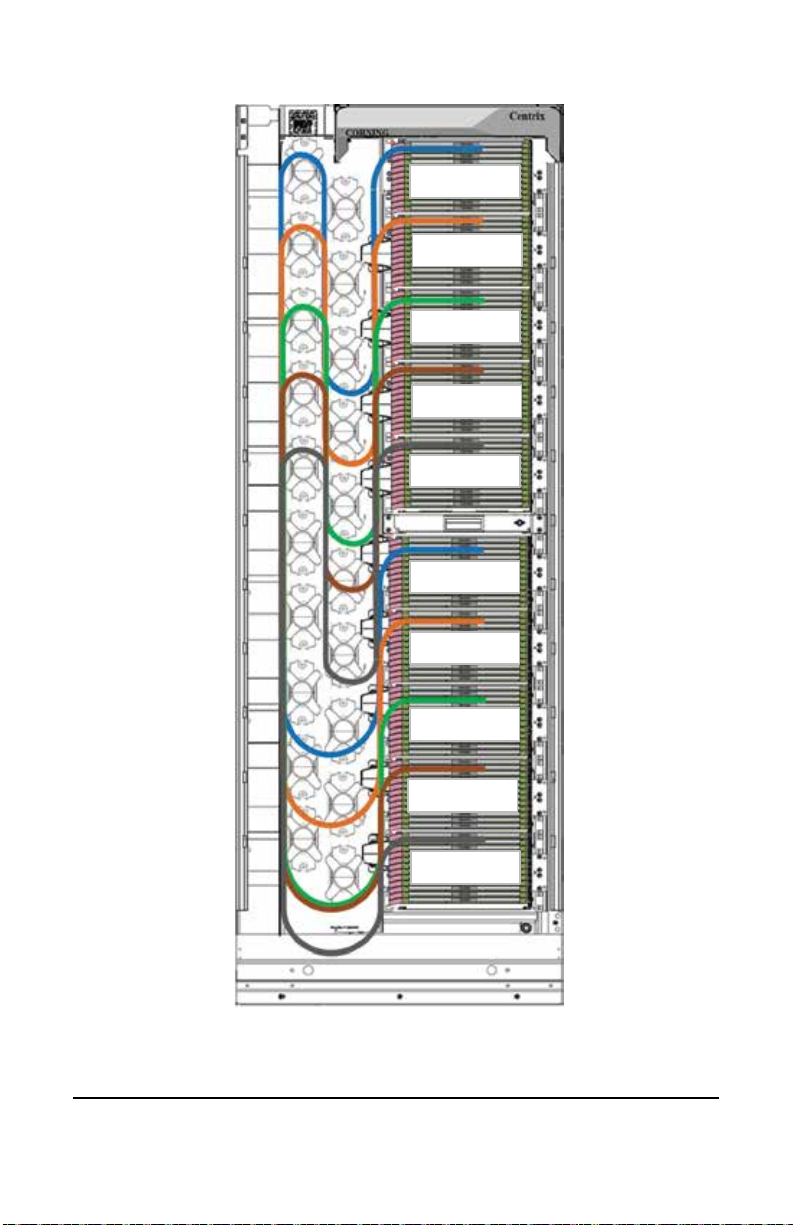
2.4. Full Frame Composite Cross-connect Routing
Figure 8
TPA-4568
EQ # 1
EQ # 2
EQ # 3
EQ # 4
EQ # 5
OSP # 1
OSP # 2
OSP # 3
OSP # 4
OSP # 5
Other manuals for Centrix
3
Table of contents
Other CORNING Accessories manuals


