corob CLEVERmix 700 User manual

TM - V1.0R0 (05/2017)CODE - EVD
TECHNICAL MANUAL
COROB™ CLEVERmix 700
Gyroscopic Mixer with MINIEMIX Electronics

TECHNICAL MANUAL
Gyroscopic Mixer
COROB™ CLEVERmix 700
Version 1.0 - R0 (05/2017)
© COPYRIGHT 2017, COROB S.p.A.
All rights reserved in all countries.
If you require additional copies of this manual or further technical information about it, please write to:
COROB S.p.A.
Via Agricoltura 103 • 41038 San Felice s/P • Modena • Italy
Phone: +39-0535-663111 • Fax: +39-0535-663285
www.corob.com
INTELLECTUAL PROPERTY RIGHTS AND DISCLAIMER
No part of this manual may be translated into any other languages and/or adapted and/or reproduced in any form, or by any means, electronic or me-
chanical, including but not limited to photocopying and recording, without prior written permission of COROB S.p.A.
COROB™ is a registered trademark and/or commercial trademark used on an exclusive basis by COROB S.p.A. and its aliated companies (hereinafter
“COROB”).
A failure of a trademark to appear hereunder does not mean that COROB does not use the trademark in question nor does it constitute a waiver by
COROB of any related intellectual property rights.
Valuable proprietary technical information contained in the present manual are referring to proprietary know-how, designs, drawings and/or applica-
tions used on an exclusive basis by COROB frequently covered by Patents and/or Patent Applications and thus protected by International and National
Intellectual Property Laws.
Unless otherwise indicated, all references to other companies other than COROB and its aliated companies, their names, data and addresses used in
the screens and/or examples are purely coincidental and serve as a reference only to clarify the use of the COROB™ products.
COROB has carefully reviewed the wording and imagines contained in the present manual, nevertheless COROB reserves the right to modify and/or
update the information herein to correct editorial errors and/or inaccuracy of the information herein without notice or commitment on its part.
The manual contains guidelines and/or information for product repair. For safety reasons, only trained and authorized technical personnel should per-
form such interventions.
Authorized technical personnel shall mean technicians who have attended a technical training course held by COROB and/or its aliated companies.
Unauthorized interventions could void the warranty coverage of your COROB™ product pursuant to the sales contract or to the General Sales Conditions
of COROB. COROB can be held responsible only within the limits of the warranty coverage provided by the General Sales Conditions.
COROB does not intend to limit or exclude its liability against any statutory provisions under any applicable law. Therefore the reference to above war-
ranty limitations or exclusions may not apply.

TABLE OF CONTENTS - iii
COROB™ CLEVERmix 700
TABLE OF CONTENTS
1 GENERAL INFORMATION AND SAFETY..................................................................................................................................... 7
1.1 Purpose and structure of the manual................................................................................................................................................................ 7
1.2 Intended user of this manual ............................................................................................................................................................................... 7
1.3 Symbols........................................................................................................................................................................................................................ 8
1.4 General safety guidelines....................................................................................................................................................................................... 8
1.5 Residual risks ............................................................................................................................................................................................................10
1.6 Safety devices...........................................................................................................................................................................................................11
1.7 Emergency stop.......................................................................................................................................................................................................12
1.8 Tools.............................................................................................................................................................................................................................12
2 INFORMATION AND TECHNICAL FEATURES........................................................................................................................... 15
2.1 Description of the machine.................................................................................................................................................................................15
2.2 Standard control panel conguration.............................................................................................................................................................15
2.3 Performance and features ...................................................................................................................................................................................16
2.4 Technical data ..........................................................................................................................................................................................................16
2.5 Dimensions and weight........................................................................................................................................................................................17
3 INSTALLATION ........................................................................................................................................................................... 21
3.1 Requirements of the installation site...............................................................................................................................................................21
3.2 Unpacking and positioning ................................................................................................................................................................................21
3.3 Electrical connection and start-up ...................................................................................................................................................................23
3.3.1 Machine information ....................................................................................................................................................................... 23
4 CONTROL ELECTRONICS........................................................................................................................................................... 27
4.1 Introduction..............................................................................................................................................................................................................27
4.2 MINIEMIX board position.....................................................................................................................................................................................27
4.3 Power supply voltage distribution ...................................................................................................................................................................28
4.4 MINIEMIX board layout.........................................................................................................................................................................................29
4.4.1 Connectors.......................................................................................................................................................................................... 30
4.4.2 LEDs ...................................................................................................................................................................................................... 31
4.4.3 Dipswitch settings............................................................................................................................................................................. 32
5 CONTROL PANEL AND CONFIGURATION................................................................................................................................ 35
5.1 Control panel functions........................................................................................................................................................................................35
5.2 Machine parameters conguration..................................................................................................................................................................36
5.2.1 Parameter grid ................................................................................................................................................................................... 37
5.2.2 Control panel keys............................................................................................................................................................................. 38
5.2.3 Entering parameter edit mode....................................................................................................................................................... 38
5.2.4 Language ............................................................................................................................................................................................ 38
5.2.5 Editing parameters ........................................................................................................................................................................... 39
5.2.6 Exit without saving ........................................................................................................................................................................... 39
5.2.7 Save & Exit........................................................................................................................................................................................... 39
5.2.8 Mixing speed (AUTO)........................................................................................................................................................................ 40
5.2.9 Mixing time (AUTO)........................................................................................................................................................................... 40
5.2.10 Clamping force adjustment (AUTO) ............................................................................................................................................. 41
5.2.11 Mixing speed limits (MANUAL)....................................................................................................................................................... 42
5.2.12 Mixing time limits (MANUAL)......................................................................................................................................................... 42
5.2.13 Clamping plate re-opening ............................................................................................................................................................ 42
5.2.14 Restore conguration....................................................................................................................................................................... 43
5.2.15 Factory reset ....................................................................................................................................................................................... 43
6 HARDWARE ERRORS.................................................................................................................................................................. 47
6.1 Introduction..............................................................................................................................................................................................................47
6.2 Errors and warning messages ............................................................................................................................................................................47

iv - TABLE OF CONTENTS
COROB™ CLEVERmix 700
7 MAINTENANCE........................................................................................................................................................................... 53
7.1 Introduction..............................................................................................................................................................................................................53
7.2 Technical intervention check-list ......................................................................................................................................................................53
7.3 Lubrication points...................................................................................................................................................................................................54
7.4 Guards and panels disassembly ........................................................................................................................................................................55
7.5 Door.............................................................................................................................................................................................................................56
7.5.1 Cleaning and lubrication ................................................................................................................................................................ 56
7.5.2 Disassembly and reassembly ......................................................................................................................................................... 56
7.6 Mixing motor............................................................................................................................................................................................................57
7.6.1 Disassembly and replacement....................................................................................................................................................... 57
7.6.2 Belt replacement and tensioning.................................................................................................................................................. 57
7.7 Clamping motor......................................................................................................................................................................................................58
7.8 Repositioning pin motor......................................................................................................................................................................................60
7.9 Sensors........................................................................................................................................................................................................................61
7.10 Door safety device..................................................................................................................................................................................................62
7.10.1 Disassembly / Assembly / Replacement ...................................................................................................................................... 62
7.11 Inverter .......................................................................................................................................................................................................................63
7.11.1 Disassembly / Assembly / Replacement ...................................................................................................................................... 63
7.12 Power Supply Unit..................................................................................................................................................................................................64
7.12.1 Disassembly / Assembly / Replacement ...................................................................................................................................... 64
Appendix: Electrical Technical File

GENERAL INFORMATION AND SAFETY
1

BLANK PAGE
COROB™ CLEVERmix 700

GENERAL INFORMATION AND SAFETY - 7
COROB™ CLEVERmix 700
1 GENERAL INFORMATION AND SAFETY
1.1 Purpose and structure of the manual
This manual, prepared by the manufacturer, contains technical information for the installation of the machine and provides technical
documentation regarding machine electronics, mechanics, rmware and hardware errors.The technical manual is divided into sections.
The following topics are handled:
SECTION 01 GENERAL INFORMATION AND SAFETY SECTION 05 CONTROL PANEL AND CONFIGURATION
SECTION 02 INFORMATION AND TECHNICAL FEATURES SECTION 06 HARDWARE ERRORS
SECTION 03 INSTALLATION SECTION 07 MAINTENANCE
SECTION 04 CONTROL ELECTRONICS SECTION 08 WIRING DIAGRAMS
Changes may have been made to the product to improve its performance after this technical manual was printed. Accordingly, the
manufacturer does not warrant that the information contained in this manual is complete and accurate.
1.2 Intended user of this manual
The manual is aimed as a supportive tool to service providers with specic skills and technical competence (mechanical and electrical)
and qualied as COROB Authorized Service Providers, trained by COROB in order to carry out installation, service and maintenance of
COROB™ equipment.Therefore, the information contained in this manual shall be considered as a guideline only and must be supported
by a COROB Technical Training and a formal authorization as COROB Authorized Service Provider. COROB recommends to follow the
procedures described in this manual. Service interventions other than those stated and suggested herein are not recommendable
and must be considered performed under the own responsibility of the Service Provider. COROB disclaims any liability for personal or
property damages resulting from failure to observe the instructions given and safety guidelines provided in this manual.
IMPORTANT NOTE
At the time of publishing this edition of the manual COROB has used its best eorts to ensure that the information contained herein
is complete and accurate. Notwithstanding, pursuant to product development and technical innovation over time, COROB may
have introduced changes and/or revisions to COROB™ products after the date of publishing this edition. Please contact COROB to
obtain the most recent version of the manual.

8 - GENERAL INFORMATION AND SAFETY
COROB™ CLEVERmix 700
1.3 Symbols
The symbols used in this manual, in order to facilitate understanding and to highlight risky operations, are shown and described below.
Safety symbols Equipment symbols
DANGER
Indicates information or procedures that, if not strictly
followed can cause serious injuries to the operator or
damage to the machine.
MECHANICAL TOOLS
Indicates that for the work to be done the use of tools is
required.
PROHIBITED
Signals an action that is not allowed.
LIFTING EQUIPMENT
Indicates that for the work to be done the use of lifting
equipment is required.
COMPULSORY
Signals compulsory actions or procedures.
ELECTRICAL TOOLS
Indicates that for the work to be done the use of electrical
tools is required.
NOTE
Indicates important instructions referring to
precautionary rules and/or measures to adopt.
MANAGEMENT COMPUTER
Indicates that for the work to be done the use of the
management computer is required.
PERSONAL PROTECTIVE EQUIPMENT
Indicates that personnel in charge of the operations
described must wear the personal protective equipment
indicated.
1.4 General safety guidelines
READ THE SAFETY WARNINGS CAREFULLY BEFORE INSTALLING AND OPERATING WITH THE MACHINE.
• ALWAYS PLUG THE MACHINE INTO A SOCKET THAT ENSURES PROPER GROUNDING. The line must be protected from overloads,
short-circuits and direct contacts according to current accident prevention regulations. Incorrect grounding may lead to the risk of
electrical shock.
• The machine must not be powered by a power source having specications other than those listed on the identication plate.
• The machine is isolated from the power supply line when the power plug is disconnected; it must therefore be installed near an easily
accessible mains socket outlet.
• Do not use extension cords to power the machine.
• Do not use multisockets to connect other equipment to the same socket that powers the machine. Make sure that the power supply of the
equipment connected to the machine via serial port, like the computer, is equipotential (which has a single access point to earth) because
potential dierences cause interferences and/or damage to the serial ports.
• Periodically check the condition of the power supply cable; if it is damaged, replace it with a new cable supplied by the manufacturer.
• To prevent any risk of electrical shock or injuries, use the machine indoors only. It is prohibited to use the machine outdoors where it could
be subjected to rain or high humidity.
• The machine must be used only for its intended purpose.
• Pay close attention to the signs on the machine.
• It is strictly forbidden to use the machine without protections or with any safety devices present on the machine disabled, broken
down, or removed. The panels must be kept closed at all times.
• It is forbidden to use cans having characteristics other than those stated in this manual.
• It is forbidden to use the clamping movement of plates to close the can lid.
• It is forbidden to climb onto the bottom clamping plate and/or onto any other parts of the machine.
• It is forbidden to use the machine as a working surface; it is also prohibited to leave objects on the machine during while it’is operating.
• Always unplug the power supply cable from the socket outlet before carrying out any maintenance operations.

GENERAL INFORMATION AND SAFETY - 9
COROB™ CLEVERmix 700
• Prior to carrying out any repair intervention, adopt suitable safety measures in compliance with safety in the work place legislation in force
and follow safety instructions.
• When prescribed, wear personal protective equipment.
• Do not carry out any interventions on the machine when it is electrically powered, unless otherwise indicated.
• After every repair intervention reassemble the guards.
• In the event of a breakdown on any of the electronic control equipment, replace the damaged equipment immediately; do not attempt
to repair the breakdown.
• Use only original spare parts for replacement.
• Do not operate the broken down or damaged machine.
• The machine is suitable for use with tinting products in general. Scrupulously follow the safety precautions and the instructions for use
given on the colorant package and on the Material Safety Data Sheet (MSDS) supplied by the manufacturer. When compulsory, wear
personal protective equipment.
• THE MACHINE IS NOT EXPLOSION-PROOF AND MUST NOT BE USED IN CLASSIFIED AREAS (AREAS AT RISK FOR EXPLOSION).
• The substances that may be used on the machine--such as colorants, paints, solvents, lubricants and cleansers--may be hazardous to your
health; handle, store and dispose of these substances in keeping with current regulations and the instructions provided with the product.

10 - GENERAL INFORMATION AND SAFETY
COROB™ CLEVERmix 700
1.5 Residual risks
Risk Preventive measure P. P. E .
Risk of electrocution - Risk of electrical shock
if you power the machine from a socket not
equipped with ground connection.
Power the machine through a grounded socket outlet.
\
Risk of electrocution / burning - Risk of electrical
shock if you access machine parts protected by
panels without rst cutting o electrical power.
The operator is not authorized to access the machine
parts protected by panels.
For the maintenance technician: before performing
any maintenance intervention, shut o the machine
and disconnect the power supply cable from the mains
socket outlet.
Wait for some minutes before touching the motor.
\
Dorsal/lumbar injuries - Handling heavy loads
when moving the machine and loading cans in
the machine may cause injuries.
Do not exceed the weight limits stated by the current
regulations in force (20 kg/44 lb for women, 25 kg/55
lb for men).
Use appropriate lifting equipment or provide for two
operators to carry out the task.
Risk of slipping / falling - Improper use of the
bottom clamping plate (for example, climbing on
the plate to take items from high shelves above
the machine) can cause injuries.
It is forbidden to climb onto the bottom clamping plate
and/or onto any other parts of the machine. \
Risk of falling objects / crushing - When
loading a can in the machine, there is a risk it may
fall onto the operator. During machine operation,
any objects left on the machine may fall onto the
operator.
Position the can so that the whole base rests on the
bottom clamping plate.
Do not exceed the maximum weight allowed for the can
or cans to be mixed.
Do not use the machine as a working surface. Do not
leave any objects on the machine during its operation.
Risk of cuts - Risk of injuries and abrasions
caused by sharp edges and end parts of the cans
to be handled.
Wear appropriate personal protective equipment (cut-
proof gloves).
Do not use the machine with damaged cans or cans not
sealed properly.
Risk of explosion - Fumes generated by the
colorants used may cause an explosion.
Do not use the machine in classied areas (areas at risk
for explosion).
Avoid naked ames or material that may create sparks
and cause a re.
\
Risk of poisoning and sensitization
Eye and skin contacts and inhalation of vapors/
powders caused by product spills from the can
being broken.
Fumes generated by the colorants used may
cause poisoning and/or sensitization during
machine cleaning and disposal operations.
Do not use the machine with damaged cans or cans not
sealed properly.
Read the warnings reported in the Material Safety
Data Sheets of the colorants used. The MSDS must be
provided by the colorant manufacturer.
Keep the room suitably ventilated.
Wear appropriate personal protective equipment
(safety goggles, gloves and mask).
Personal
Protective
Equipment
as specied
in MSDS.
Risk of crushing / entanglement / dragging
/ abrasion / cutting - During extraordinary
maintenance interventions.
Before carrying out any maintenance operations, you
must turn o the machine and unplug the power
supply cable from the mains socket outlet.
Risk of burning due to contact with hot
surfaces - During maintenance operations of
the mixing motor.
During normal use, the machine mixing motor works
in a non-continuous way, considering the paint can
loading and unloading time.
If operated at full charge, with the maximum load
allowed (35 kg/77 lb) at highest ambient temperature
value (40°C), there could be motor overheating risks.
As a preventive measure, ALWAYS wait at least 30
minutes after the last working cycle has ended, before
touching the mixing motor to carry out maintenance
interventions. The motor is protected by a safety guard
and cannot be reached by the machine operator
normally.

GENERAL INFORMATION AND SAFETY - 11
COROB™ CLEVERmix 700
1.6 Safety devices
Emergency button
Red mushroom-head button.
Pressing the button causes the machine to stop immediately in emergency mode, ceasing all movements.
Once pressed, the button can be released by pulling it outward.
Door safety device
The machine is equipped with a door safety device that:
• prevents the mixing cycle to be started when the door is open
• keeps the door locked during mixing of the can
During the mixing cycle, the door can only be opened if the mixing mechanics is in vertical position, i.e. when the can is clamped or
released. Opening the door in these cases causes all movements to be immediately stopped, for obvious safety reasons.
Door lock
As an optional device, a door lock system can be requested: it prevents door opening at any time of the cycle. With this option, it will
not be possible to open the door, neither during plate closing (clamping of the can) nor during plate opening (release of the can).

12 - GENERAL INFORMATION AND SAFETY
COROB™ CLEVERmix 700
1.7 Emergency stop
In case of a breakdown or dangerous conditions, press the emergency stop button. Pressing this button, power is cut o to the entire
machine and all movements are stopped.
The display will show a message that indicates the emergency stop condition. After eliminating the cause of the malfunction or solved
the dangerous condition, reset the button by pulling it.
DANGER
The emergency button does not completely cut o power to the entire machine. The power supply unit box inside the machine still
remains powered.
To completely remove power from the machine it is necessary to shut it o and unplug the power supply cable from the wall socket
outlet.
The use of the emergency stop button is to be considered as an emergency action exclusively, and not as a standard stop mode, in
order to prevent machine deterioration.
1.8 Tools
List of suggested tools required to operate with COROB™ equipment.
Description Type
All-purpose Toolbox Complete with all frequently used tools:
Wrenches 6x7 - 8x9 - 10x11 - 12x13 - 14x15 - 16x17 - 18x19 - 20x22 - 21x23 - 24x27 - 25x28 - 30x32
(mm) - size 14 and 17 must be shortened
Socket Wrenches: complete set
Torque Wrench: 17 mm
90° Hexagonal Wrench: 12-pcs set (from 2 to 10 mm)
T-Shaped Hexagonal Wrench: 2 - 2.5 - 3 - 4 - 5 - 6 (mm)
Pliers Combination pliers, 180 mm
Flat long nose pliers with straight jaws, 160 mm
Box-joint adjustable pliers
Pliers with straight nose for internal circlips (19 to 60 mm)
Pliers with straight nose for external circlips (19 to 60 mm)
Diagonal cutting nippers
Screwdrivers (-) for slot-head screws: 0.6x3.5x100 mm - 1x5.5x150 mm
(+) for Phillips screws: 1x80 mm - 2x100 mm
reversible (+) (-): 0.8x6x30 mm
Precision screwdrivers (+) (-): complete set
Torx screwdriver T 15
Scissors 130 mm - Utility Knife 165 mm - Hacksaw, small size - Half-round le, medium size - Tube cutter -
Oiler 30 cc - Pocket tape ruler 2 m - Hammer 400 g - Rubber Hammer Ø 35 mm - Teon® Tape
Electrical Tools
• Digital Multimeter, to test Voltage, Resistance and Current values
• Loading cell, to check clamping force
Other
• Laptop computer

INFORMATION AND TECHNICAL FEATURES
2

BLANK PAGE
COROB™ CLEVERmix 700

INFORMATION AND TECHNICAL FEATURES - 15
COROB™ CLEVERmix 700
2 INFORMATION AND TECHNICAL FEATURES
2.1 Description of the machine
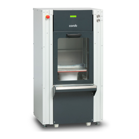
The gyroscopic mixer COROB™ CLEVERmix 700 with automatic clamping system allows mixing of non-explosive paints contained into
metal or plastic containers.
It is suitable to handle cans of dierent size and shape. With specially proled clamping plates available for installation upon request,
the machine can also handle square cans. The machine is also capable to mix more than one can simultaneously.
The bottom pull-out plate makes it easy and fast to load and unload cans.
The mixing cycle always ends with the can in vertical position and the clamping plates fully open.
The machine is equipped with a sliding door.
2.2 Standard control panel conguration
The machine features a membrane keyboard that allows to carry out a fully automatic mixing cycle ( key) or choose among pre-
set mixing cycles).
The adjusting keys and allow to manually vary the pre-set mixing time.
Display
The display shows the name of the mixing program selected, as well as the messages concerning the actions undertaken by the
machine during the automatic mixing cycle. The display lights up at machine start-up.

16 - INFORMATION AND TECHNICAL FEATURES
COROB™ CLEVERmix 700
AUTO key ( automatic program)
Key that allows you to select a fully automatic cycle. The mixing parameters are calculated based on can height.
Key to start / stop the cycle
This key allows to start the mixing cycle of a can. If pressed during machine operation, the cycle stops.
Key to select pre-set programs
Keys that allows you to select pre-set automatic mixing programs. They can be customized with text or a graphical representation of
the customer’s products.
Adjusting keys
Keys that allow you to modify the mixing time.
For more information on control panel functions and conguration, refer to chapter 5.
2.3 Performance and features
Mixing speed Automatic (based on can size) or pre-set (customized cycles)
Mixing time can be customized, manual set from 30 seconds to 20 minutes (up to 40 minutes
with tech conguration)
Clamping Automatic (based on can size) or pre-set (customized cycles)
Working cycle intermittent: periodic duty cycle max. 70%)
Direction of rotation of the mixing mechanics bi-directional
Type of can round - square - oval
Maximum can weight 35 kg / 77 lb
Minimum can height 100 mm
Maximum can height 400 mm (lower if can centering holder is present on bottom plate)
Maximum can diameter 390 mm
2.4 Technical data
Power supply Single-phase 200 - 240 V~ ± 10%
Single-phase 100 - 110 - 127 V~ ± 10% optional with autotransformer
Frequency 50/60 Hz
Fuses F 10 A
Max power absorbed 1050 W
Mixing motor power 0.75 HP (0.55 kW)
Noise level (*) Level of equivalent acoustic pressure:
< 70 dB (A)
Environment working conditions Temperature: between 10°C (50°F) and 40°C (104°F)
Relative humidity: between 5% and 85%, without condensation
(*) Value measured in laboratory and documented by the corresponding test report available at the manufacturer’s. Operating conditions: machine normal
working cycle, under simulated load conditions.

INFORMATION AND TECHNICAL FEATURES - 17
COROB™ CLEVERmix 700
2.5 Dimensions and weight
+
188 kg
-
415 lb
163 kg
-
360 lb
1058 mm - 41,7”
782 mm - 30,8”
1112 mm - 43,8”
805 mm - 31,7”
Adjusting height of the antivibration feet from 0” to 0.79” (0 to 25 mm).

BLANK PAGE
COROB™ CLEVERmix 700

INSTALLATION
3

BLANK PAGE
COROB™ CLEVERmix 700
Other manuals for CLEVERmix 700
1
Table of contents
Other corob Laboratory Equipment manuals
Popular Laboratory Equipment manuals by other brands

ANTAIRA
ANTAIRA INJ-C200G-bt-T Hardware manual

THORLABS
THORLABS PDX1 user guide

Thermo Scientific
Thermo Scientific Haematocrit-Rotor 7500 3473 Instructions for use

N-BIOTEK
N-BIOTEK NB-201M Operation manual

ScienTECH
ScienTECH 720 Installation, Operation and Care Manual

Bayer HealthCare
Bayer HealthCare Advia 70 Operator's guide

Velp Scientifica
Velp Scientifica F201A0500 instruction manual

BIO RAD
BIO RAD NGC quick guide

Du Pont
Du Pont SORVALL RC-5 Service manual

Thermo Scientific
Thermo Scientific Jewett Installation and operation manual

Pace
Pace TF 1500 Operation and maintenance manual

Terumo BCT
Terumo BCT Spectra Optia ESSENTIALS GUIDE