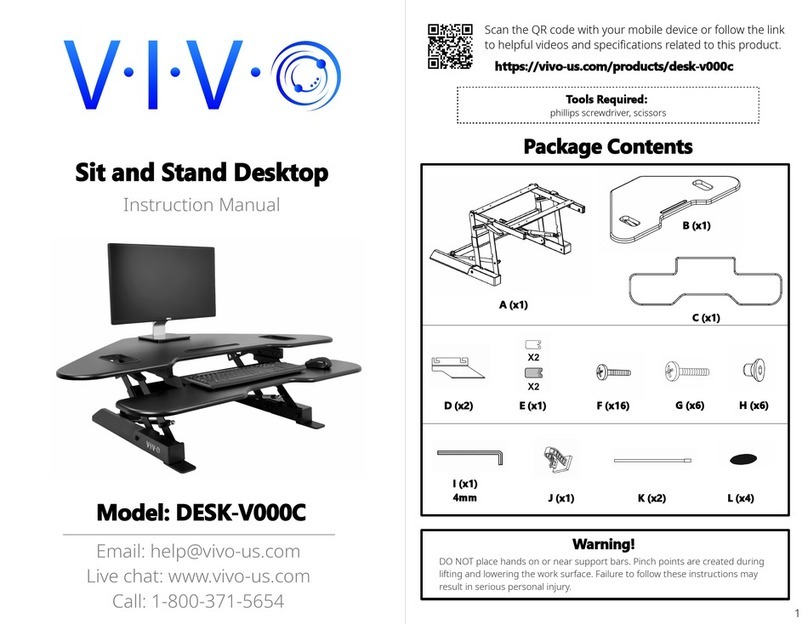
coronaDesking GO2 WorkCenter User manual

GO2Corner WorkCenter
Assembly Manual

2
eisys/healthcare, inc. corner 10.2010
1. COMPONENTS
Box (A) Frame and optional accessories
Box (B) Table top, Support Structure, Cable Outlets (3)
Unpack and layout all components from box (A). All the fasteners are in
individual bags taped to the relative component.
Frame 1 & 2
(4) short feet, (2) long feet
Options:
Monitor rail
(3) monitor rail posts
Cable Tray with or without MBMOU and power strip
Accessory Boxes
Position the two frames next to
each other. The control panel cable
always exits the cross rail at the
back of the frame.
The short feet always attach at
the back of the frame. The long
feet always attach at front of
frame. The center leg always has
2 short feet.
Raise legs to the highest posi-
tion. Remove frame covers from
both cross rails.
2. FRAME LAYOUT
•
•
•
•
•
•
•
•
•
•

3
eisys/healthcare, inc. corner 10.2010
3. ATTACHING THE TWO FRAMES
Remove the 6 T25 screws that secure the top of the frame cover
Remove the four screws and nuts indicated from Frame 2.
•
Remove the threaded pin as indicated from Frame 2.
•
Make sure all three (3) legs are at the exact same height before connecting the
drive shafts together.
•Now connect the two drive shafts.

4
eisys/healthcare, inc. corner 10.2010
3. ATTACHING THE TWO FRAMES
Tighten the four screws and nuts to both frames.
•
Line up the hole in the drive shaft on frame 1 with the hole in the drive shaft of frame 2.
(do this by manually raising and lowering the leg on frame 1; it will move freely because
it is not attached to the motor)
Insert threaded pin and tighten.
•
•
Now raise all three (3) legs to the highest position.
•

5
eisys/healthcare, inc. corner 10.2010
4. INSERTING GAS CYLINDERS
Remove top plates on all three legs and insert cylinders (align the bottom of the
cylinder by hand-screwing it into the bottom plate until you cannot turn it anymore)
•
•
•
1. Remove 8mm hex nuts (2) 2. Remove T25 screws (4) 3. Insert cylinder
Re-attach top leg plates (The two hex nuts should only be snug. Securely tighten the
4 screws)
1. Replace screws 2. Hex nuts should only be snug
Re-attach cable duct covers and 6 securing screws.

6
eisys/healthcare, inc. corner 10.2010
5. ATTACHING TABLE TOP
•Line up the top to the legs and fasten to all three legs.
Now you can attach the controls and the desk will be ready for up and down use.
•
**NOTE: DO NOT LOWER LEGS BEFORE TOP IS ATTACHED.
OR APPLY APPROXIMATELY 70LBS OF PRESSURE TO EACH LEG
WHILE LOWERING.

1
Heavy Duty
Height Adjustable Arm
with 3rd Post
Installation Instructions

2
Heavy Duty Height Adjustable Arm with 3rd Support Post(28-EI-RSRC)
Notice: Due to the weight of Diagnostic Monitors, specic heavy
duty tilter/vesa plate, arm and mounting cup must be used for
this equipment. In addition, a specially designed support post
(that correctly accommodates mounting of the heavy duty cup/arm
assembly) is also required and must be in place directly beneath
the monitor/arm assembly. The instructions below present the
specic parts and steps required to mount a larger scale Diagnostic
Monitor including instructions for converting an existing support
post (part# 28-EI-3-RSRC) that might be used as part of the
installation.
Note: It is critical and a requirement that any diagnostic monitor in
excess of 35 pounds be mounted per these instructions.

3
28-EI-3-RSRC (either previously purchased
or included with this order)
1. Parts List
Height Adjustable Arm with Tilter
Height Adjustable Arm Mounting Cup
Heavy duty top portion of the rail clamp
(2) of the M5-0.8X50 DIN 12.9 hardened steel bolts
for attaching clamp to the rail
(1) #8 metric 1.25x30mm hardened steel
countersunk head screw w/12.9 rating

4
2. ASSEMBLY
If you currently have a 28-EI-3-RSRC, remove the two silver screws and top portion
of the normal rail clamp. This top portion of the clamp should have two screw holes
that ARE NOT recessed and NO center threaded hole. Set aside this top piece and
the two silver screws
1.
Replace the top portion of the clamp with the HD portion using the (2) #4 metric Allen
head M5-0.8X50 DIN 12.9 hardened steel bolts in the recessed holes on top of the
new HD clamp.
2.
Using (1) #8 metric 1.25x30mm hardened steel countersunk head screw, attach the cup portion of
the Height Adjustable Arm with a 3/8” Allen wrench to the top clamp. Be sure to position the
cup recess over the small steel nipple. Tighten securely to a snug t.
Caution: Do not over tighten
3.

5
2. ASSEMBLY (cont.)
Insert the bottom portion of the Height Adjustable Arm into the cup.
4.
Attach the provided 100 X 200 vesa plate to the back of the monitor. Use the factory
screws when possible. Note: some monitor models may require the back housing to be
removed to accommodate the vesa plate (particularly the Barco 6MP Niofusion)
5.
The tilter portion of the arm will t into the top hole of the Height Adjustable Arm. To
adjust the tilter use the supplied Allen wrench to tighten or loosen the tilter mechanism
for the desired tilt angle of the monitor.
6.

2. ASSEMBLY (cont.)
To calibrate the arm’s tension so the monitor will stay in place once positioned, extend
the monitor arm fully and position both joints parallel to the desk top. Use the supplied
Allen wrench and insert where indicated (with the red arrow). Turn the Allen wrench
clockwise to loosen the tension and counterclockwise to tighten the tension. The arm
is calibrated when the monitor stays at the level that the user positions it and does not
‘drift’ when released.
7.


205.941.1942
Birmingham, AL
forward thinking solutions
info@coronagroupinc.com
coronagroupinc.com
coronagroupinc
c
For additional technical information and help,
contact the following:
Installations
Greg Hutchens
(c) 205.902.6161
(e) greg.hutchens@coronagroupinc.com
Customer Service
Shawn Dyck
(p) 205.329.7070
(e) shawn.dyck@coronagroupinc.com
Customer Service
Alicia Burrow
(p) 205.329.7057
(e) alicia.burrow@coronagroupinc.com
Other manuals for GO2 WorkCenter
1
Table of contents
Popular Office Equipment manuals by other brands

VISIONARY DESIGNS
VISIONARY DESIGNS RE-710 Setup instructions

Neopost
Neopost IM 30 Operator's manual

OCEE DESIGN
OCEE DESIGN Den Seat SASS-0079 A Assembly instructions

Ergotron
Ergotron Anthro-DNA Steve's Station Essential Assembly instructions

NComputing
NComputing L110 Series user guide

Reiner
Reiner C operating instructions