Corsair RGB ELITE H60x User manual

ENGLISH
TABLE OF CONTENTS
Note: Most newer PC cases include a CPU cut-out to allow access to the bottom of the motherboard.
If your case does not include a cut-out, you will need to remove your motherboard from the case prior
to installation. ELITE Series coolers come with the Intel mounting bracket pre-installed on the pump for
quick installation.
INTEL (All Sockets)
AMD AM5/AM4
FINISHING UP YOUR INSTALLATION
FAQ

ENGLISH
ENGLISH INTEL
ENGLISH
ENGLISH INTEL
V5+
D
DNG
2
3
1
B C
A
DE F
G
H
I
LK
J
N
M
x4 INTEL 1200/1156/1155/1151/1150
STANDOFFS
x4 INTEL 2066/2011-3/2011 STANDOFFS x4 INTEL 1700 STANDOFFS
x1 INTEL BACKPLATE
(1200/115X/1700 ONLY )
x1 INTEL MOUNTING BRACKET
(PRE-INSTALLED)
x4 THUMB NUTS
x4 AMD AM5/AM4 STANDOFFS x1 AMD AM5/AM4 MOUNTING BRACKET
ARGB CABLE
Y-SPLITTER x4 LONG FAN SCREWS (H60x)
x8 LONG FAN SCREWS (H100x)
x4 RADIATOR SCREWS (H60x)
x8 RADIATOR SCREWS (H100x)
x8 WASHERS (H60x/H100x) x1 SP120 RGB ELITE (H60x)
x2 SP120 RGB ELITE (H100x)
INCLUDED HARDWARE
Highlighted parts for Intel installation only

ENGLISH
ENGLISH
D
CLGA 1700
BLGA 2011/
2011-3/2066
ALGA 1200/1150/
1151/1155/1156
> Attach the provided Intel standoff for
your socket.
> Use (A) for LGA 1200/115X, (B) for
LGA 2011/2011-3/2066 or (C) for
LG A 170 0.
> Tighten all four standoffs until firmly
secured.
Adjust backplate for your required socket.
NOTE: Intel LGA 2066/2011-3/2011
do not require backplate installation.
Proceed to step 2.
2. INSTALLING THE INTEL STANDOFF SCREWS
1. INSTALLING THE INTEL BACKPLATE

ENGLISH
ENGLISH
Please continue to Page 7 to continue your installation.
K
N
M
L
F
Attach the radiator and the fans as shown.
For the best cooling performance, we
recommend mounting the fans as an
air-intake to your PC case.
> Align the bracket and pump over the
standoff screws as shown.
> Attach the thumb nuts (F) to the standoff
screws as shown.
> Tighten the thumb nuts until all four corners
are firmly secured.
4. INSTALLING THE PUMP UNIT
3. INSTALL THE FANS AND RADIATOR

ENGLISH
ENGLISH AMD AM5/AM4
V5+
D
DNG
2
3
1
B
C
A
D
E
F
G H I
LK
J
N
M
INCLUDED HARDWARE
Highlighted parts for AMD AM5/AM4 installation only
x4 INTEL 1200/1156/1155/1151/1150
STANDOFFS
x4 INTEL 2066/2011-3/2011 STANDOFFS x4 INTEL 1700 STANDOFFS
x1 INTEL BACKPLATE
(1200/115X/1700 ONLY )
x1 INTEL MOUNTING BRACKET
(PRE-INSTALLED)
x4 THUMB NUTS
x4 AMD AM5/AM4 STANDOFFS x1 AMD AM5/AM4 MOUNTING BRACKET
ARGB CABLE
Y-SPLITTER x4 LONG FAN SCREWS (H60x)
x8 LONG FAN SCREWS (H100x)
x4 RADIATOR SCREWS (H60x)
x8 RADIATOR SCREWS (H100x)
x8 WASHERS (H60x/H100x) x1 SP120 RGB ELITE (H60x)
x2 SP120 RGB ELITE (H100x)

ENGLISH
ENGLISH
E H
Figure 1 Figure 2
K
N
M
L
> Remove the integrated Intel mounting
bracket (Figure 1).
> Install the AMD AM5/AM4 bracket by
pushing both sides into the slot on the
pump until secure (Figure 2).
Note: It is important that the AMD AM5/AM4
retention bracket be evenly secured on
all sides before installation.
Attach the radiator and the fans as shown.
For the best cooling performance, we
recommend mounting the fans as an
air-intake to your PC case.
2. INSTALL THE FANS AND RADIATOR
Remove the existing AMD AM5/AM4
mounting brackets shown.
3. PREPARE THE MOTHERBOARD FOR INSTALLATION
1. INSTALLING THE AMD AM5/AM4 MOUNTING BRACKET

ENGLISH
ENGLISH
G
F
Please continue to Page 7 to continue your installation.
Align the bracket with the AMD AM5/AM4
standoffs as shown. Tighten the thumb
nuts (F) until secure.
> Attach the provided AMD AM5/AM4
standoffs to the CPU socket.
> Tighten all four screws until firmly secure.
5. INSTALLING THE PUMP UNIT
4. INSTALLING THE AMD AM5/AM4 STANDOFF SCREWS

ENGLISH
ENGLISH
Figure 1 Figure 2
3-PIN
V5+
D
DNG
2
3
1
> Connect pump tach cable to the CPU_FAN header on your motherboard (Figure 1).
> Connect each fan to the Y-splitter cable (J) then plug the Y-splitter cable into a 4-pin header on your
motherboard. (Figure 2)
> Connect the pump and fans into the ARGB cable (I). For best lighting playback, connect the pump into
connector #1 and the fan(s) on connector #2 and #3. Plug the ARGB cable into the ARGB header on a
compatible motherboard.
CONNECT PUMP AND FANS TO MOTHERBOARD
CONNECT PUMP AND FANS TO ARGB
Note: The pump and fan LEDs get power from the motherboard or control device. If they are not
connected, they will not illuminate.
654 3 2 1
FANS
RGB
TEMP 2
TEMP 1
ID
654321
RGB HUB
B
A
> Alternatively, for the full iCUE experience, connect the 4-pin fan and 4-pin RGB headers into the “Fans” (A)
and “RGB HUB” (B) headers on an iCUE COMMANDER CORE XT (sold separately).

ENGLISH
ENGLISH
FAQ
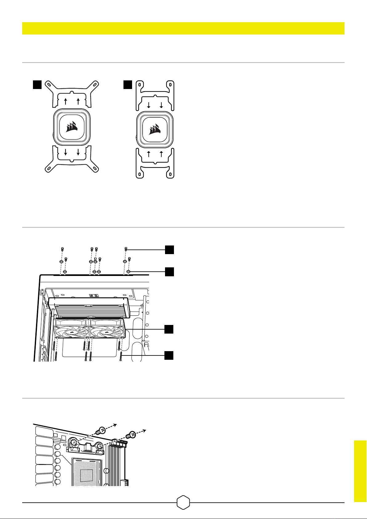
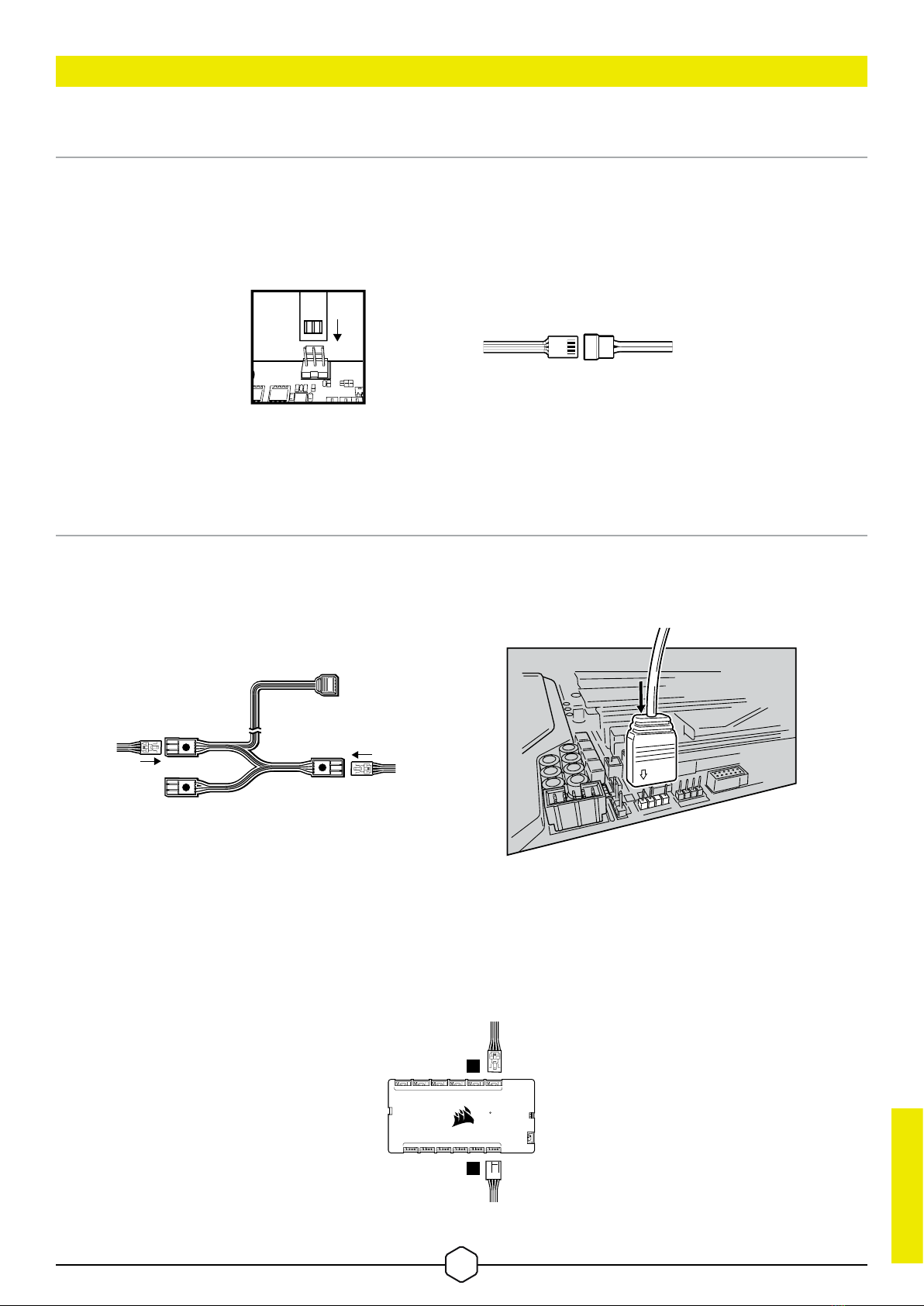
1. How do I know the direction of the airflow of the fan?
An arrow located on the side of the fan indicates the direction of airflow.
2. Can I reuse the pre-applied thermal paste on the cooler for re-installation?
Re-installation of the cooler will require you to clean off the pre-applied thermal paste and apply
an aftermarket paste.
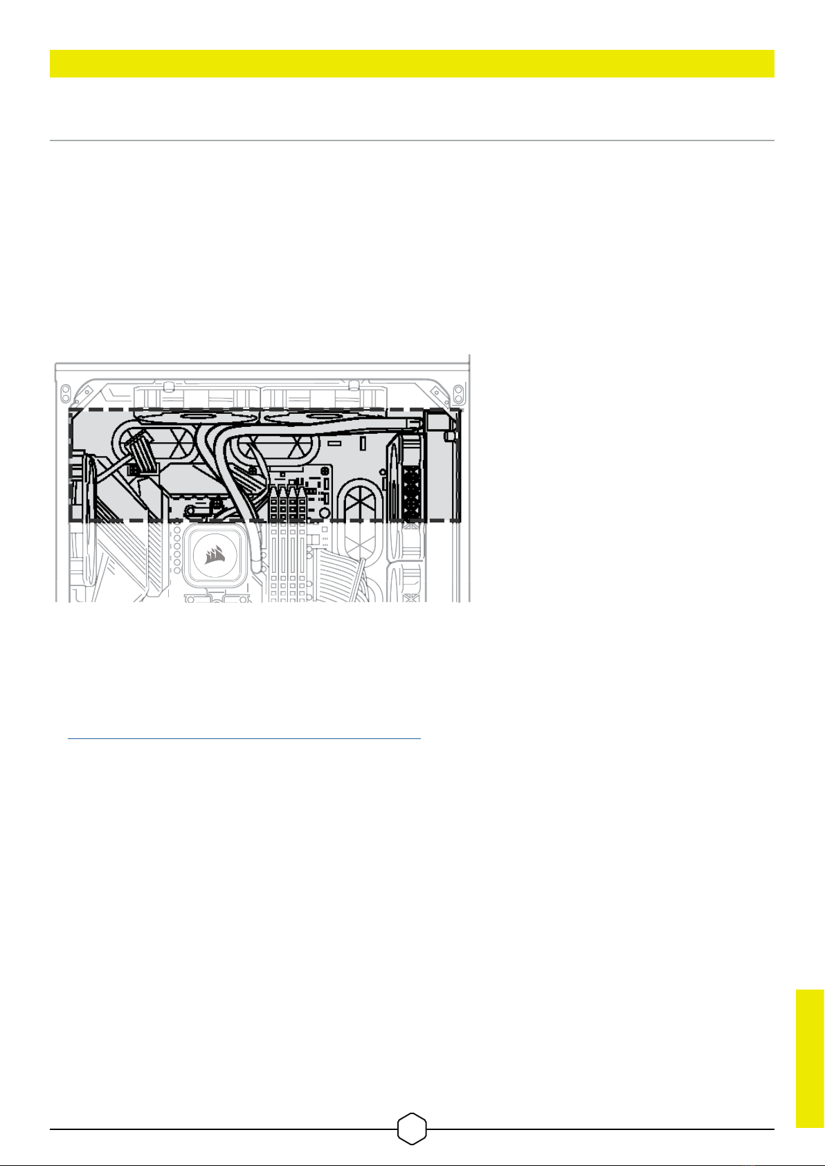
3. What orientation should I install my radiator?
The best way to install a radiator is with the tubes on the bottom of the case, though you can install it
with the tubes in any position, including an inverted radiator, as long as the highest point in the radiator
is visibly higher than the CPU pump.
4. My cooler and fans are blinking red or not functioning. What do I do?
Please double check all connections between the cooler and fans. Ensure that the cooler is updated
to the most recent firmware via iCUE. If this does not resolve your problems, please open a support
ticket at support.corsair.com or contact our customer support team for further troubleshooting and
assistance.
https://help.corsair.com/hc/en-us/requests/new
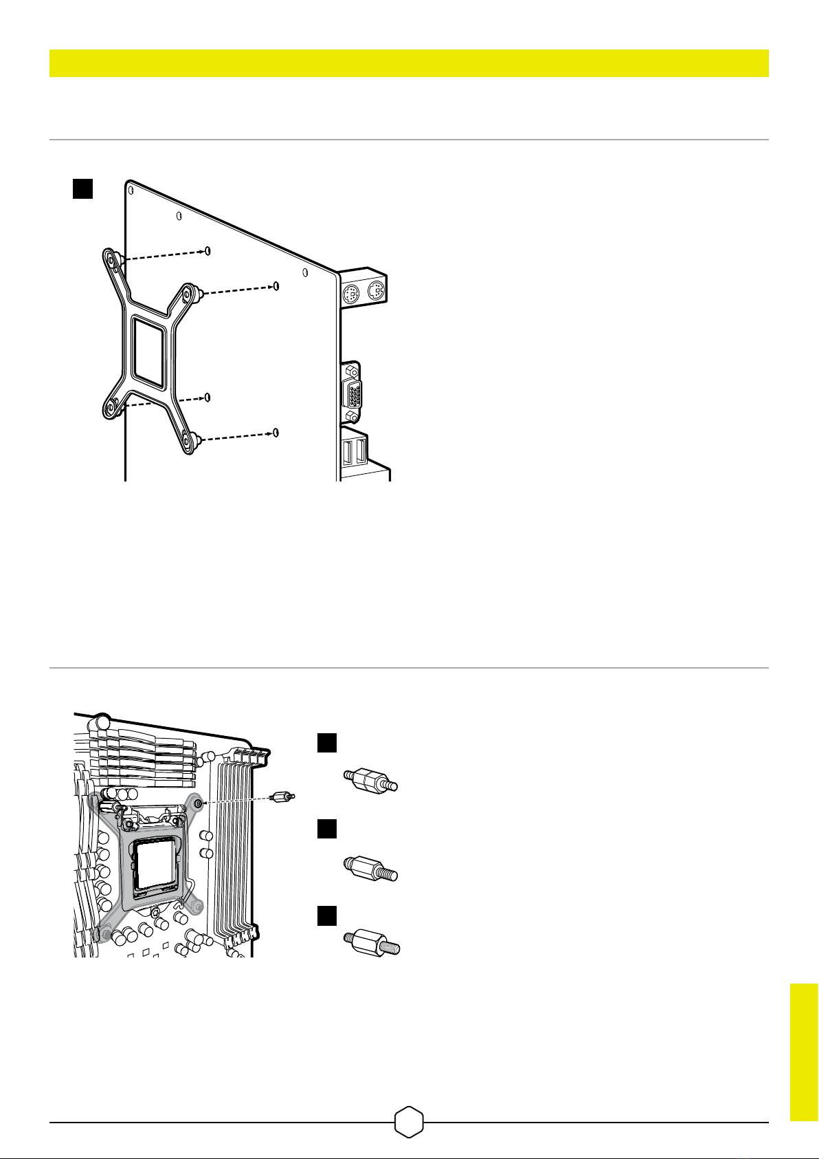
5. What should I do if my cooler backplate feels loose after installation?
It is common for your cooler backplate to feel loose after you install it into your motherboard for the
first time. Once you have seated and tightened down the cooler pump, it will pull the backplate to the
motherboard and apply pressure on the socket via the cooler.
IMPORTANT: Do NOT, under any circumstances, add additional washers and spacers to your
backplate to decrease play in the backplate. Doing so will increase the mounting pressure to the
retention kit and potentially damage your retention kit, motherboard, or socket.

5
•
A
R
E
A
P
P
L
I
C
A
B
L
E
•
L
O
C
A
L
C
O
U
N
T
R
Y
R
E
G
U
L
A
T
I
O
N
S
© 2023 CORSAIR MEMORY, Inc. All rights reserved. CORSAIR and the sails logo are
registered trademarks of CORSAIR in the United States and/or other countries. All other
trademarks are the property of their respective owners. Product may vary slightly from
those pictured.
49-002680 AA
Warranty: corsair.com/support/warranty
Phone: (888) 222-4346
Web: corsair.com Support: support.corsair.com
Blog: corsair.com/blog
Forum: forum.corsair.com
YouTube: youtube.com/corsairhowto
This manual suits for next models
1
Table of contents
Other Corsair Accessories manuals