Cosmo CPB User manual
Hocheffizienz-Brauchwasserpumpe
High Efficiency HWR Pump
Vysoce účinné čerpadlo na užitkovou vodu
CPB, CPBA
de Einbau- und Betriebsanleitung
en Installation and operating instructions
cz Návod k instalaci a obsluze
GUTESKLI M A
BESSER LEBEN

2
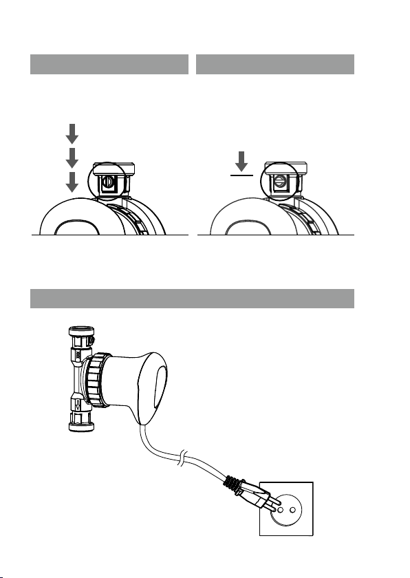
Fig. 1 Fig. 2
Fig. 3 Fig. 4
1 1
3
5
24
3
Fig. 5 Fig. 6
Fig. 7

4
EG-KONFORMITÄT
Dieses Produkt entspricht den geltenden europäischen Richtlinien sowie
den ergänzenden nationalen Anforderungen und Normen. Die Konformität
wurde nachgewiesen. Die EG-Konformitätserklärung des Produktes kann
unter www.cosmo-info.de abgerufen oder direkt bei der COSMO GmbH
angefordert werden.
CE CONFORMITY
This product meets the applicable European directives and the
complementary national requirements and standards. Conformity has
been proven. The declaration of conformity can be retrieved under
www.cosmo-info.de or directly from COSMO GmbH.
PROHLÁŠENÍ ES
Tento výrobek vyhovuje platným evropským směrnicím a doplňkovým vni-
trostátním požadavkům a normám. Shoda byla prokázána. ES prohlášení
o shodě výrobku je k dispozici na adrese www.cosmo-info.de, nebo si je
lze vyžádat přímo u rmy COSMO GmbH.

5
DE Deutsch Seite 6
EN English Page 12
CZ Česky Strana 18

Deutsch
6
1 Sicherheit
• Vor Arbeiten an der Pumpe Betriebsanleitung vollständig
durchlesen.
• Diese Anleitung ist Teil der Pumpe, gültig für die genannten
Baureihen, und beschreibt den sicheren und sachgemäßen
Einsatz in allen Betriebsphasen.
• Installation der Pumpe nur durch einen qualizierten
Fachinstallateur durchführen lassen.
• Der Elektroanschluss darf nur durch eine Elektrofachkraft
vorgenommen werden.
• Vor allen Montage- und Wartungsarbeiten Pumpe span-
nungsfrei schalten und gegen Wiedereinschalten sichern.
• Nach der Installation die Anleitung an den Eigentümer
weitergeben. Betriebsanleitung vollständig und lesbar
halten und jederzeit zugänglich aufbewahren.
• Die Pumpe nur in technisch einwandfreiem Zustand sowie
bestimmungsgemäß, sicherheits- und gefahrenbewusst
unter Beachtung dieser Anleitung betreiben.
• Diese Umwälzpumpe ist nur für Trinkwasser geeignet.
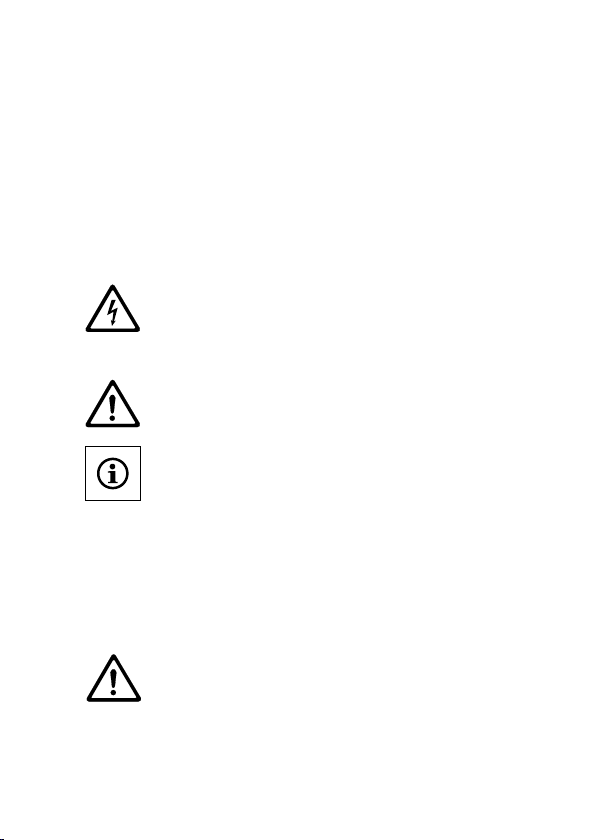
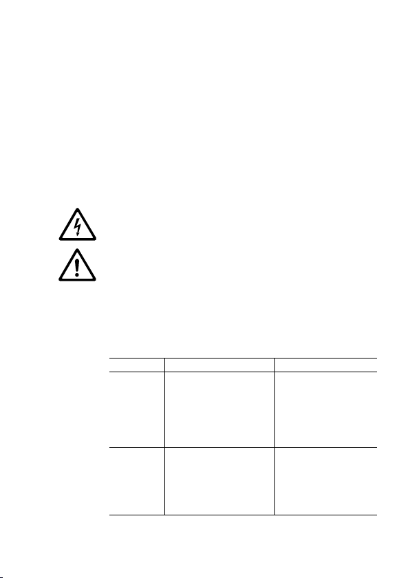
2 Warnhinweise
GEFAHR! Unmittelbar drohende Gefahr. Tod, schwere
Körperverletzung möglich.
WARNUNG! Mögliche drohende Gefahr. Tod, schwere
Körperverletzung möglich.
VORSICHT! Mögliche gefährliche Situation. Leichte
Körperverletzung, Sachschaden möglich.
INFO! Information, Handlungshinweis.

Deutsch
7
3 Technische Daten
3.1 Typenschlüssel
COSMO Baureihe
(Hochefzienz-Brauchwasserpumpe mit EC-Kugelmotor)
CPB Typenbezeichnung
(A = mit Absperrarmaturen)
3.2 Daten
Max. Förderhöhe 1,1 mWS
Max. Fördermenge 650 l/h
Elektr. Anschluss 1~115-230V / 50-60Hz
Leistungsaufnahme 7 Watt
Schutzart IP 42
Druckfestigkeit 10 bar (1000 kPa)
Temperaturfestigkeit 95°C
Medientemperatur bis 75°C
Umgebungstemperatur bis 40°C
zulässige Wasserhärte unbegrenzt
Trockenlaufschutz ja
4 Anschlüsse, Einbaumaße
• COSMO CPB (Fig. 1)
Schraubanschluss: 15 (Rp 1/2")
Einbaulänge: 85 mm
• COSMO CPBA (Fig. 2)
Schraubanschluss: 15 (Rp 1/2") und Absperrarmaturen (1")
Einbaulänge: 139 mm
Deutsch
8
5 Lieferumfang
• Pumpe
• Wärmedämmschale
• Rückschlagventil und Absperrventil
(Typ COSMO CPBA)
• Dichtringe (Typ COSMO CPBA)
• 1,5 m-Anschlusskabel mit Eurostecker
• Einbau- und Betriebsanleitung
6 Installation
GEFAHR! Tod durch Stromschlag!
Vor Beginn der Arbeiten Spannungsfreiheit sicherstellen.
1. Für den Einbau einen witterungsgeschützten, frost- und
staubfreien und gut belüfteten Raum vorsehen.
2. Gut zugänglichen Einbauort auswählen.
VORSICHT! Schmutz kann die Pumpe funktionsunfähig
machen. Rohrsystem vor Einbau durchspülen.
INFO! Die Pumpe nur komplett einbauen bzw. austauschen
(Motor und Pumpengehäuse ). Die Montage des Motors auf ein
Fremdpumpengehäuse ist nicht möglich.
INFO! Beim Pumpentyp COSMO CPBA sind Absperrventil
und Rückschlagventil im Lieferumfang enthalten und mit
einem Anzugsdrehmoment von 15 Nm dichtend zu montieren
(Fig. 2).
Beim Pumpentyp COSMO CPB müssen Absperrventil und
Rückschlagventil (Öffnungsdruck max. 0,16 kPa) zusätzlich
montiert werden.
VORSICHT! Ein zu hohes Anzugsmoment beim Verschrauben
zerstört die Ventilverschraubungen und die O-Ringe. Beim
Einbau die Ventile mit einem Maulschlüssel gegen Verdrehen
sichern!
3. Motor mit dem Pumpengehäuse verschrauben

Deutsch
9
VORSICHT! Die Gehäusedichtung ist auf dem Pumpenmotor
vormontiert und durch eine Banderole gesichert. Vor Montage
des Motors Banderole abziehen.
4. Einbauort so vorbereiten, dass die Pumpe frei von
mechanischen Spannungen montiert werden kann.
5. Zulässige Einbaulage wählen (Fig. 4).
6. Pumpe so in die Rohrleitung einbauen, dass die Pfeile auf
dem Pumpengehäuse in Fließrichtung zeigen (Fig.3).
7. Pumpenkopf so drehen, dass das Kabel nach unten zeigt.
Hierzu ggf.
8. Überwurfmutter
wieder lösen, Pumpenkopf bei Bedarf
ganz abschrauben.
INFO! Die Pumpe verfügt über einen Trockenlaufschutz. Eine
Funktionsprüfung des Rotors außerhalb des Mediums führt zu
einem wiederholten Anhalten und Wiederanlaufen des Rotors.
Erst bei Betrieb im luftfreien Medium läuft der Rotor ohne
Unterbrechung.
VORSICHT! Sachschaden durch Wasseraustritt!
Im Auslieferzustand ist das Absperrventil geöffnet (Fig. 5).
Vor dem Lösen der Überwurfmutter Absperrventil schließen.
Hierzu mit einem Schraubendreher den Schlitz quer zur Fließ-
richtung stellen (Fig. 6).
VORSICHT! Lagerschaden durch Trockenlauf!
Leitungssystem gründlich mit Wasser durchspülen und
entlüften.
VORSICHT! Gehäusedichtung nicht beschädigen. Beschädigte
Dichtung austauschen.
VORSICHT! Bei Montage der Pumpengehäusedichtung diese
nicht ins Pumpengehäuse, sondern auf den Pumpenmotor legen.
9. Pumpenkopf wieder montieren, Überwurfmutter mit
ca. 20 Nm Anzugsmoment wieder anziehen.
10. Wärmedämmschale auf das Pumpengehäuse setzen.
11. Wasserzufuhr/Absperrhähne langsam öffnen.
Deutsch
10
7 Elektrischer Anschluss
1. EuroStecker in Steckdose einstecken.
2. Ggf. Stromzufuhr herstellen. Die Pumpe beginnt sofort zu
laufen.
8 Entlüften
1. Luftfreie Zirkulation sicherstellen.
2. Bis Pumpe rauschfrei läuft, zur Unterstützung der
Entlüftung Pumpe mehrmals ein- und ausschalten und
Warmwasserzapfstelle mehrmals öffnen.
9 Wartung
GEFAHR! Tod durch Stromschlag
Vor Beginn der Arbeiten Spannungsfreiheit sicherstellen.
WARNUNG! Verbrühungsgefahr!
Vor Wartungsarbeiten die Pumpe abkühlen lassen.
Pumpeninnenraum und Rotor können mit handelsüblichen
Kalklösemitteln gereinigt werden. Hierzu kann der Rotor bei
Bedarf entnommen werden. Vor Ausbau des Pumpenkopfes
(siehe Schritte 8. und 9. im Kapitel 6.) Absperrventile schließen.
10 Störungen und Abhilfemaßnahmen
Störung Ursache Abhilfe
Pumpe läuft
nicht.
Stromzufuhr ist unterbro-
chen.
Pumpe/Motor defekt
(Elektrik/Elektronik).
Rotor blockiert durch
Ablagerungen.
Rotor blockiert, da Rotorla-
ger defekt/ verschlissen.
fKorrekte Stromzufuhr
wiederherstellen.
fPumpe tauschen.
fWasserberührte Teile
reinigen.
fRotor oder Pumpe
tauschen.
Pumpe
macht
Geräusche.
Luft im Pumpenge häuse/
Trockenlauf.
Rotorlager defekt.
Rückschlagventileinsatz
ist locker.
fZirkulationsleitung
entlüften.
fRotor tauschen. Bei
beschädigtem Lagerstift
Pumpe tauschen.
fRückschlagventil
tauschen.
Lässt sich die Störung nicht beheben, Fachhandwerker
kontaktieren.

11
English
12
1 Safety
• Read the operating instructions before working on the pump.
• These instructions are part of the product, are valid for all
series named and describe how to use the product safely
and correctly during all operating phases.
• Installation of the pump may only be performed by qualied
personnel.
• Have all electrical work carried out by qualied electricians
only.
• Before carrying out any installation or maintenance work,
disconnect pump from power supply and ensure it cannot
be reconnected unintentionally.
• Once installation work is complete, pass the instructions on
to the end user. Keep the operating instructions complete,
in a legible condition and permanently accessible.
• Only operate the pump if it is in perfect technical condition;
only use it as intended, staying aware of safety and risks,
and adhering to the instructions in this manual.
• This circulator is suitable for drinking water only.
2 Safety information
DANGER! Immediate acute risk. Fatal or serious injury may
occur.
WARNING! Potential acute risk. Fatal or serious injury may
occur.
CAUTION! Potential hazardous situation. Light injury, damage
to device may occur.
NOTE! Information, instruction.

English
13
3 Technical Data
3.1 Type key
COSMO Series
(High Efciency HWR pump with spherical motor
with ECM technology)
CPB Type designation
(A = with check valves)
3.2 Data
Max. delivery head 1.1 m
Max. delivery rate 650 l/h
Voltage 1~115-230V / 50-60Hz
Power consumption 7 Watt
Protection class IP 42
Compression strength 10 bar (1000 kPa)
Temperature resistance 95°C
Max. uid temperature 75°C
Max. ambient temperature 40°C
Permitted water hardness no limitation
Dry run protection yes
4 Connections, installation dimensions
• COSMO CPB (Fig. 1)
Screwed connection: 15 (Rp 1/2")
Centre distance: 85 mm
• COSMO CPBA (Fig. 2)
Screwed connection: 15 (Rp 1/2") and check valves (1")
Centre distance: 139 mm

English
14
5 Scope of delivery
• Pump
• Insulation shell
• Non-return valve and stop valve
(Type COSMO CPBA)
• Sealing rings (Type COSMO CPBA)
• 1.5 m- cable with Euro plug
• Installation- and operating instructions
6 Installation
DANGER! Electrocution!
Before starting work, disconnect pump from power supply.
1. Provide a weatherproof, frost-free, dust-free and well-
ventilated room for the installation.
2. Choose an installation site that is easily accessible.
CAUTION! Dirt can cause the pump to fail. Flush pipework
before installation.
INFO! Use the pump motor with the included pump housing
only. The pump motor does not t to other pump housings in
the market.
NOTE! As to the COSMO CPBA version, stop valve and
non-return valve are within the delivery scope and have to be
mounted and sealed with a tightening torque of 15 Nm
(hand-tight, Fig. 2).
As to the COSMO CPB version, stop valve and non-return
valve (opening pressure max. 0.16 kPa) have to be installed in
addition.
CAUTION! Screwing with excessive tightening torque
destroys the valve screw connections and the O-rings. When
installing the valves, use a xed spanner to prevent twisting!
3. Mount the pump motor to the pump housing.
English
15
CAUTION! The sealing ring is preassembled to the pump
motor and xed by a sleeve. Prior to the pump motor assembly,
remove the sleeve from the motor.
4. Make sure, that the pump can be installed without being
exposed to mechanical stresses.
5. Choose the right installation position (Fig. 4).
6. Install the pump in the right direction (arrows on the pump
housing indicate the ow, Fig.3).
7. Turn the motor head so that the cable points downwards.
Where appropriate:
8. Release the union nut . Unscrew the motor head com-
pletely, if necessary.
INFO! The pump is equipped with dry run protection. A pump
run with the pump motor disassembled shows a repeated
start and stopping of the rotor. A continuous pump run is
possible within the vented recirculation system only.
CAUTION! Damage to device caused by water extrusion!
As to the COSMO CPBA version, the pump is delivered with
the stop valve open (Fig. 5). Before releasing the union nut,
close the stop valve by turning the slot with a screw driver in a
position across the direction of the ow (Fig. 6).
CAUTION! Damage to bearings caused by dry running!
Thoroughly ush pipework and bleed afterwards.
CAUTION! Do not damage the housing seal. Replace
damaged sealing ring.
CAUTION! When mounting the sealing ring, do not place it in
the pump housing but apply it onto the pump motor.
9. Remount the motor head and fasten union nut with
approx. 20Nm torque.
10. Fit the insulation shell .
11. Open water supply/stop valves slowly.

English
16
7 Electrical connection
1. Plug in the Euro-plug in socket.
2. Activate power supply, where necessary. The pump starts
immediately.
8 Venting
1. Ensure the return line to be air-free.
2. To achieve a noiseless pump run, switch the pump on and
off repeatedly and open a hot water tap several times.
9 Maintenance
DANGER! Electrocution!
Before starting work, disconnect pump from power supply.
WARNING! Danger of scalding!
Before starting work, allow the pump to cool down.
The interior of the pump as well as the rotor may be cleaned
with usual descaling agents. For this purpose the rotor may
be removed from the motor. Close the stop valves before
unscrewing the motor head (see steps 8. and 9. in chapter 6.).
10 Faults and corrective measures
Fault Causes Remedies
Pump not
running.
Power supply is inter-
rupted.
Pump/motor is defective
(electrical/electronics).
Rotor is blocked by
deposits.
Rotor is blocked due to
wear of the rotor bearing.
fEnsure correct power
supply.
fExchange pump.
fClean wetted parts.
fExchange rotor or
pump.
Pump is
making
noise.
Air in the pump housing/
pump is running dry.
Defective rotor bearing.
Insert of non-return valve
is loose.
fBleed the return line.
fExchange rotor. Ex-
change the pump, if the
bearing pin is damaged.
fExchange non-return
valve.
If you cannot remedy the fault, contact your local dealer.

17

18
Česky
1 Bezpečnost
● Před prací na čerpadle si důkladně pročtěte návod k obsluze.
● Tento návod je součástí čerpadla, platí pro uvedené konstruk-
ční řady a popisuje bezpečné a správné použití během všech
fází provozu.
● Instalaci čerpadla smí provádět pouze kvalikovaný odborný
technik.
●Elektrické připojení smí provádět pouze kvalikovaný elektrikář.
● Před veškerou montáží a údržbou odpojte čerpadlo od napáje-
ní a zajistěte proti opětovnému zapnutí.
● Po instalaci předejte návod majiteli. Návod k obsluze udržujte
kompletní a čitelný a uschovejte jej vždy na přístupném místě.
● Čerpadlo provozujte pouze v technicky bezvadném stavu,
v souladu s určením, bezpečně a s vědomím nebezpečí a
respektujte tento návod.
● Toto cirkulační čerpadlo je vhodné pouze na pitnou vodu.
2 Výstražnépokyny
NEBEZPEČÍ! Bezprostředně hrozící nebezpečí. Je možné usmr-
cení nebo vážné zranění.
VAROVÁNÍ! Možné hrozící nebezpečí. Je možné usmrcení nebo
vážné zranění.
POZOR! Potenciálně nebezpečná situace. Je možné lehké zraně-
ní nebo poškození majetku.
INFO! Informace a instrukce.

19
Česky
3 Technickéúdaje
3.1 Typovýkód
COSMO Konstrukční řada
(Vysoce účinné čerpadlo užitkové vody s kulovým
motorem ES)
CPB Typové označení
(A = s uzavíracími armaturami)
3.2 Údaje
Max. dopravní výška 1,1 mWS
Max. čerpané množství 650 l/h
Elektr. přívod 1~ 115–230 V / 50–60 Hz
Příkon 7 W
Krytí IP 42
Pevnost v tlaku 10 bar (1000 kPa)
Teplotní odolnost 95 °C
Teplota média až 75 °C
Okolní teplota až 40 °C
Dovolená tvrdost vody neomezená
Ochrana proti chodu nasucho ano
4 Přípojky,montážnírozměry
●COSMOCPB(Obr.1)
Šroubové připojení: 15 (Rp 1/2“)
Montážní délka: 85 mm
●COSMOCPBA(Obr.2)
Šroubové připojení: 15 (Rp 1/2“) a uzavírací armatury (1“)
Montážní délka: 139 mm
20
Česky
5 Rozsahdodávky
●Čerpadlo
● Tepelně izolační plášť
● Zpětný ventil a uzavírací ventil
(typ COSMO CPBA)
● Těsnicí kroužky (typ COSMO CPBA)
● Připojovací kabel 1,5 m se zástrčkou Euro
● Návod k instalaci a obsluze
6 Instalace
NEBEZPEČÍ!Smrtvdůsledkuúrazuelektrickýmproudem!
Před zahájením prací zajistěte odpojení od napájení.
1. Pro instalaci naplánujte dobře větranou místnost chráněnou
proti povětrnostním vlivům, mrazu a prachu.
2. Vyberte dobře přístupné místo instalace.
POZOR! V důsledku nečistot se může čerpadlo stát nefunkční.
Potrubní systém před instalací propláchněte.
INFO! Čerpadlo instalujte, resp. vyměňte jen jako celek (motor
a těleso čerpadla). Montáž motoru na cizí těleso čerpadla není
možná.
INFO! U čerpadla typu COSMO CPBA jsou uzavírací ventil a
zpětný ventil zahrnuty v rozsahu dodávky a je nutné je těsně
namontovat utahovacím momentem 15 Nm (Obr.2).
U čerpadla typu COSMO CPB musí být dodatečně namontován
uzavírací ventil a zpětný ventil (otevírací tlak max. 0,16 kPa).
POZOR! Nadměrným utahovacím momentem při sešroubování
se poškodí šroubení ventilu a O-kroužky. Při instalaci zajistěte
ventily otevřeným klíčem proti otáčení!
3. Motor sešroubujte s tělesem čerpadla
This manual suits for next models
1
Table of contents
Languages:
Other Cosmo Water Pump manuals


Popular Water Pump manuals by other brands

Agilent Technologies
Agilent Technologies InfinityLab LC Series user manual

Grundfos
Grundfos CM SP Service instructions

Emerson
Emerson Penberthy U Installation, operation and maintenance instructions

Powerex
Powerex LVP0157 manual

Flotec
Flotec FP4200 Series owner's manual

Dover
Dover PSG ALL-FLO A150 Installation, operation & maintenance manual


