INSTALLATION MANUAL SAFETY 5
Wash the cover with harsh chemicals or
cleaners.
Use an extension cord to connect the Covana
cover to its power source. The cord may not be
properly grounded and the connection is a shock
hazard. An extension cord may cause a voltage
drop, which would cause the motor to overheat.
CAUTION
Be sure to follow all instructions in this manual
and use only accessories and tools approved by
Covana.
Do not roll the Covana cover onto its side or slide
it on its side. This will damage the siding.
After removing a part, always place it in a safe
place on a clean and level surface to ensure
proper functionality.
All four jacks of the Covana cover must be
properly anchored to the foundation using the
anchoring holes located at the foot of each jack.
The optional non-permanent mounting plates
can be used when anchoring is not possible, but
under strict condition. See ‘’Non-permanent
mounting plates installation” section for details.
This product mainly contains steel, plastic,
copper (Cu) and die-cast aluminum (Al). The
gearbox contains oil and other materials. Please
recycle them properly.
Both the up and down limit switches are pre-
adjusted at the factory. The down-limit switch
should never be re-adjusted. The up-limit switch
should be re-adjusted only to reduce the
maximum height of the cover to avoid possible
contact with its surroundings. Please refer to the
Limit Switch Adjustment section in this manual
before making any adjustments. An improper
adjustment can result in damage to the drive
system and/or cover.
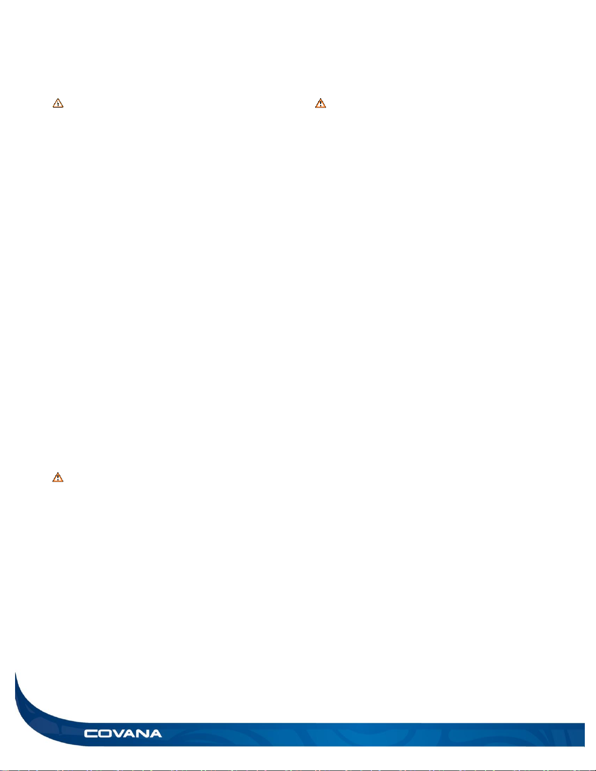
Avoiding the risk of electrocution
ELECTRICAL DANGER
Failure to comply with these instructions may
result in death by electrocution or serious injury.
Disconnect or turn off and secure all power
supplies before starting any intervention on the
Covana cover.
Always have a licensed electrical contractor
perform any electrical maintenance or repairs on
the Covana cover. The wiring must comply with
all applicable local electrical codes and
regulations.
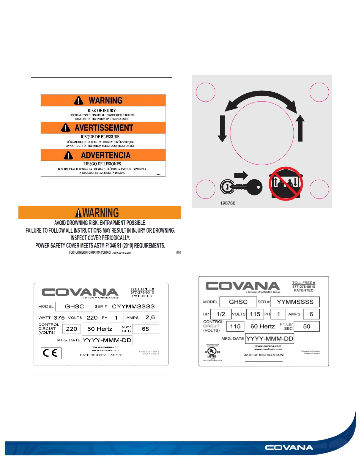
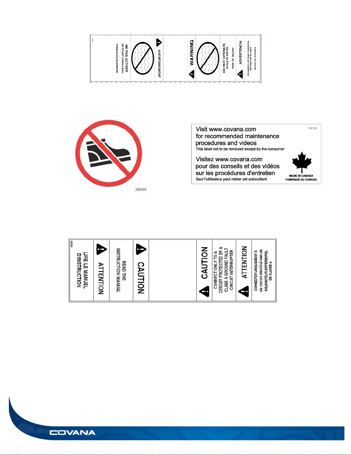
The Covana operator must be connected to a
circuit that is protected by a Class A dedicated
ground-fault circuit-interrupter (GFCI) that
complies with all applicable local electrical codes
and regulations.
Install the Covana cover in such a way that
drainage directs water away from the electrical
components and base mechanical components.
Do not connect any auxiliary components to the
electrical system of the Covana cover unless
they have been approved by Covana.
Replace electrical components with original
components provided or approved by Covana.
Ask your dealer for replacement parts.
To reduce the risk of electrical shock, replace a
damaged cord immediately. Failure to do so may
result in death or serious personal injury due to
electrocution.
Do not bury the power cords. A buried power
cord may result in death, or serious personal
injury due to electrocution if direct burial-type
cable is not used, or if improper digging occurs.


 owner's manual")