COVANA OASIS User manual

OASIS
Read this manual before proceeding with installation
Veuillez lire ce guide avant de procéder à l’installation
Installation Manual
Manuel d’installation
www.covana.com

2
La version française du manuel débute à la page 23.
FRANÇAIS

3
WARNING
RISK OF ELECTROCUTION
ALL ELECTRICAL WIRING MUST BE DONE BY A QUALIFIED PROFESSIONAL. THE WIRING MUST MEET
THE REQUIREMENTS OF ALL APPLICABLE LOCAL CODES AND REGULATIONS.
WARNING
RISK OF ELECTROCUTION
THE COVANA OPERATOR MUST BE CONNECTED TO A DEDICATED GFCI
(GROUND FAULT CIRCUIT INTERRUPTERS) PROTECTED CIRCUIT.
REFERENCE: MUST COMPLY WITH ALL APPLICABLE LOCAL CODES AND REGULATIONS.
WARNING
RISK OF INJURY
DISCONNECT OR TURN OFF ALL POWER SUPPLY BEFORE STARTING ANY
INTERVENTION ON THE COVANA.
WARNING
RISK OF INJURY
DO NOT OPERATE THE COVANA WHILE IN WATER.
WARNING
AVOID DROWNING RISK
ENTRAPMENT POSSIBLE
FAILURE TO FOLLOW ALL INSTRUCTIONS MAY RESULT IN INJURY OR DROWNING.
INSPECT COVER PERIODICALLY.
POWER SAFETY COVER MEETS ASTM F1346-91 REQUIREMENTS.

4
IMPORTANT
OBSERVE THE FOLLOWING STEPS FOR PROPER ASSEMBLY
AND SETUP OF THE COVANA.
IMPORTANT
DO NOT OPERATE THE UNIT UNTIL ALL MECHANICAL AND ELECTRICAL
CONNECTIONS HAVE BEEN MADE.
IMPORTANT
ALL 4 POSTS OF THE COVANA MUST BE PROPERLY ANCHORED TO ITS FOUNDATION USING THE
ANCHORING HOLES LOCATED AT THE FOOT OF EACH POSTS. THE OPTIONAL NON PERMANENT
MOUNTING PLATES CAN BE USED WHEN ANCHORING IS NOT POSSIBLE.
IMPORTANT
LIMIT SWITCHES ADJUSTMENT
BOTH THE UP & DOWN LIMIT SWITCHES ARE PRE-ADJUSTED AT THE FACTORY.
THE DOWN LIMIT SWITCH SHOULD NEVER BE READJUSTED. THE UP LIMIT SWITCH
SHOULD ONLY BE ADJUSTED TO REDUCE THE MAXIMUM HEIGHT OF THE
ROOF TO AVOID POSSIBLE CONTACT WITH ITS SURROUNDINGS. REFER TO THE LIMIT SWITCH
ADJUSTMENT GUIDE FOUND IN THIS MANUAL BEFORE MAKING ANY
ADJUSTEMTS. IMPROPER ADJUSTMENT CAN RESULT IN DAMAGE TO THE DRIVE SYSTEM.
IMPORTANT
DO NOT STEP ON THE COVANA OPERATOR.

5
THIS OPERATOR IS SPECIALLY DESIGNED TO OPERATE ONLY WITH THE COVANA LIFTING SYSTEM.
UNDER NO CIRCUMSTANCES SHOULD THIS OPERATOR BE USED FOR ANY OTHER APPLICATIONS.
DISPOSAL: THIS PRODUCT MAINLY CONTAINS STEEL, COPPER (CU) AND ALUMINUM DIE-CAST (AL).
THE GEARBOX CONTAINS OIL AND OTHER MATERIALS. PLEASE RECYCLE WISELY
REMOVE THE CONTROL KEY AFTER OPERATING THE COVANA.
STORE THE KEY IN A SECURE LOCATIONWHEN NOT IN USE.
BRING THE KEY WITH YOU IN THE SPA TO PREVENT UNAUTHORIZED OPERATION OF THE COVANA.
NOTICE
NOTICE
NOTICE
NOTICE
5 feet
1.5 meters
Roof
Spa
5 feet
1.5 meters
The key switch must be permanently mounted and located
5 feet (1.5 m) away from the spa and 5 feet (1.5 m) above the
deck. User must have full view of the Covana when operating.

6
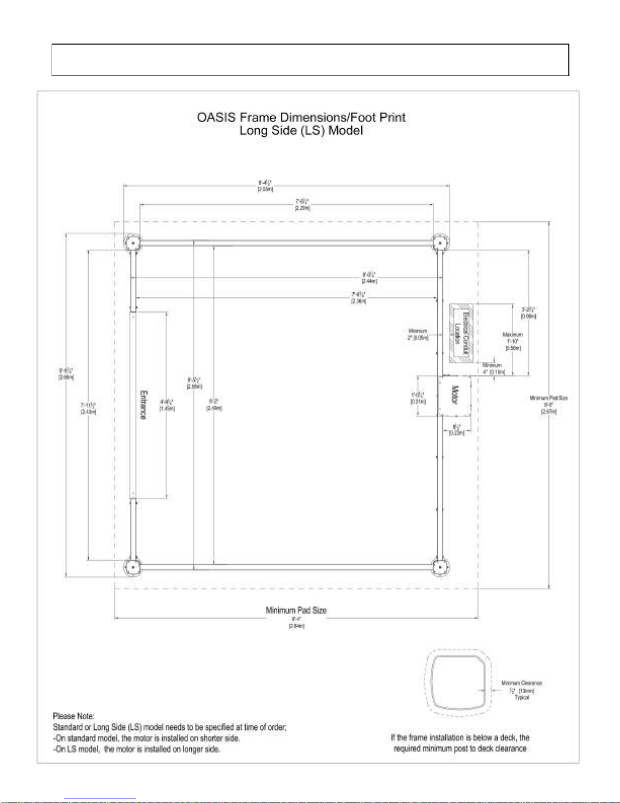
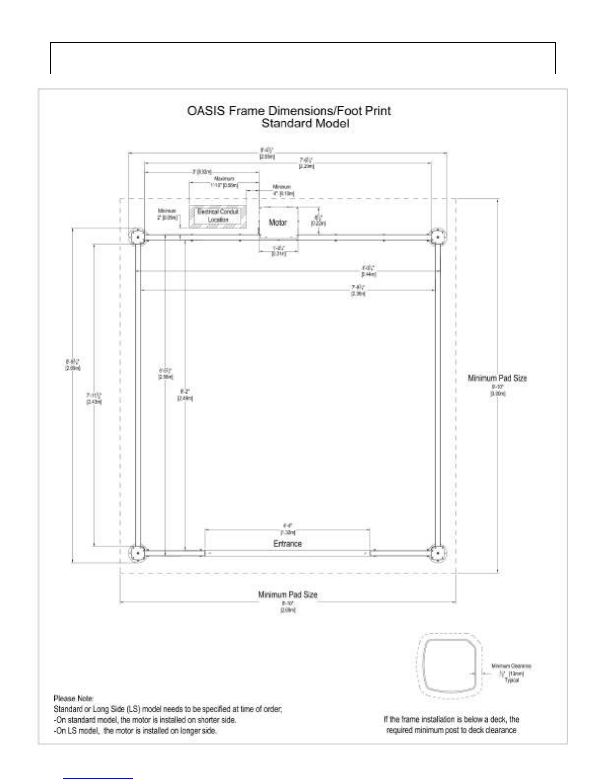
Just like the spa, the Covana requires a solid foundation. The area that the Covana sits on
must be able to support at least 600 lb (272 kg) and must be leveled. All components of the
Covana must be supported by the foundation.
Note: Damage caused by inadequate or improper foundation support is not covered by
the Covana warranty. It is the responsibility of the owner to provide proper foundation.
Foundation recommendation:
1. Engineered wood deck OR concrete pad - 4" (10 cm) thick.
2. Each of the 4 posts on the Covana must be properly anchored to the foundation using at
least one of the pre-drilled holes located at the foot of each post. Use a 1/4” (0.6 cm)
concrete anchor for concrete pads or a 1/4” (0.6 cm) lag bolt for wood foundations of a
minimum of 1-1/4” (3 cm) long.
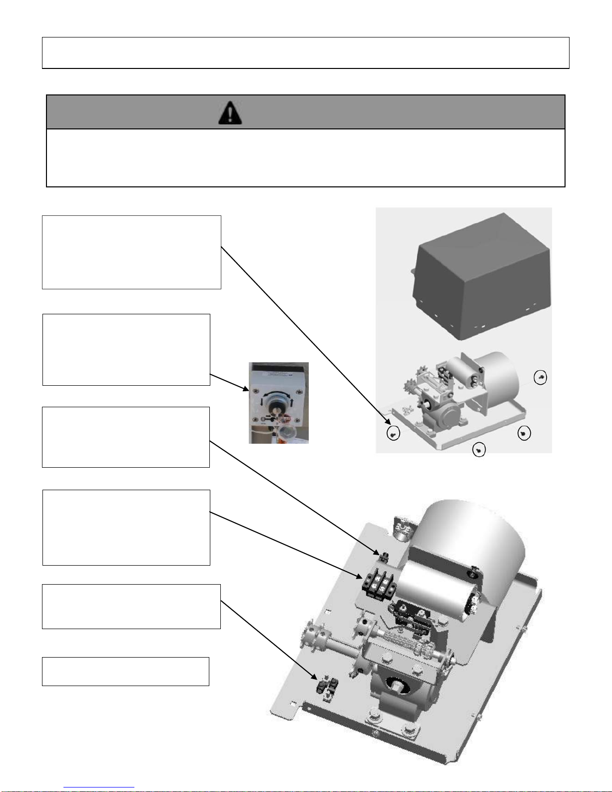
1. The Covana requires a dedicated 115V (North America) or 230V (Europe) permanently
connected (hard wired) power supply.
2. The Covana motor has a dedicated connection for 115V (North America) or 230V
(Europe), please see enclosed connection diagram.
3. The Covana must be installed in accordance to and comply with all applicable local codes
and regulations. All wiring should be installed by a qualified electrician.
4. Wire and conduit should be sized as per local codes and regulations.
The electrical circuit for the Covana must include a suitable ground fault interrupter (GFCI) as
required to comply with codes and regulations.
Required Voltage: 115V (North America) 230V (Europe) (1 hot, 1 neutral, 1 ground)
Required GFCI Breaker: 15A (North America) 10A (Europe) single-pole GFCI breaker, not included
Max Covana current draw: 12 (North America) 6 (Europe) Amps
PREPARING A PROPER FOUNDATION
COVANA ELECTRICAL REQUIREMENTS
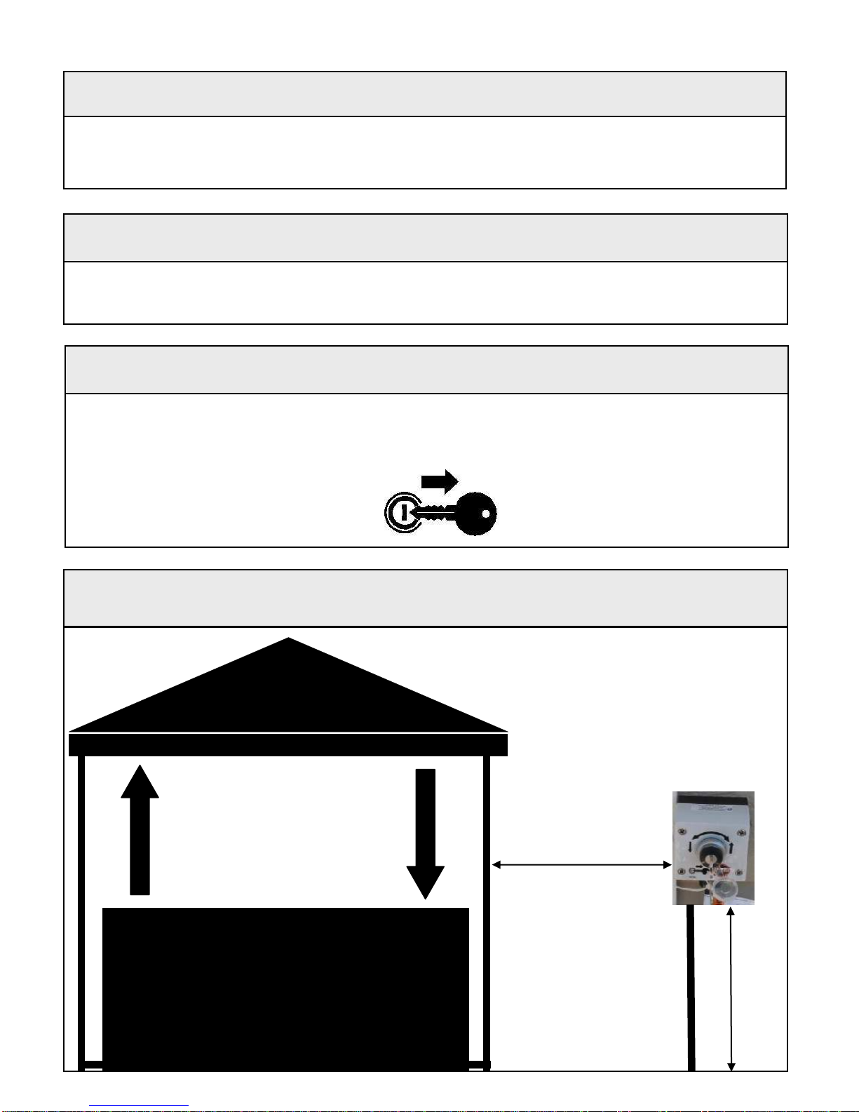
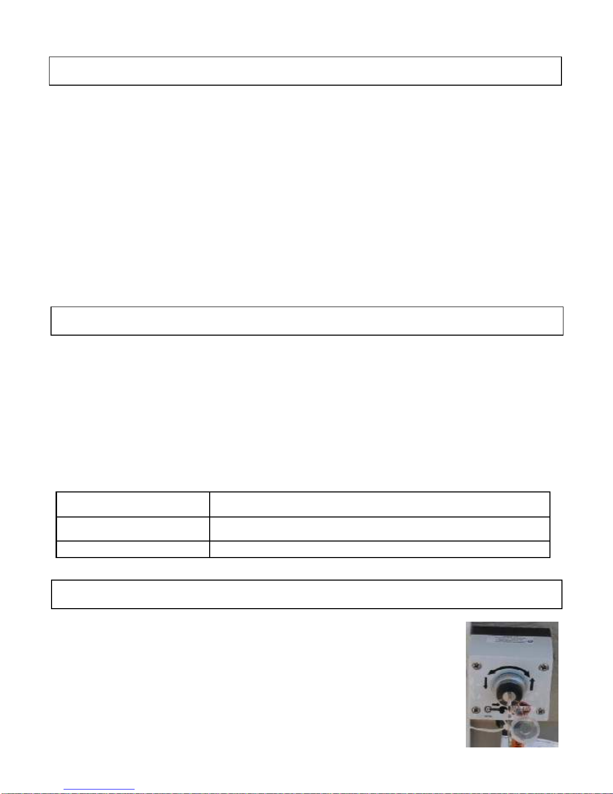
KEY OPERATING INSTRUCTIONS
Turn the key to the right —clockwise to raise the roof.
Turn the key to the left —counterclockwise to lower the roof.
The key will automatically return to center, off position, when released.

7
SIDE ELEVATION DIMENSIONS
Spa height will vary and must be within
these measurements
Minimum is 34" (86 cm)
Maximum is 48" (1.22 m)
Covana maximum travel is
50" (1.27 m)
21" (53 cm)
The maximum elevation height
depends on the height of the spa.
Add spa height to the Covana travel
to determine maximum elevation.
Example:
Spa height + Covana travel which is
50” (1.27 m) = Total elevation

8
FRAME DIMENSIONS AND FOOTPRINT

9
FRAME DIMENSIONS AND FOOTPRINT

10
GROUNDING AND CONNECTION OF POWER SUPPLY
Use the provided terminals to
bond the Covana operator.
Pre-wired key switch with
20’ (7,5 m) of cable in-
cluded. Cable must be run
through a conduit.
Remove the four screws on
the bottom side of the Covana
operator and take the cover
off.
Connect the main 115V
(North America) 230V
(Europe) power to their re-
spective terminals.
Connect the ground cable of
the main power supply to
the provided terminal.
Reinstall the operator cover.
OPERATOR
WARNING
RISK OF INJURY
DISCONNECT OR TURN OFF ALL POWER SUPPLY BEFORE STARTING ANY
INTERVENTION ON THE COVANA.

11
LIMIT SWITCH ADJUSTMENT
Note: The UP & DOWN limits are factory adjusted and there is no need for re-adjustment.
If adjustments are required to ensure the Covana roof does not come into contact with its sur-
roundings while elevating, the UP direction may be decreased. Never change the factory set-
tings of the DOWN limits or increase the UP limit. Failing to do so may result in possible equip-
ment damage and/or injury.
Disconnect or turn power off.
Remove the four screws at the bottom of the operator and take the cover off.
Remove the retaining screw and slide the cam plate from operator frame.
To reduce the travel in the UP direction, turn the UP cam counterclockwise as per ar-
row.
Once the cam is set to the desired position, reinstall the cam plate and make sure that it
is properly inserted in the slot of each cam. NEVER OPERATE THE SYSTEM WITH
THE CAMPLATE REMOVED.
Reinsert the retaining screw to prevent the cam plate from coming out.
Reinstall the operator cover.
Turn the power ON and test the system.
Cam plate and retaining screw
WARNING
RISK OF INJURY
DISCONNECT OR TURN OFF ALL POWER SUPPLY BEFORE STARTING ANY
INTERVENTION ON THE COVANA.

12
MANUAL OPERATION IN CASE OF POWER FAILURE
1. Disconnect or turn power off.
2. Remove the four screws at the bottom of the operator and take the cover off.
3. Use 1/2" or 1.3 cm hexagon socket wrench to operate the operator by turning the input
shaft.
SLOWLY TURN THE SHAFT - STOP IF EXCESS TENSION IS FELT.
NEVER USE A POWER TOOL AS THIS WILL DAMAGE UNIT.
4. Turn the input shaft clockwise to lower the roof and counterclockwise to raise the roof.
5. Reinstall the operator cover.
6. Reconnect or turn power on.
COVER
OPERATOR
WARNING
RISK OF INJURY
DISCONNECT OR TURN OFF ALL POWER SUPPLY BEFORE STARTING ANY
INTERVENTION ON THE COVANA.

13
WIRING & SCHEMATIC DIAGRAM - 120VAC, 60HZ OPERATOR
(NORTH AMERICA)

14
WIRING & SCHEMATIC DIAGRAM - 220VAC, 50HZ OPERATOR
(EUROPE)

15
Scissors /
Retractable blade
knife
Robertson
screwdriver
Hammer
Imperial wrench
(3/8")
7/32” Allen wrench
5. Remove the four (4) sleeve boxes from the crate
and place them in a safe place –two (2) boxes per
side. Be careful not to damage the cover.
6. Remove the parts box, the foams and the seals
package from the crate and place them in a safe
place. Use a hammer to remove the front wood
board by hitting it.
7. Use the Robertson screwdriver to remove the two
(2) screws holding the motor box.
INSTALLATION
REQUIRED TOOLS
UNCRATING
1. Before uncrating the unit, make sure there is no
apparent damage to the crate. In case of suspicious
damage, take photos. If any damage is discovered,
call Covana customer service at 1-877-278-8010.
2. Stand the Covana in the vertical position. Ensure
wind conditions allow for this to be done safely.
3. With the retractable blade knife or scissors, cut and
remove the front cardboard.
4. Use scissors to cut and remove the four (4) cable ties
holding the sleeve boxes –two (2) boxes per side.

16
11. Use the Robertson screwdriver to unscrew the four
(4) screws on the aspenite sheet at the bottom of
the crate –one (1) sheet per side.
12. Remove the aspenite sheet at the bottom of the
crate.
13. Remove the extrusions and the jacks at the bottom
of the crate.
14. With the help of one other person, flip the crate
horizontally on its back side. One (1) person on
each side of the side panel.
8. Use the 3/8'' Imperial wrench to unscrew the screws
holding the bottom of the jack –one (1) screw per
side.
9. Use the 7/32'' Allen key to unscrew the screws
holding the bracket with the jack –one (1) screw per
side.
10. With the help of one other person, remove the motor
end post assembly from the crate. We recommend
one hand under the main frame and one holding the
vertical post. Handle and carry the assembly so that
the posts are straight and parallel. DO NOT TWIST.

17
15. With the retractable blade knife or scissors cut and
remove the top cardboard.
16. If your Covana comes with roller shades, remove
the cardboard cylinder from the holes in the side
panels and place them in a safe place. Be careful
not to damage the cover. Use a hammer to
remove the last wood board in the front of the crate.
17. Use the 3/8'' Imperial wrench to unscrew the four (4)
roof brackets from the side panels –four (4) screws
per side.
18. Use the Robertson screwdriver to unscrew the three
(3) screws holding the side panels to the bottom of
the crate.
19. Remove the side panels by hitting them outward
with a hammer –one (1) panel per side.
ASSEMBLING
1. Attach the foam spacers, using tape, to the top of
the spa near each corner.
2. Place and center the roof of the Covana on the spa,
pay attention to the short side and long side. The
light switch, if a LED light kit option is installed in the
cover, should be placed on the entry side of the spa.
3. If the Covana has the optional lights, perform the
LED light kit installation/ procedure. Instructions are
on the next page.
4. Loosen the lower sleeve retaining bolt, no more
than five turns. Note that the sleeve must be put
back in place between the 2 washers.
Note: It is possible, for ease of installation, to completely
take off the sleeve assembly from the post. To do so,
remove the cap screw located at the top of the sleeve with
a 7/32” Allen wrench.
20. With the help of one other person, lift up the cover
by holding it in the middle of the edges and place it
on the spa.
***WARNING***
When handling the cover, make sure to support
the complete assembly with your hands (both
inner shell and outer shell must be supported).
DO NOT GRAB THE OUTER SHELL EDGE
ALONE TO LIFT THE COVER, THIS WOULD
DAMAGE THE OUTER SHELL CORNER.
Note: The cover alone is approximately 220 lb. You
might want to split the cover in two parts if you need
to move it where space is limited. To do so, gently
pull off the outer shell.

18
12. Jack lock bracket located at the bottom of non-motor
side jacks can now be safely removed.
5. Lay the sleeves in a safe location, preferably
horizontal on a soft surface.
6. Position the motor and two post assembly in place,
usually to the rear of the spa. Slide the jacks against
the cover’s corners.
7. Slide the drive shafts over the square shaft located
at the bottom of both motor side jacks.
8. For the non-motor side jacks, hold the jack vertical
and in line with the drive shaft (square tube). Using
a 3/4” wrench on the square shaft at the bottom of
the jack, make fine adjustments so it is in line with
the drive shaft and carefully slide the square shaft of
the jack into the drive shaft.
9. Install the aluminum U frame over the drive shaft
and post bracket. Fasten in place using hardware
provided, 4 bolts + 4 nuts + 8 washers.
10. Perform steps 8 to 9 on the second non-motor side
jack.
11. Assemble and install the front frame with the cut-out
for the steps.
LIGHTING INSTALLATION
(OPTIONAL FEATURE)
IMPORTANT
Determine the corner of the Covana that is likely to
receive the most sun, generally south is best; ensure
there are no interfering objects.
Take note that the battery is shipped inside the
hardware kit.
The battery is installed on the same short side as the
on/off switch.
Take note the switch should be positioned at the
entry side of the spa.
Ensure that all the hardware securing the outer shell
to the inner shell is removed.
Lights should operate for about 4 hours on a full
charge.
1. Lift the outer shell on the side where the battery is
located to access the connections of the Solar Panel.
Do not lift more than 16” (40 cm).
2. Install the battery in its foam support (located left of
the on/off switch inside the top.) Make sure to
correctly connect the positive “+” and negative
“-” wires to the proper battery terminal. Each wire is
clearly labeled accordingly.

19
3. Outside installation –Remove the solar panel from
the box located inside the top of the Covana.
Connect the solar panel to the lighting wire harness
and place the wires and panel to the corner of the
Covana where the panel will be mounted.
4. Show Room installation —Determine the best
corner to locate the charger connection; generally the
back side would be less visible. Connect the charger
on the outside of the cover. Hide the cord of the solar
panel inside the unit so it appears to be installed.
Note: The charger is only to be used in a show room
and is not designed or intended to be used outdoors.
5. Lower the outer shell back over the inner shell
taking care to ensure the wires are not pinched and
are placed in the slit of the outer shell corner.
6. Insert the suction cups in the panel; then remove the
protective layer from the foam tape on the back
suction cups. Carefully place the panel 3” (7.5 cm)
up from the corner and center the panel on the ridge
of the roof.
The blue light MUST be located at the top of the
solar panel. Apply pressure and rock the panel
back and forth to ensure proper adhesion.
7. If using the solar panel, check to ensure the panel is
working –blue flashing light.
8. Continue with final installation.

20
7. Verify that all four corner brackets are positioned at
the same height.
8. Then, using the self drilling screws, insert four
screws per post.
IMPORTANT: Make sure there is no gap between the
sleeve and the bracket.
Finish by tightening the four M6 screws on the cover.
IMPORTANT: There should not be any gap between the
cover and the sleeve.
FINAL ASSEMBLY
AT THIS POINT, THE ELECTRICAL POWER SUPPLY
MUST BE CONNECTED TO CONTINUE THE
INSTALLATION. THIS WILL ENSURE THE PROPER
SETTINGS CAN BE MADE.
1. Mount key box as per instructions on page 4.
2. Test system by turning key clockwise to elevate
posts. Continue holding key until motor stops
automatically and posts are fully elevated.
3. Turn the key counterclockwise to lower the jacks,
continue holding key until motor stops automatically
and posts are fully lowered. Measure from the foot to
the top of the jack. Maximum height should be
51.5” (1.28 m).
4. Reinstall the post sleeves. Ensure the all-weather kit
is fully slid down to make contact with the outer
sleeve. Ensure that one washer is on the inside and
the other washer is on the outside at the bottom of
the posts.
5. Make sure the cover is centered and leveled on the
hot tub.
6. Install corner brackets at each corner. Fasten the
bracket to the cover with the M6 first. Do not tighten
completely.
Other manuals for OASIS
4
Table of contents
Other COVANA Hot Tub manuals

COVANA
COVANA HORIZON User manual

COVANA
COVANA LEGEND User manual

COVANA
COVANA C-HOR User manual

COVANA
COVANA OASIS User manual

COVANA
COVANA OASIS User manual

COVANA
COVANA Evolution User manual

COVANA
COVANA Evolution User manual

COVANA
COVANA LEGEND User manual

COVANA
COVANA Evolution Series User manual

COVANA
COVANA LEGEND User manual
Popular Hot Tub manuals by other brands

CalderaSpas
CalderaSpas CalderaSpas Utopia Series owner's manual

anko
anko SS-601A user manual

CalderaSpas
CalderaSpas CANTABRIA owner's manual

Dimension One Spas
Dimension One Spas HYDRO SPORT Installation and owner's guide

Bestway
Bestway Lay-Z-Spa Maldives HydroJet Pro manual

Dimension One Spas
Dimension One Spas Nautilus Specifications