COVANA LEGEND User manual

1 TABLE OF CONTENTS INSTALLATION MANUAL
2019
Revision 2
2019-06-13
C.A. 232868

2 TABLE OF CONTENTSINSTALLATION MANUAL
TABLE OF CONTENTS
TABLE OF CONTENTS .............................................................................................................................................2
SAFETY......................................................................................................................................................................4
Safety information...................................................................................................................................................4
Avoiding the risk of electrocution ............................................................................................................................5
LABELLING ...............................................................................................................................................................7
GLOSSARY................................................................................................................................................................9
HARDWARE IDENTIFICATION TABLE .................................................................................................................15
INSTALLATION PREPARATION ............................................................................................................................17
Location considerations ........................................................................................................................................17
Foundation preparation.........................................................................................................................................18
INSTALLATION .......................................................................................................................................................19
Uncrating ..............................................................................................................................................................19
Cover assembly ....................................................................................................................................................23
Lifting mechanism assembly ................................................................................................................................36
ELECTRICAL HOOK-UP .........................................................................................................................................43
Avoiding the risk of electrocution..........................................................................................................................43
AC Control box .....................................................................................................................................................44
Optional Emergency battery backup ....................................................................................................................44
Battery and solar panel.........................................................................................................................................45
Testing the COVANA cover..................................................................................................................................46
Wiper brackets installation....................................................................................................................................47
Seal application ....................................................................................................................................................48
Upper limit reset of posts ......................................................................................................................................50
APPENDIX ...............................................................................................................................................................51
TECHNICAL SPECIFICATIONS..............................................................................................................................54
Side elevations .....................................................................................................................................................54
Frame and footprint ..............................................................................................................................................55
Electrical specifications (For AC-operated model) ...............................................................................................55
Electrical specifications (For Battery-operated model).........................................................................................56
Operating limitations .............................................................................................................................................57
General specifications ..........................................................................................................................................57

INSTALLATION MANUAL TABLE OF CONTENTS 3
Battery charging (For Battery-operated models and Emergency-Battery backup only).......................................58
TROUBLESHOOTING .............................................................................................................................................59
INSTALLATION CHECKLIST (Customer copy)....................................................................................................61
INSTALLATION CHECKLIST (Installer copy).......................................................................................................63

4 SAFETY INSTALLATION MANUAL
SAFETY
IMPORTANT SAFETY INSTRUCTIONS
SAVE THESE SAFETY INSTRUCTIONS AND
REVIEW THEM REGULARLY.
READ AND FOLLOW ALL INSTRUCTIONS
Safety information
The COVANA cover was designed, tested and
certified to be installed over a residential swim spa
and under important installation instructions issued by
COVANA. Any other type of usage will void the
warranty and product certification.
The extra load maximum weight provided in the
specification section of this manual is a provision for
environmental outcomes, such as some snow or
damp leaves that could accumulate on the cover, that
are evenly distributed on the surface of the cover.
The COVANA cover was not designed to support any
additional load or people walking or standing on it.
Failure to observe this instruction will void the
warranty and product certification.
The power safety cover meets ASTM F1346-91
requirements.
DANGER
To reduce the risk of injury, do not allow children
to use this product unless they are supervised at
all times.
Failure to follow all instructions may result in
injury or even death.
Do not allow people to climb or walk on the cover
at anytime.
Do not allow children to have access to the
COVANA cover without supervision.
Never operate the COVANA cover until all people
and objects are out of the spa.
WARNING
Be sure to keep the key switch and the key out of
the reach of children.
Do not put any type of fabric or plastic sheet, such
as a tarpaulin, on the COVANA cover. This could
overheat the cover and result in the deformation
or delamination of the cover.
Inspect the cover periodically. It should raise
smoothly and evenly. Contact your COVANA
dealer if any unusual mechanical sound is heard
during use.
Never use any type of pressure washer or buffer
to clean any surface of the COVANA cover. This
could result in premature wear or damage.
DO
Remove the control key after operating the
COVANA cover. Store the key in a secure
location when not in use. Users must bring the
control key in the spa with them to prevent the
unauthorized operation of the cover.
Never leave the key in the key switch.
Check the cover frequently for signs of
deterioration.
Have any repairs, adjustments or mechanical
work performed by your authorized COVANA
dealer as soon as possible should you notice a
malfunction.
Close the cover when not in use or if the swim spa
is not being monitored.
A COVANA cover should only be operated by an
adult.
This appliance can be used by children aged 8
years and above and persons with reduced
physical, sensory or mental capabilities or lack of
experience and knowledge ONLY if they are
supervised or have received instructions
regarding safe use of the cover. Children must not
play with the appliance. Cleaning and user
maintenance must not be performed by children
without supervision.
DO NOT
Operate the unit before all the mechanical and
electrical connections are completed.
Step on or stack anything on the COVANA control
box or AC control box.
Operate the COVANA cover while someone is in
the swim spa.
Climb, walk or stand on the COVANA cover at
any time.
Leave the COVANA cover open for more than 12
hours. This could cause the cover to warp
overtime.
Converge or directly reflect sunlight on the cover.
This could cause permanent damage.
Wash the cover with harsh chemicals or cleaners.

INSTALLATION MANUAL SAFETY 5
Use a pressure washer to clean any component
of the COVANA cover. This could result in
premature wear or damage.
CAUTION
Be sure to follow all instructions in this manual
and use only COVANA-approved accessories
and tools.
Do not roll the COVANA cover onto its side or
slide it on its side. This will damage the siding.
After removing a part, always place it in a safe
place on a clean and level surface to ensure
proper functionality.
All four posts of the COVANA cover must be
properly anchored to the swim spa frame using
the tub mounting brackets and arms.
This product mainly contains steel, plastic,
copper (Cu), fiberglass, foam and aluminum (Al).
Please recycle them properly.
For the battery-operated option or the emergency
backup option, both are powered by a
rechargeable sealed lead acid battery. Please
recycle it properly.
Avoiding the risk of electrocution
ELECTRICAL DANGER
Failure to comply with these instructions may
result in death by electrocution or serious injury.
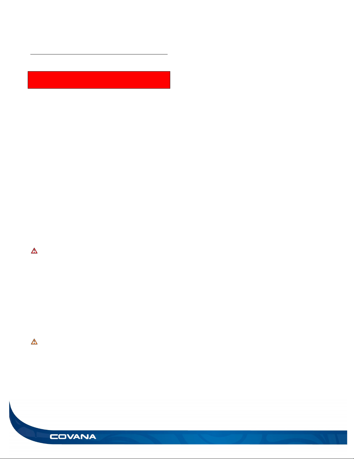
Disconnect or turn off and secure all power
supplies before starting any intervention on the
COVANA cover.
For AC operated model: A disconnect mean
needs to be incorporated into the fixed wiring at
the time of installation. This mean must be
accessible to the user or service technician to turn
the power off for future maintenance or repair.
Always have a licenced electrician contractor
perform any electrical maintenance or repairs on
the COVANA cover. The wiring must comply with
all applicable electrical codes and regulations.
For AC-operated models: The COVANA operator
must be connected to a circuit that is protected by
a dedicated ground fault circuit interrupter (GFCI)
that complies with all applicable local electrical
codes and regulations.
Install the COVANA cover in such a way that
drainage directs water away from the electrical
components and base mechanical components.
Do not connect any auxiliary components to the
electrical system of the COVANA cover unless
they have been approved by COVANA.
Replace electrical components with original
components provided or approved by COVANA.
Ask your dealer for replacement parts.
To reduce the risk of electric shock, replace all
damaged cables immediately. Failure to do so
may result in death or serious personal injury due
to electrocution.
Do not bury any electrical cables. A buried cable
may result in death or serious personal injury due
to electrocution if direct burial-type cable is not
used, or if improper digging occurs.
ELECTRICAL WARNING
for AC-operated model
To reduce the risk of electric shock, the green-
colored terminal or the terminal marked “g,” “gr,”
“ground,” “grounding” or with a ⏚symbol located
inside the supply terminal box or compartment
must be connected to the grounding means
provided in the electric supply service panel with
a continuous copper wire equivalent in size to the
circuit conductors supplying the equipment.
One bonding lug is installed on one non-motor
jack. To reduce the risk of electric shock, connect
the COVANA cover bounding lug to the local
common bonding grid in the area. Use terminals
with an insulated or bare copper conductor no
smaller than No. 6 AWG (4.11 mm).
All field-installed metal components, such as
rails, ladders, drains or other similar hardware,
within 10 ft (3 m) of the swim spa must be bonded
to the equipment grounding bus with copper
conductors no smaller than No. 6 AWG (4.11
mm). (NEC art. 680.)
WARNING REGARDING DRUG OR
ALCOHOL USE
The use of drugs or alcohol while operating the
COVANA cover is strictly prohibited. The
impairment of judgment, vision or hearing might
affect the safety of other people or result in death.

6 SAFETY INSTALLATION MANUAL
WARNING REGARDING
MODIFICATIONS TO THE COVANA
COVER
Any modifications to the COVANA cover, such as
mechanical, electrical or aesthetic ones, may
cause the cover to operate in an unwanted or
dangerous way. Furthermore, these
modifications might void the warranty and
certification.
The COVANA cover was designed, tested and
certified for the sole purpose of covering and
securing a spa. Any installation that differs in
whole or in part from this purpose will void the
warranty and certification.
SAVE THESE INSTRUCTIONS

INSTALLATION MANUAL LABELLING 7
LABELLING
WARNING
♦Removing any labels from the COVANA cover will void product certification. All labels should
always remain visible. It is the owners’ responsibility to ensure these labels are always visible and
should never be removed
Risk of electrocution warning,
located on the AC control box.
(For AC-operated models only)
Key operating diagram, located
on the key switch.
Drowning risk, located on all four sides of the COVANA cover
Specification label, located on the white control box
Note: This label provides the serial number
(For Battery-operated models only)
Specification label, located on the AC control box
Note: This label provides the serial number
(For AC-operated models only, North America Only)
Specification label, located on the AC control box
Note: This label provides the serial number
(For AC operated model only, European Only)

8 LABELLING INSTALLATION MANUAL
Key switch warning, located on the key switch cable
Electrical information, located on the key switch cable
Do not step on cover label, located of end C-Channels of the COVANA cover
Do not step symbol,
located on AC control box
(For AC operated model only)
Battery specification label, located on the
back of the battery pack.
Center label, located on 94 9/16in (240 cm) C-Channel
(remove after installation)
Top label, located on I-Beams and Escape hatch opening
(Hidden when assembled)
Maintenance information, located
on one of the C-Channels.

INSTALLATION MANUAL GLOSSARY 9
GLOSSARY
Part Figure Function
All-weather seal
The all-weather seal will help protect sleeves from damage
due to weather.
AC control box
(AC-operated model only)
Figure 2
The AC control box powers and controls
the lifting
mechanism of the COVANA cover.
Battery pack
(Battery-
operated model
and battery backup only)
The battery pack is a sealed case where the two 12 V
batteries are located. The harness that will connect to the
charger and control box is on its right.
Binding block The binding block is used during installation to tighten the I-
beams with the panels.
C-channel The C-channel is the outer frame of the cover.
Figure 4
Figure 1
Figure 5
Figure 3

10 GLOSSARY INSTALLATION MANUAL
Control box
(for battery-operated
model only)
The control box manages the movement of the unit.
Control box housing
(for battery-operated
model only)
The control box contains all the electronic parts of the
COVANA.
Contour seal The contour seal ensures uniform contact between the cover
and the swim spa. It prevents excessive water and other
contaminants from entering the swim spa. It also reduces
heat loss.
Contour seal
connector
The seal connector is used to link both ends of the seal.
Contour seal
installation clip
Contour seal installation clips are used during the installation
process to ensure the seal is installed properly.
Corner bracket The corner brackets link the C-channels on the side to the
ones in front and back.
Figure 11
Figure 6
Figure 7
Figure 9
Figure 10
Figure 8

INSTALLATION MANUAL GLOSSARY 11
Corner cover The corner cover is an aesthetic aluminum grid fixed to the
corner bracket.
Drive shaft
The drive shaft transmits the power between the jack
assemblies.
Escape hatch
The escape hatch is a removable panel and part of the cover.
Refer to Using the escape hatch section.
Hammer block The hammer block is a piece of plastic or wood used during
the installation to hit on the panels without causing damage.
I-beam The I-beams are the aluminum extrusions installed between
the panels.
Foam spacer The installation foam is used during the installation process
to protect the swim spa from direct contact with the cover.
Figure 12
Figure 13
Figure 14
Figure 16
Figure 17
Figure 15

12 GLOSSARY INSTALLATION MANUAL
I to C connection
plate (long)
The long I-to-C connection plate makes the link between I-
beam, posts and sleeves.
l to C connection
plate (short)
The short I-to-C connection plate makes the link between I-
beam and C-channels.
Jack (motor and non-
motor)
Figure 20
The jack allows the cover to go up and down.
I to C spacer The I to C spacer is used to prevent over tightening of the I
to C connection plates.
Key switch
The key switch is used to operate the COVANA cover.
Mount bracket arm
This mount bracket arm will link the sleeves and swim spa
together.
Figure 21
Figure 23
Figure 22
Figure 18
Figure 19

INSTALLATION MANUAL GLOSSARY 13
Post mount bracket
or
Dual side bracket
(optional)
(optional)
Figure 24
Post mount bracket links the sleeves and posts to the cover.
Dual side brackets are used for higher or lower swim spas.
Sleeve
The sleeve is an aluminum case for the lifting mechanism.
Support bracket The support bracket strengthens the joint between the center
C-channel to the C-channel on either side. It clips and is
screwed on the top and bottom.
Top plate
The top plate is a
cover that is installed on the sleeve
assembly. It protects the lifting mechanism from debris.
Tub mount bracket
This bracket links the cover to the swim spa. There is one tub
mount bracket located at the top of the outer sleeve for every
post. If the swim spa is 54” (137 cm) high and under, two of
these brackets are mounted on the swim spa per post.
Figure 25
Figure 28
Figure 26
Figure 27

14 GLOSSARY INSTALLATION MANUAL
Extended tub mount
bracket (Optional)
The extended tub mount bracket is optional for swim spas
over 54” (137 cm). This bracket will replace the upper tub
mount bracket on the swim spa and will allow for better
mounting options.
U-frame The U-frames protect the drive shaft. They are fastened to
the bottom of the posts.
Wiper bracket The wiper bracket is adhered under the I-beams. This part is
required to ensure the waterproofing of the COVANA cover.
Figure 30
Figure 31
Figure 29

INSTALLATION MANUAL HARDWARE IDENTIFICATION TABLE 15
HARDWARE IDENTIFICATION TABLE
Quantity
Visual representation
Description
9x
5/16-18 x 2” This hexagonal
bolt is used for the lower U-
frame assembly.
17x
(33x for model
with long
support
bracket
approx.
42’’[1,066 mm])
10-24 x 1/2” thread cutting
screw. Used on the panel
assembly.
25x
#8 x 1/2” Self-tapping screw.
Used to fasten the corner
brackets.
9x
#8 x1/2” Self-drilling screw.
Used to fasten the top plates.
17x
1/4-20 x 3/4” Carriage bolt.
Used for fastening the sleeve
to the post mount bracket
assemblies.
21x
1/4-20 x 5/8” Carriage bolt.
Used for fastening the I-beam
assemblies. Note: 13x for
models 12’ to 15’.
50x
1/4-20 x 1” Button hex drive
bolt. Used for mount brackets
and roof assemblies.

16 INSTALLATION MANUAL
33x
#10-12 x 3/4” Screws used for
anchoring the tub mount
brackets.
33x
1/4” Lock washer used for the
mount brackets and sleeve
assemblies.
33x
1/4” Flat stainless steel washer
used for mount brackets and
cover assembly.
70x
1/4-20 Hex nut. Used for
sleeve and mount brackets
assemblies. Also used for I-
beam assemblies. Note: 62x
for models from 12’ to 15’.
9x
5/16-18 Nylon insert locknut.
Used for the U-frame
assemblies.
1x
5/32” Hex key. Used for
fastening the 1/4-20 x 1” Button
hex drive bolts.
1x
#2 x 6” Robertson drive bit.
1x
5/32” drill bit used to drill holes
on the support bracket.

INSTALLATION MANUAL INSTALLATION PREPARATION 17
INSTALLATION
PREPARATION
To ensure the safe use of the COVANA cover, it must
be installed on a properly prepared surface. It is
important to adequately prepare the foundation and
carefully read the following recommendations.
Location considerations
Ensure the future location of the COVANA cover
is not subject to falling water or debrisfrom
another rooftop.
Ensure that the base of the cover is not in a flood
zone. Any damage caused by flooding or water
accumulation will not be covered under the
warranty.
Ensure that there are no obstacles, such as
branches or electrical power lines, in the
operating range of the COVANA cover.
Refer to Technical specifications section for
dimensions of cover.
Ensure there is safe access to the swim spa, free
of obstacles or debris.
All the base components of the COVANA cover
must be supported by the foundation.
Do not converge or directly reflect sunlight on the
cover. This could cause permanent damage (i.e.:
reflection by a window).
Ensure the COVANA cover is installed on a clean
surface free of any vegetation, such as grass,
branches or roots, or mineral contaminants, such
as rocks, dust or sand.
The key switch must be permanently mounted
and located 5’ (1.5 m) away from the swim spa
and 5’ (1.5 m) above the deck or ground level.
Ensure the user has a clear view of the COVANA
cover when operating it. Furthermore, the key
switch terminal should be located in a place
where no water or debris could fall on it from
another rooftop (Figure 32).
WARNING
Failure to permanently install the key switch as
indicated could cause serious injury or even
death and void the warranty and certification.
Only the proper installation of the key switch
combined with the suggested procedures and
caution will reduce such risks.
Do not place the cover in an area prone to snow
accumulation or water runoff.
DANGER
Failure to properly install the key switch according
to these instructions could result in injury or even
death.
Figure 32
1.5 metres
1.5 metres

18 INSTALLATION PREPARATION INSTALLATION MANUAL
Foundation preparation
The COVANA cover requires a clean, flat and
level surface, such as an engineered wood deck
or a concrete slab.
Each of the four jacks of the COVANA cover must
be properly fastened to the swim spa frame. It is
the installer’s responsibility to ensure the
COVANA cover is properly fastened and in a safe
manner.
Just like the swim spa, the COVANA cover
requires a solid foundation. The foundation for the
COVANA cover must be able to support at least
1,000 lb (454 kg).
The foundation must be levelled with a maximum
tolerance of 1” (2.5 cm) over a 153” (3.89 m)
diagonal section and 112” (2.84 m) by 104 1/4”
(2.65 m) rectangle (Figure 33). The annual
variation in levelness for the same diagonal
section cannot exceed 1/4” (6 mm).
A path at least 1” wide all around the
perimeter of the swim spa is necessary to
properly install the seal.
CAUTION
Damage caused by inadequate foundation
construction is not covered by the COVANA
warranty. It is the responsibility of the owner to
provide a proper foundation.
Failure to follow these guidelines might cause
permanent damage or the improper functioning of
the COVANA cover. Such damage might not be
covered by the warranty.
Figure 33
112” (2.84 m)
104 ¼” (2.65 m)

INSTALLATION MANUAL INSTALLATION 19
INSTALLATION
Required tools for complete
installation
Scissors or a retractable utility knife
Robertson screwdriver
Rubber mallet
Hammer
Phillips screwdriver
2x 50’ (15 m) Ratchet straps
CAUTION
The COVANA cover should be installed by a
certified COVANA installer. Having the COVANA
cover installed by someone who is not certified will
void the warranty. Ask your local COVANA dealer
for information on certified installers.
7/16’’ (11 mm) socket wrench and spanner
1/2" (13 mm) socket wrench and spanner
5/32’’ (4 mm) Allen key (Supplied)
26’ (8 m) measuring tape
SAE or metric Socket kit
48” (122 cm) level
Stepladder
Uncrating
1) Before uncrating the unit, ensure there is no
visible damage to the crate. In case of any
suspicious damage, take pictures first. If any
damage is discovered, please call the COVANA
customer service immediately.
2) Stand the crate in the vertical position. Ensure
wind conditions allow for this to be done safely.
3) Use the sheet metal cutter to cut and remove the
metal strap around the crate.
4) Unscrew the #8-10 x 1.5” Robertson screws
holding the front cover – 5 screws per side and 3
on the top. You might need a stepladder to reach
the top screws. (Figure 34)
5) Remove the front cover and discard. (Figure 34)
6) Remove the paper sheet covering parts inside the
crate.
7) Unscrew the two Robertson #8-10 x 1.5” screws
holding the top of the sleeves – four sleeves: eight
screws in total. (Figure 35)
8) Remove all four sleeve assemblies.
Figure 34
Figure 35
NOTE: For models with long support bracket
(approx. 42’’[1066mm]), remove the joint bracket
from inside the sleeve

20 INSTALLATION INSTALLATION MANUAL
9) Remove all boxes above the jack box, place them
in a safe place (Figure 36).
Note: All the hardware, brackets and other parts are
located in these boxes.
10) Unscrew the Robertson #8-10 x 1.5” screws
holding the jack box – four screws per side: two
screws at the top, two screws at the bottom. The
blue circle represents the screw holding the crate,
the jack box and the binding blocks. This screw is
only on the left side of the crate. Unscrew it as
well. (Figure 37)
Figure 36
Figure 37
Jack box
Other manuals for LEGEND
5
Table of contents
Other COVANA Hot Tub manuals

COVANA
COVANA OASIS User manual

COVANA
COVANA LEGEND User manual

COVANA
COVANA C-HOR User manual

COVANA
COVANA LEGEND User manual

COVANA
COVANA OASIS User manual

COVANA
COVANA Evolution User manual

COVANA
COVANA LEGEND User manual

COVANA
COVANA Evolution User manual

COVANA
COVANA HORIZON User manual

COVANA
COVANA Evolution Series User manual
Popular Hot Tub manuals by other brands

Jacuzzi
Jacuzzi J-200 Series owner's manual

Aquatic
Aquatic LUXEAIR 22 AI22lux6636 Specification sheet

Aquapeutics
Aquapeutics Mazatlan installation manual

Aquatic
Aquatic SOUTH PADRE ai6636R Specification sheet

Marquis
Marquis Crown Summit owner's manual

Penner Bathing Spas
Penner Bathing Spas 770010-1 Operation & maintenance manual