INSTALLATION MANUAL SAFETY 5
Converge or directly reflect sunlight on the
cover. This could cause permanent damage.
Wash the cover with harsh chemicals or
cleaners.
Use a pressure washer to clean any component
of the COVANA cover. This could result in
premature wear or damage.
Use an extension cord to connect the COVANA
cover to its power source. The cord may not be
properly grounded, and the connection is a
shock hazard. An extension cord may cause a
voltage drop, which would cause the motor to
overheat.
CAUTION
Be sure to follow all the instructions in this
manual and only use COVANA-approved
accessories and tools.
Do not roll the COVANA cover onto its side or
slide it on its side. This will damage the siding.
After removing any part, always place it in a
safe place on a clean and level surface to
ensure proper functionality.
For anchoring models: Both posts of the
COVANA cover must be properly anchored to
the foundation using the anchoring holes
located at the foot of each post.
For tub-mount models: Both posts of the
COVANA cover must be properly anchored to
the hot tub frame using the tub-mount brackets
and arms.
This product mainly contains steel, fiberglass,
foam, copper (Cu) and die-cast aluminum (Al).
The gearbox contains oil and other materials.
Please recycle them properly.
Both the up and down limit switches are pre-
adjusted at the factory. The down-limit switch
should never be readjusted. The up-limit switch
should be readjusted only to reduce the
maximum height of the cover to avoid possible
contact with its surroundings. Please refer to
the Limit Switch Adjustment section in this
manual before making any adjustments. An
improper adjustment can result in damage to
the drive system and/or cover.
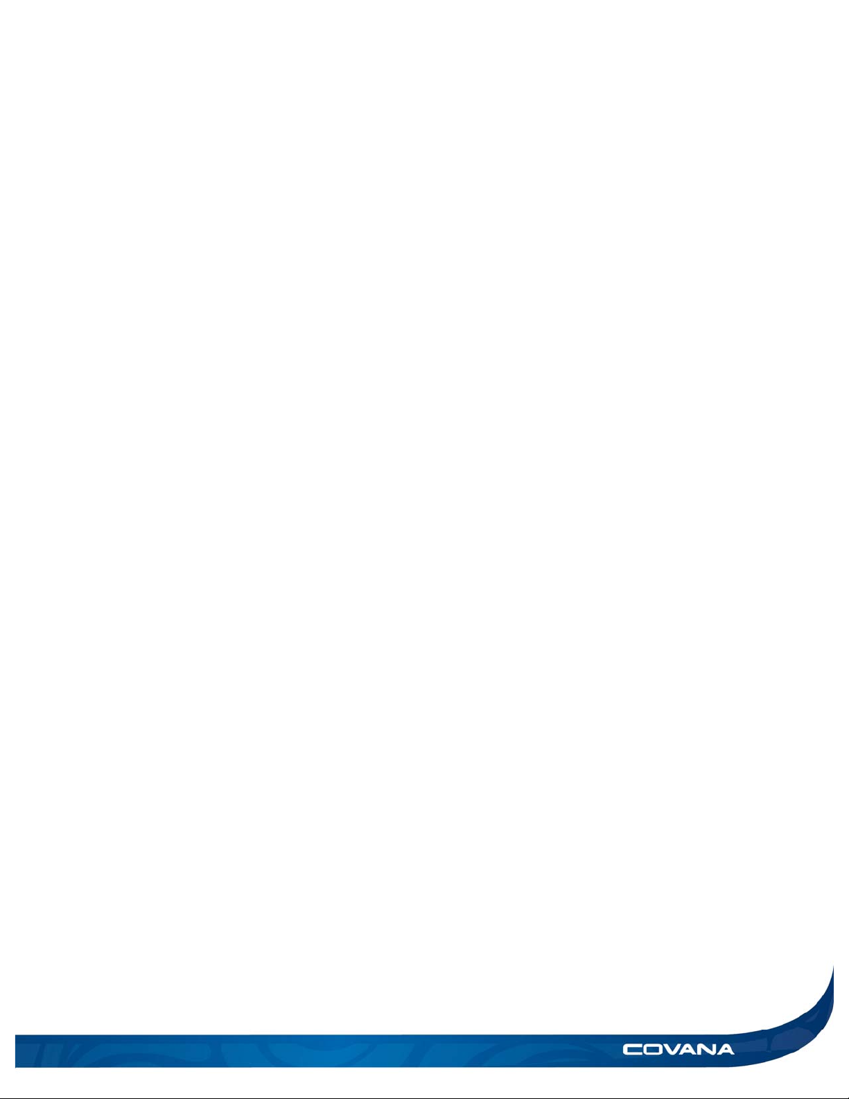
Avoiding the risk of electrocution
ELECTRICAL DANGER
Failure to comply with these instructions may
result in serious injury or death by electrocution.
Disconnect or turn off and secure all power
supplies before starting any maintenance on
the COVANA cover.
A disconnecting mean needs to be
incorporated into the fixed wiring at the time of
installation. This device must be accessible to
the user or service technician to turn the power
off for future maintenance or repair
Always have a licensed electrical contractor
perform any electrical maintenance or repairs
on the COVANA cover. Wiring must comply
with all applicable local electrical codes and
regulations.
The COVANA operator must be connected to a
circuit that is protected by a dedicated ground
fault circuit interrupter (GFCI) that complies
with all applicable local electrical codes and
regulations.
Install the COVANA cover in such a way that
drainage directs water away from all electrical
and base mechanical components.
Do not connect any auxiliary components to the
electrical system of the COVANA cover unless
they have been approved by COVANA.
Replace electrical components with original
components provided or approved by
COVANA. Ask your dealer for replacement
parts.
To reduce the risk of electrical shock, replace
all damaged electrical cables immediately.
Failure to do so may result in death or serious
personal injury due to electrocution.
Do not bury any electricalcables. A buried cable
may result in death or serious personal injury
due to electrocution if direct burial-type cable is
not used, or if improper digging occurs.
ELECTRICAL WARNING
To reduce the risk of electric shock, the green-
colored terminal or the terminal marked “g,”
“gr,” “ground,” “grounding” or with a ⏚symbol
that is located inside the supply terminal box or
compartment must be connected to the
grounding means provided in the electric
supply service panel with a continuous copper
wire equivalent in size to the circuit conductors
supplying the equipment.


 owner's manual")