Covid EHB-120 User manual

EHB-120
USER MANUAL v1.0
1723 W. 4th Street Tempe Arizona 85281
P: 800.638.6104 | F: 480.966.6728 | E: sales@covid.com | www.covid.com
HDBase-T Slim-Line Transmitter/Receiver Set
with Audio De-Embedding
Receiver
Receiver Back
Transmitter
Transmitter Back

EHB-120
USER MANUAL v1.0
1723 W. 4th Street Tempe Arizona 85281
P: 800.638.6104 | F: 480.966.6728 | E: sales@covid.com | www.covid.com Page 1
Table of Contents
Introduction . . . . . . . . . . . . . . . . . . . . . . . . . . . . . . . . . . . . . . . . . . . . . . . . . . . . . . . . . . . . . . . . . . . . . . . . . . . . . . . . . . . . . . . 2
Features ...........................................................................................2
Package............................................................................................2
Specications ......................................................................................3
Operation Controls & Functions ..................................................................4-5
Application Examples ............................................................................6-7
Preparing RS232 Cable ...........................................................................7-8
RS 232 Firmware Update.........................................................................9-12
RS 232 Application Example .......................................................................13
Warranty ......................................................................................... 14
Safety Information ................................................................................14

EHB-120
USER MANUAL v1.0
1723 W. 4th Street Tempe Arizona 85281
P: 800.638.6104 | F: 480.966.6728 | E: sales@covid.com | www.covid.com Page 2
Introduction
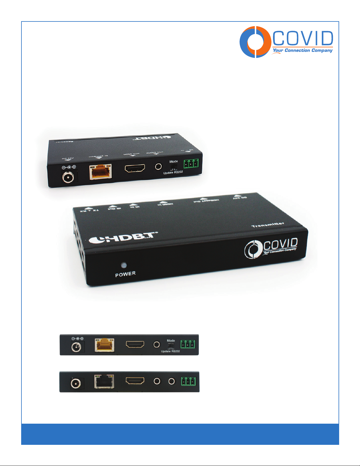
This HDBaseT transmitter/receiver set can extend HDMI over a single CAT5e/6/6A cable. This product
oers Bi-directional IR, RS-232 and Bi-directional PoC making any professional A/V set-up more
ecient and easy to use. Uncompressed video and audio can be transmitted up to 230ft/70m. This
design of HDBaseT™ technology allows for full usage of HDMI and controls over CAT5e/6/6A cable. The
receiver provides de-embedded audio for L/R audio output.
Features
•HDMI 1.4b, HDCP 2.2 and 1.4
•Video resolutions up to 4K2K@30Hz
•Audio up to 7.1 channels of High Denition audio pass through (LPCM, Dolby TrueHD, and DTS-HD
Master Audio).
•Supports HDMI High Bit Rate (HBR) audio pass through
•Extract audio supports LPCM 2CH
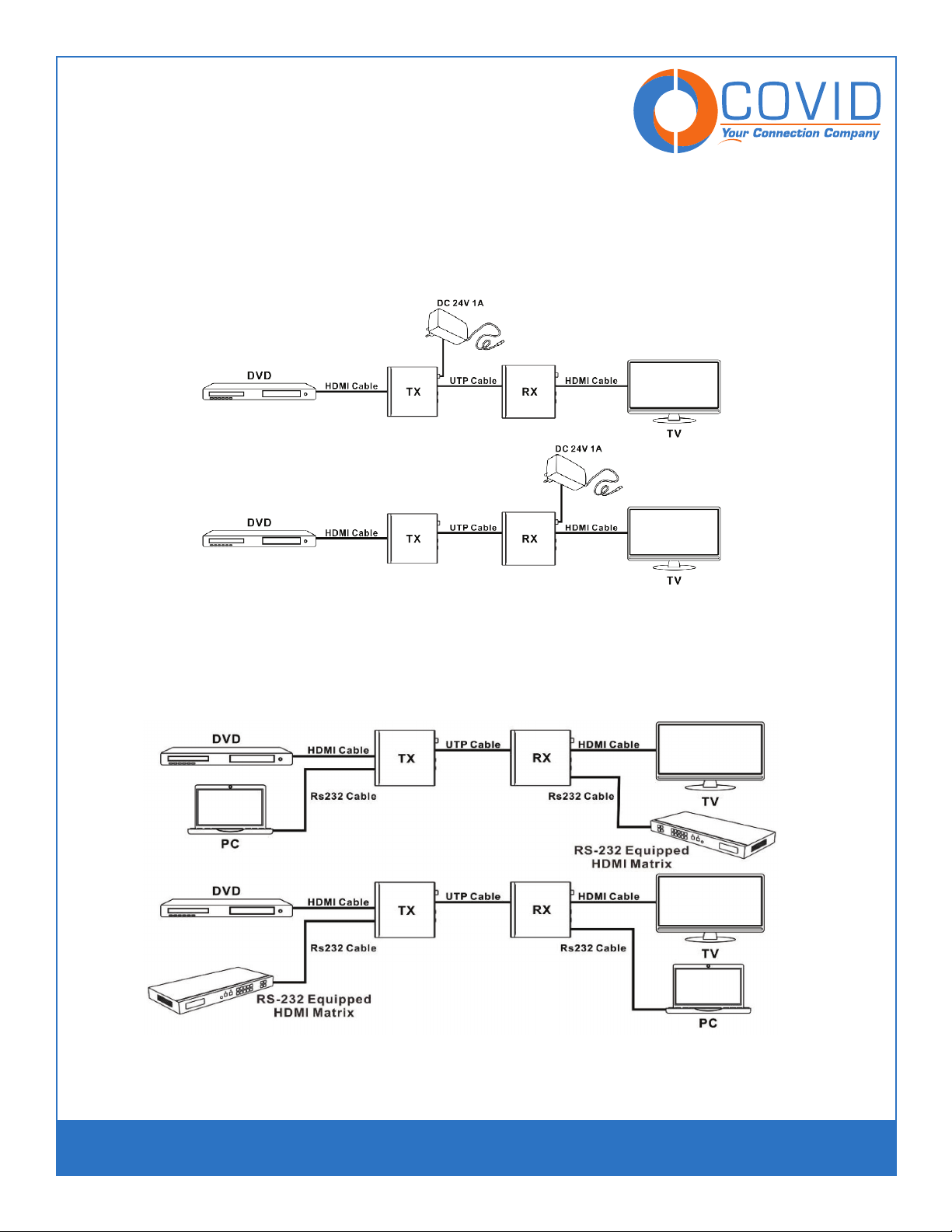
•POC (Power Over Cable) functionality is supported, either TX or RX is powered by a 24V@1A power
supply. POC Power consumption is less than 10W.
See application example 1 (pg. 6)
•Transfer Bidirectional RS-232 control signal together with the HDMI signal.
See application example 2 (pg. 6)
•Bidirectional RS232 Control Application Example
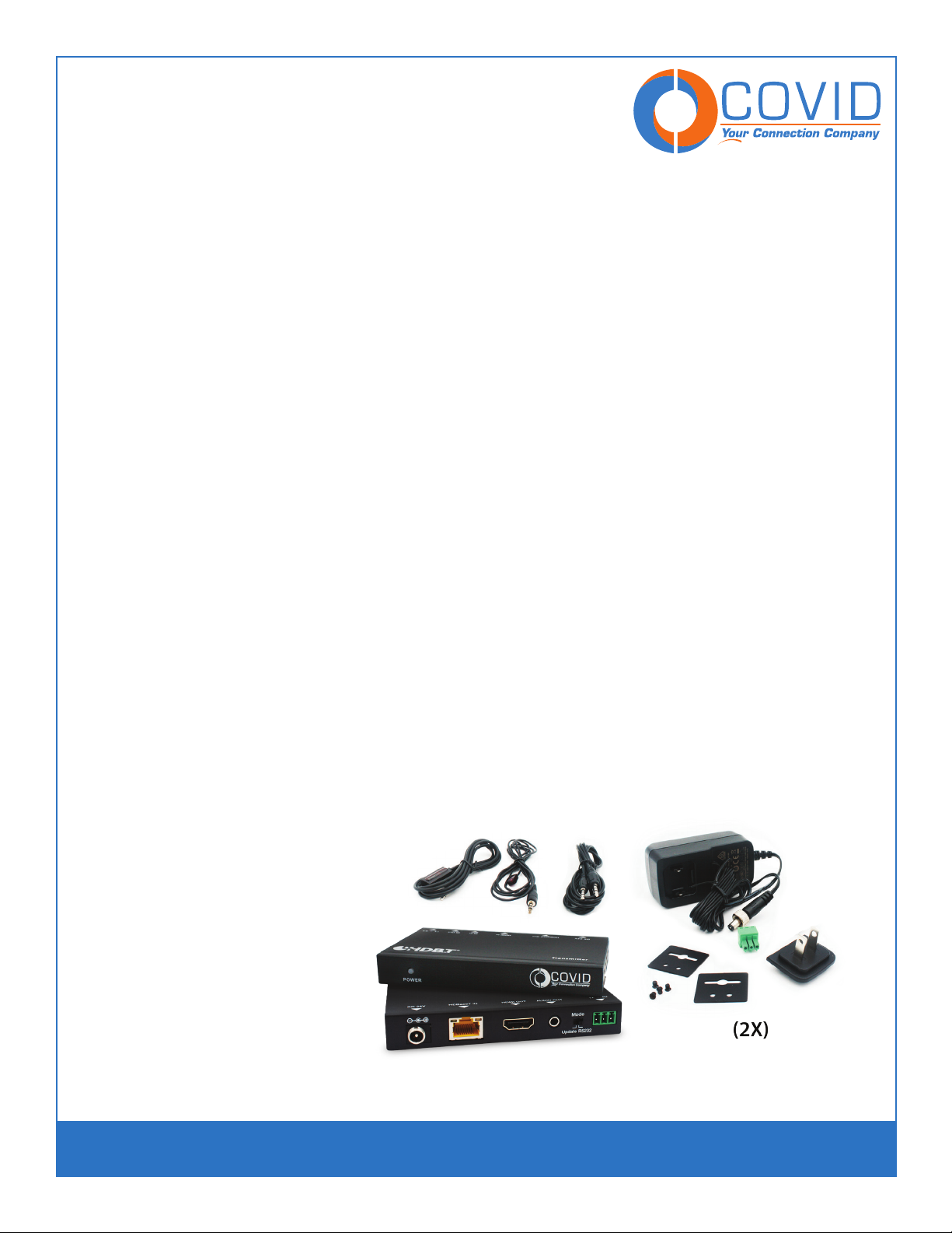
Package Contents
•HDMI Extender Transmitter - (1x)
•HDMI Extender Receiver - (1x)
• Wideband IR Emitter - (1x)
• Wideband IR Receiver - (1x)
•3.5mm Audio Cable - (1x)
•24V1A DC Power Supply - (2x)
•Mounting Brackets - (4x)
•3pin Screw Terminal Plug - (2x)
•Operation Manual - (2x)

EHB-120
USER MANUAL v1.0
1723 W. 4th Street Tempe Arizona 85281
P: 800.638.6104 | F: 480.966.6728 | E: sales@covid.com | www.covid.com Page 3
Technical
HDMI Compliance HDMI 1.4b
HDCP Compliance HDCP 2.2 and HDCP 1.4
Video Bandwidth 297MHz [10.2Gbps]
Video Resolutions up to,4K2K@30Hz,1080P@120Hz, and 1080P 3D@60Hz
Color Space RGB, YCbCr 4:4:4, YCbCr 4:2:2
Color Depth 10-bit, 12-bit
HDMI Audio Formats
(Pass-through)
LPCM 2/5.1/7.1CH, Dolby Digital, DTS 5.1, Dolby Digital+, Dolby TrueHD, DTS-HD Master Audio,
Dolby Atmos, DTS:X
ESD Protection Human body model - +/- 8kV (air-gap discharge) & +/-4kV (contact discharge)
Transmitter Connections
Inputs 1xDC Power In
1x HDMI Type A [19-pin female]
1x RS232 [Screw Terminal]
1x IR Receiver
Outputs 1x HDBaseT In [RJ45]
1x IR Emitter
Connections - Receiver
Inputs 1xDC Power In
1x HDBaseT In [RJ45]
1x RS232 [Screw Terminal]
Outputs 1x HDMI Type A [19-pin female]
1x Audio OUTPUT [3.5mm Stereo Mini-jack]
Mechanical
Housing Metal Enclosure
Color Black
Dimensions 65mm [W] x 115mm [D] x 17mm [H]
Weight 200g
Power Supply Input: AC100 - 240V 50/60Hz
Output: DC 24V/1A (US/EU standards, CE/FCC/UL certied)
Power Consumption 6W (Max)
Operation Temperature 32 - 104 °F / 0 - 40 °C
Storage Temperature -4 - 140°F / -20 - 60°C
Relative Humidity 20 - 90% RH (no condensation)
Technical Specifications

EHB-120
USER MANUAL v1.0
1723 W. 4th Street Tempe Arizona 85281
P: 800.638.6104 | F: 480.966.6728 | E: sales@covid.com | www.covid.com Page 4
Operation Controls and Functions
Transmitter
1. POWER: This LED illuminates when the device is connected with power supply.
2. DC 24V: Plug the 24V DC power supply into the unit.
3. HD BaseT OUT: Standard HD BaseT signal output port. Connect HD BaseT receiver with a category
cable
following the standard of direct interconnection method.
4. HDMI IN: HDMI input port. This slot is where you connect the HDMI source.
5. IR IN: Channel 2 IR Receiver. Connect with Wideband IR Rx.
6. IR OUT: Channel 1 IR Transmitter. Connect with Wideband IR Tx.
7. RS232: Phoenix jack provide Serial port control signal from receiver or to receiver.
8. Connection Signal Indicator Lamp
*Illuminate: The Transmitter and Receiver are in good connections status.
*Flashing: The Transmitter and Receiver are in poor connections status.
*Dark: The Transmitter and Receiver are not connected.
9. Data Signal Indicator Lamp
*Illuminate: The HDMI signal with HDCP.
*Flashing: The HDMI signal without HDCP.
*O: No HDMI signal.

EHB-120
USER MANUAL v1.0
1723 W. 4th Street Tempe Arizona 85281
P: 800.638.6104 | F: 480.966.6728 | E: sales@covid.com | www.covid.com Page 5
Operation Controls and Functions
5.1 Receiver Front and Rear Panel
1. Power LED: System power indicator.
2. DC 24V: Connect 24V/1A adapter to AC wall outlet for power supply.
3. HDBaseT In: HDBaseT signal input port. Connect HDBaseT transmitter with a category cable.
4. HDMI Out: HDMI output port.
5. Audio Out: Analog audio output from HDMI signal.
6. Mode: The Update Mode and the RS-232 mode selector.
•Update Mode: When the dial switch is set to update, port 7 is used to update or control the device.
•RS-232 Mode: When the dial switch is set to RS232, port 7 is used for RS232 pass-thru
communication.
7. RS-232: RS232 communication port that passes through from transmitter to receiver and receiver to
transmitter.
8. Connection Signal Indicator Lamp
•On (Solid): The Transmitter and Receiver are communicating.
•Flashing: The Transmitter and Receiver are not communicating properly.
•O: The Transmitter and Receiver are not connected by a category cable.
9. Data Signal Indicator Lamp
•On (Solid) The HDMI signal is carrying HDCP.
•Flashing: The HDMI signal is not carrying HDCP.
•O: No HDMI signal.

EHB-120
USER MANUAL v1.0
1723 W. 4th Street Tempe Arizona 85281
P: 800.638.6104 | F: 480.966.6728 | E: sales@covid.com | www.covid.com Page 6
Application Example 1
POC (Power Over Cable) Application Example
Application Example 2
Bidirectional RS232 Control Application Example

EHB-120
USER MANUAL v1.0
1723 W. 4th Street Tempe Arizona 85281
P: 800.638.6104 | F: 480.966.6728 | E: sales@covid.com | www.covid.com Page 7
Preparing RS232 Cable
What you will need:
• A two-conductor cable with ground terminated with DB9 connectors or not
• Wire strippers
• Screwdriver (at head)
• 3.5mm captive screw connector with 3 positions (included with plate)
• Heat gun and heat shrink (optional)
• Multimeter (optional)
Depending on your setup, you will need an RS232 cable with terminal block on one end to connect to the unit
and either another terminal block or DB9 on the other side. The focus of this section will be on terminating the ter-
minal block side with the proper pinout because that is what is connected to the unit. The other end of the cable
is dependent on what the unit is connecting too, but all the information in this section will help to get the proper
pinout in any case. As a tip, if connecting to a computer without a serial port, a USB to serial port converter can be
used to communicate with RS232.
If the cable is terminated on both sides, start by cutting o the end that will be used for connecting to the unit.
Then, strip the outer jacket of the cable back by about 1 inch like what is shown in Step 1 below. Once the outer
jacket is removed, you can optionally add heat shrink around the conductors and over the exposed drain wire like
in the picture of step 2. Next, strip the ends of the conductors back about 3/16” in order to make good contact in-
side of the captive screw connector. The nal step is to attach the captive screw connector to the end of the cable
matching the conductors on the other side of the cable to what is shown in step 3, use the connectors shown in
the following gure as a reference if using DB9 male or female. Test the conductors with a multimeter to conrm
termination.

EHB-120
USER MANUAL v1.0
1723 W. 4th Street Tempe Arizona 85281
P: 800.638.6104 | F: 480.966.6728 | E: sales@covid.com | www.covid.com Page 8
NOTE:
When using the device for pass-through, keep in mind that the side (either Tx or RX) that is connected to the device
that the commands are getting sent to will require that the Tx and Rx pins get swapped around (serial null modem
wiring). This means pin 2 of the DB9 connector will connect to the Rx pin of the HDBaseT device and pin 3 of the
DB9 connector will connect to the Tx pin of the HDBaseT device.

EHB-120
USER MANUAL v1.0
1723 W. 4th Street Tempe Arizona 85281
P: 800.638.6104 | F: 480.966.6728 | E: sales@covid.com | www.covid.com Page 9
Firmware Update Process
1. First power down the unit and remove all the cables from the IO port.
2. Connect the Rs232 port and slide the“Mode” switch to “Update” position
3. Open up COMSIP rmware update program
4. Follow the sequence below on the upgrade program
1Select the COM port,
2Select MCU as SSOP28
3Click the Connect tab.
4Click the Open tab to select the FW le for update.
5Click the Upgrade tab. The unit will begin sending 80 00 00 sequence in the TX:
1 2 3
4
5

EHB-120
USER MANUAL v1.0
1723 W. 4th Street Tempe Arizona 85281
P: 800.638.6104 | F: 480.966.6728 | E: sales@covid.com | www.covid.com Page 10
5. Once the 80 00 00 sequence begins, plug in the power to the Receiver and FW upgrade process
will begin.

EHB-120
USER MANUAL v1.0
1723 W. 4th Street Tempe Arizona 85281
P: 800.638.6104 | F: 480.966.6728 | E: sales@covid.com | www.covid.com Page 11
6. Wait till the program is veried and then click the Disconnect tab. Once this is done, power o and
restart the unit before use.
7. To verify the rmware version, please open up the serial terminal. Make sure the Mode switch is at
Update position.
Default baud rate 9600, data bits = 8, stop bits = 1, parity = none
Command Feedback
?fw<cr> (FW x.xx)
Once this is conrmed, please remember to move the Mode switch to Rs232 for the unit pass though
Rs232 feature.

EHB-120
USER MANUAL v1.0
1723 W. 4th Street Tempe Arizona 85281
P: 800.638.6104 | F: 480.966.6728 | E: sales@covid.com | www.covid.com Page 12
RS232 Commands
Action Basic ASCII String Variables
Setting the EDID mode >edid:a<cr> a = EDID mode
(ext = external
int = internal)
Query EDID mode ?edid<cr>
Query rmware ?fw<cr>
> - Command, ? - Query
<cr> = 0x0D Hex / 13 Decimal
Note: The default communication settings are 9600 8N1 None.

EHB-120
USER MANUAL v1.0
1723 W. 4th Street Tempe Arizona 85281
P: 800.638.6104 | F: 480.966.6728 | E: sales@covid.com | www.covid.com Page 13
RS 232 Application Example

EHB-120
USER MANUAL v1.0
1723 W. 4th Street Tempe Arizona 85281
P: 800.638.6104 | F: 480.966.6728 | E: sales@covid.com | www.covid.com Page 14
To reduce the risk of electric shock, do not expose this product to rain or moisture.
Do not modify the wall plug. Doing so will void the warranty and safety features.
If the wall plug does not t into your local power socket, hire an electrician to replace your
obsolete socket.
This equipment should be installed near the socket outlet and the device should be easily
accessible in the case it requires disconnection.
Safety Information
!
!
!
!
Warranty
Parts and labor warranty time is three year and from the date of original shipment. This warranty shall be
void if a serial number has been removed from the product.
Upon determination of a legitimate defect covered by this warranty and at COVID’s sole discretion, user
should bear the transport cost during the warranty.
If product is out of warranty then repair charge is required. Out of warranty repairs will only be made
after cost has been approved by Customers and proper nancial arrangements are made. Customer must
cover round trip shipment expenses.
Table of contents
Other Covid Transmitter manuals
Popular Transmitter manuals by other brands

Radio Systems
Radio Systems TR-6000 operating instructions

OTS
OTS HD-SDI Series Quick installation guide

Acromag
Acromag IntelliPack 895M Series user manual

Comet
Comet Continental 419F Replacement guide

Inovonics
Inovonics EchoStream EN1242 installation instructions

Siemens
Siemens SITRANS TH400 operating instructions