CPI TALOS Operation manual

TALOS
OPERATION AND SERVICE GUIDE

Talos Operation and Service Guide
2

Talos Operation and Service Guide
3
General Information
Overview
This Operation and Service Guide contains important information on installing, operating,
and maintaining a CPI, Inc. Talos Bill Acceptor. To obtain the best performance from your
CPI, Inc. Bill Acceptor, read this manual and the Installation Guide before installing and using
the bill acceptor.
Restrictions
For a list of compatible vending machines, consult your CPI sales representative, CPI
authorized distributer, or CPI’s web site, cranepi.com/support.
Product Summary
Acceptance Rate
•95% or greater for $1, $5, $10, $20, $50 and $100, at nominal conditions.
Bill insertion
•Lengthwise, four way (Face up/down, either direction).
Transaction Speed
•Approximately four seconds – from bill insertion to completed bill-stacking.
Interface
•See the Interface section on Page 18 for details
Power Sources
•90 to 135 VAC, 60Hz or 18 to 28 VAC, 60Hz, 22VDC to 45VDC or 12VDC
Power Consumption
•Standby: 5 Watts
•Acceptance: 10 Watts
•Full Stack Max: 50 Watts
Escrow
•One Bill
Shipping Weight
•Four pounds

Talos Operation and Service Guide
4
Environment
•Operating temperature: -15°C to 60°C
•Storage temperature: -40°C to 70°C
•Humidity: 5% to 95% relative humidity (non-condensing), maximum relative humidity
of 50% at extreme temperatures.
Bezel Styles
The Talos offers three new bezels:
•The Compact Bezel allows for ease of bill insertion with lighted arrows pointing to the
place of insertion.
•The VFM Retrofit Bezel is modelled after the familiar bezel from the VFM Series Bill
Acceptor. Dimensions are the same as the standard VFM Series bezel.
•The High Visibility Bezel catches the customer’s attention with a wide range of LEDs
and clearly indicates which denominations the vendor accepts.
It will also work with the legacy VN bezel sets, including:
•The Compact Bezel
•The VFM Retrofit Bezel
•High Visibility Bezel
•The Flush Mount Bezel
Bezel Conversion Kits
Bezel Conversion Kits are available to convert one bezel to another style.
Name
Compact Bezel
VFM Retrofit Bezel
Part Number
250011005P
250028086P
Image

Talos Operation and Service Guide
5
Magazine Styles
The Talos is compatible with the following CPI bill magazines:
Capacity
Access
Part Number
200
Top door removal
250063015
300
Top door removal
250061016
500
Hinged Side-Door Removal
253115019
700
Hinged Side Door Removal
250068021
1000
Hinged Side Door Removal
250060086
If necessary, you can easily replace any magazine with another method of bill removal.
Cables
Cable
Part Number
Image
110VAC Power Cable 250077006
24VAC Power Cable 250075007
MDB Cable 250071043
USB EBDS Cable 250079066P1
Standard EBDS Cable 250079049P
12V Battery Cable 250072110P

Talos Operation and Service Guide
6
Specifications
Power ratings for the units are:
•110VAC / 60 cycles at 0.5 amps
•24VAC / 60 cycles at 2.0 amps
•34 VDC at 2.0 amps (MDB mode)
UL Listing
The Talos is listed under UL File #
Warranty
All Talos bill acceptors come with a Two Year Manufacturer's Warranty. After inspecting the
unit, record the model and serial numbers from the label on the side of the bill acceptor.
Refer to these numbers when you call CPI for service. The manufacturer's warranty is based
upon the date of manufacture.
Parts and labor are included for In-Warranty repairs.
The first three digits of the serial number contain the manufacturing date code. This code
indicates the beginning of the warranty period. The first two digits indicate the week of
manufacture; the third digit indicates the year of manufacture. For example: a bill acceptor
with a serial number of 30720033333 was manufactured in the 30th week of 2017 (July
2017).

Talos Operation and Service Guide
7
INSTALLATION
Please note that a single page installation guide for the Talos can also be found on our
website.
Unpacking the Bill Acceptor
Unpack the bill acceptor and immediately inspect it for damage. If the unit is damaged,
return it to its original carton along with packing materials.
Notify the delivering carrier of damages and request immediate inspection. Send a letter of
intent to file a claim to the delivering carrier within 72 hours from the time of delivery. Send a
copy of the letter to the shipper.
Only the person or company receiving the bill acceptor can file a claim against the carrier for
concealed damages. Keep the original packing materials for shipping or transporting the bill
acceptor.
Mounting
The Talos mounts easily onto existing studs provided by Original Equipment Manufacturers
(OEMs).
Some vending machines require brackets or faceplates to mount the unit properly. Refer to
the vending machine’s operation manual or contact your distributor/OEM for more model-
specific mounting information.
1. Turn off power to the vending machine.
2. Mount the Talos bill validator on the mounting studs, through the opening in the front
of the vendor and secure using the included hardware.
3. Connect the Talos bill validator to the MDB harness. Apply gentle pressure to
connect; the pins will bend if forced.
4. Turn on power to the vending machine.
5. Check the LEDs on the front of Talos. The LEDs should be flashing. In some cases,
the machine door must be closed first.
6. Once the LEDs are flashing, test the validator with a $1 bill.
a. Insert $1 and confirm that it stacks and credit is given.
b. Repeat this process for any other enabled bills.
7. When your test is complete, remove the test bills from the bill magazine.

Talos Operation and Service Guide
8
OPERATION
Functional Overview
The Talos performs on the following processes to accept, validate and process a bill:
Process
Details
Bill detection
Talos senses the bill and prepares the drive motor.
Bill transport
Drive belts pull the bill into the machine.
Bill recognition
Internal sensors scan the bill to determine value.
Bill validation
The bill is held in escrow as it is validated as a real bill.
Credit or return
Credit is applied if the bill is valid or the bill is returned to the
customer if not.
Bill Storage
The bill is stacked into the cassette or recycler.
Enabling Bills and Vend Coupons
Follow this process to enable or disable bills or vend coupons:
1. Remove the bill magazine, then use a pencil or a screwdriver to press the button to
enter configuration mode:
2. Reattach the bill magazine.
3. Insert the bill or vend coupon.
4. The bezel LEDs flash when the bill or vend coupon is returned.
5. Count the flashes to determine the outcome using the chart on the next section.

Talos Operation and Service Guide
9
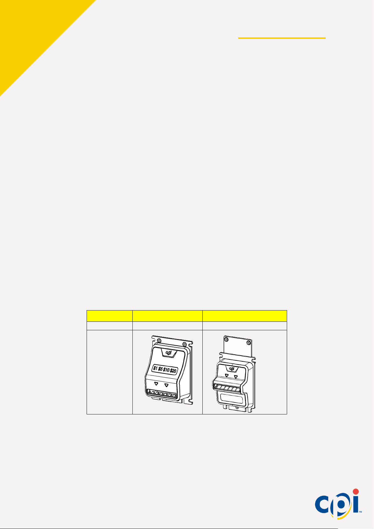
Coupon Configuration
The Talos can be configured using a configuration coupon. This coupon is included in the
Installation Guide. Copies of the original coupon may be produced with a standard, carbon-
based, non-color copier. Cut copies to match the size of the original coupon.
The coupon selection will be stored in the unit until it is reprogrammed, even if power is
removed.
When filling out the coupon, note the following:
•Use only a #2 pencil to fill in the blocks
•Fill in the entire block
•Do not mark the coupon outside the blocks or on the back of the coupon
•Fill ONE block for every line.
The unit is pre-configured with the following options enabled:
•Accept $1 bills
•Four way accept
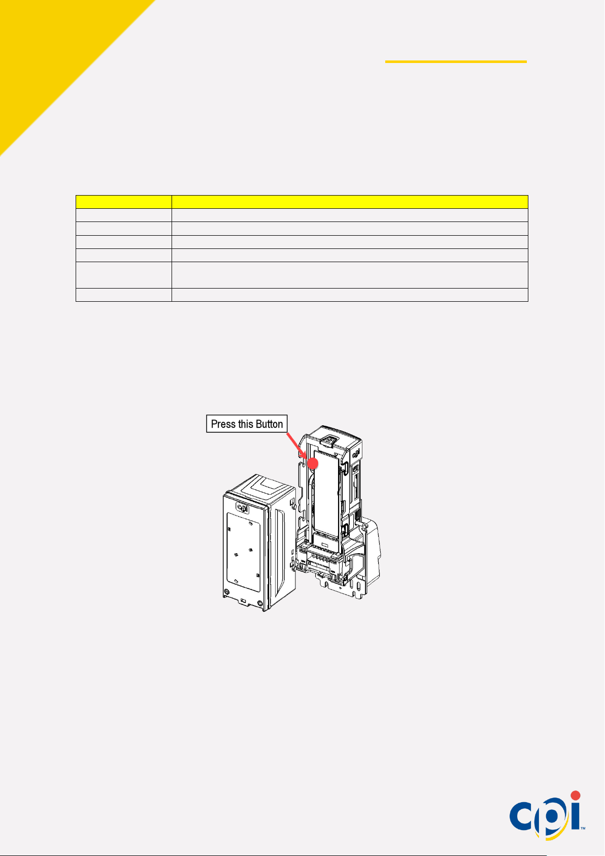
Use the included coupon to change the settings:
1. Carefully cut out the coupon
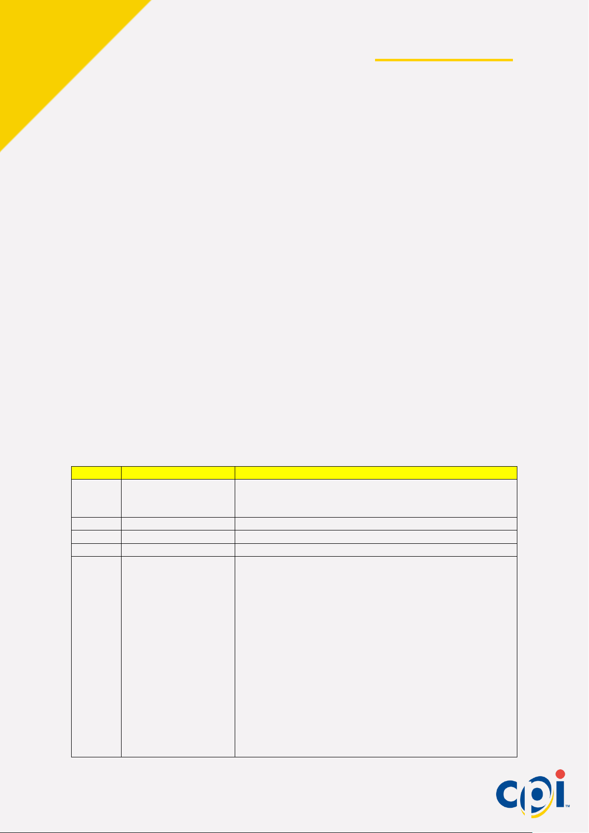
2. Fill out each line using an HB or #2 pencil
Section
Changes
Options
1
Bill Way Accepted
1 – Face up in one direction (Green Seal First)
2 – Face up in either direction
4 – Face up or down in either direction
2
Bills Enabled
On or off to enable or disable a bill
3
Recycled Bill
Can be left blank, but is required for the recycler
4
Accept Inhibit
Requires a recycler
5
Acceptance Mode
Mode 0: Factory default. No acceptance modes active.
Mode 1*: If fraud is detected the validator enters an out-
of-service time-out, the stacker plate extends into the bill
magazine and the bezel LEDs flash. If any sensors are
blocked, the time-out persists until the blockage is
cleared.
Mode 2*: All the features of Mode 1, plus the stacker
plate extends into the bill magazine when idle.
Mode 3*: All the features of Mode 2, but more
aggressive. It may increase jams and service calls.
Mode 3 is recommended for temporary use only.
*Requires power

Talos Operation and Service Guide
10
3. Insert the configuration coupon and verify the settings were accepted by counting the bezel
flashes:
Flashes
Meaning
10
Configuration coupon accepted and unit successfully programmed
1 – 5
Coupon rejected. The number (1 – 5) of flashes corresponds to the coupon
section that was improperly filled out.
7
Coupon not read. Confirm the coupon is correct and try again.

Talos Operation and Service Guide
11
CPI SYNQ
The Talos was designed in tandem with the CPI Synq. CPI Synq is a connected platform
that enables simplified full-system diagnostics and remote management of CPI payment
devices on any machine, all in the palm of your hand.
CPI Synq redefines your cash experience:
•Simple, visual diagnostics
•Video instruction and guided troubleshooting
•Configuration controls
•Optimal cash float in the machine
•Remote system monitoring
•Improved up-time in the field
•Lower total cost of ownership across all CPI Synq connected devices
Features
Feature
Description
MDB Sniffing
Get at-machine or remote diagnostics, enabling fast and
accurate troubleshooting which reduces cost of ownership.
PayRange mobile
payment compatible
Increase sales by enabling remote payment options.
Performance
analytics
Monitor your route with the Simplifi DMS
Over-the-Air software
and currency
updates
Remote software changes lower cost of ownership by cutting
down on time spent at the machine
Asset Management
Change device configurations easily via the app

Talos Operation and Service Guide
12
Installation
Create an Account
Visit cranesimplifi.com/register/Synq to create an account. This only needs to be done at
the operator level, and only needs to be done one time.
Download the Simplifi app
Search the iPhone App Store for “Simplifi”and download it to your mobile device.
Assign the Synq
Each Synq must be registered via the Simplifi app, which requires internet access to
complete the registration process.
1. Connect the Synq via MDB to a power source and open the Simplifi App (See
Installation for Synq power connection details).
2. On the POS list, locate the device labeled “Unknown POS”
3. Press the + icon next to “Unknown POS” and name the Synq to help identify it later.
For example, “Second Floor Snack Machine”.
4. Once you’ve named the Synq, the registration process is complete. It is ready to be
installed into a vendor. See Installation for details.
The Synq will now appear in your list of devices when you are within Synq’s 100ft broadcast
range.
If you ever need to unregister a device, press and hold the button on the side of the Synq to
activate Discovery Mode. Discovery Mode allows you to re-assign the Synq. If you do not re-
assign, the Synq reverts to current state.
Connect the Synq to Talos
CPI Synq can be installed in series, anywhere on the MDB line that makes it easy for you to
operate. Both ends of the MDB must be connected and the four pin connector should be
inserted into the CPI Synq port on the Talos:

Talos Operation and Service Guide
13
Synq Simplifi App
Our simple app features troubleshooting and video tutorials for common vending errors, in
addition to providing easy-to-use configuration and diagnostic tools.
Troubleshooting with the Synq App
When in range of Synq enabled vendors, our beacon technology allows you to quickly
review the health of your machines. The clean design and at-a-glance icons greatly reduce
the time spent on service calls.
Each vendor is listed with its serial number and a colored icon indicating its general health.
Green is healthy, yellow is needs attention and red is out of service.
Tapping any vendor on the list gives access to all alarms from all its peripherals, allowing the
technician to quickly identify problems. Each alarm is listed in priority order, with simple one-
line descriptions of each alarm:

Talos Operation and Service Guide
14
Tapping any error gives the user access to a troubleshooting guide. One more tap provides
more detailed troubleshooting steps and/or instructional videos to encourage single-visit
solutions:

Talos Operation and Service Guide
15
Configuring Talos with the Synq App
You can make basic configuration changes to the Talos when using the Synq app. Connect
to the Talos you’d like to configure and then select your preferences and tap update to save
your changes.
Synq Error Codes
The Status LED on the side of the Synq provides at-a-glance information about the Snyq’s health.
Color
Sequence
Meaning
Green
Steady On
Synq is working properly
Red and
Green
Alternating
Boot up sequence
Green
Fast
Flashing
Active connection to Simplifi
App
Green
Slow
Flashing
Updating
Firmware/Configuration
Amber
Steady On
Synq is not assigned
Amber
Fast
Flashing
Discovery Mode
Red
Unit
failure,
replace
Unit failure, replace

Talos Operation and Service Guide
16
INTERFACES
•
The “interface” refers to the transfer of electronic data to and from the bill acceptor and the
controlling device. The controlling device in a vending machine is either the machine
controller or the coin mechanism. The signals transferred to the bill acceptor are control
signals which may include:
•The control system is ready to accept money
•The denomination of bill to accept
•Whether or not bills should be returned from escrow
The Talos is capable of operating with the following interfaces:
Vending Interfaces
Interface
Description
ILLP
Isolated Low Level Pulse
NILLP
Non-Isolated Low Level Pulse
MDB
Multi-Drop Bus
NISR
Non-Isolated Serial
Gaming Interfaces
Interface
Description
NISR
Non-Isolated Serial
IP
Isolated Pulse
NIP
Non-Isolated Pulse
EBDS
Extended Bi-Directional
NIP+
Non-Isolated Pulse+
Features
Features included in the interfaces are Escrow, Lockout, Credit Pulse and Out of Service
Line Indication.
Escrow
The bill can be held indefinitely and then can either be accepted or returned prior to being
stacked. Escrow allows a vending machine control system to decide whether or not the last
valid bill inserted will be credited or returned to the user.
Normally, a valid bill will be accepted and held in mid-transport. At this point, the bill acceptor
will transmit the value of the bill. The control system then decides to keep or return the bill.
If the bill was kept, the bill acceptor completes transportation of the bill and transmits
confirmation that the bill was stacked.
Accept Enable (Lockout)
The accept enable feature allows the control system the option of disabling the Bill Acceptor.
This function is controlled by the "Accept Enable" interface lines.

Talos Operation and Service Guide
17
Out of Service Line Indication
The Talos Bill Acceptor provides, as part of the interface connector, an out of service
indicator signal. The out of service signal will be active when the bill acceptor is not enabled
to accept bills for any reason. Such conditions include: full bill magazine, missing bill
magazine, all denominations disabled, jams, and internal malfunctions. The output, when
active, sources 10ma at 5 Volts DC.
An out-of-service output signal is available under all interfaces. The NISR, MDB, and EBDS
interfaces also provide serial messages to indicate various out-of-service conditions.
Isolated Low Level Pulse (ILLP) Interface
The ILLP interface is an isolated interface that sends credit information in the form of pulses
via the Credit Relay. From one to four pulses (model dependent) per unit of credit is
selectable along with two different pulse patterns (model dependent). Optically isolated sink
or source inputs provide external acceptance enable control for three different bill types.
Escrow return of the last bill is also supported via an optically isolated sink or source
ESCROW input.
Connections
Pin Name (all pins refer to P1)
Type
115 VAC
pin
24 VAC
pin
12VDC pin
115VAC HOT / 24VAC HOT/ 12VDC HOT
Power
20
3
19
115VAC NEUTRAL / 24VAC NEUTRAL/
12VDC Return Power 4 2 16
Earth
Power
21
None
None
Denom 1 ENABLE, High
Input
15
15
15
Denom 2 ENABLE, High
Input
14
14
14
Denom 3 ENABLE, High
Input
13
13
13
ESCROW, High
Input
12
12
12
Denom 1 ENABLE, Low
Input
27
27
27
Denom 2 ENABLE, Low
Input
28
28
28
Denom 3 ENABLE, Low
Input
29
29
29
ESCROW, Low
Input
30
30
30

Talos Operation and Service Guide
18
CREDIT RELAY, Normally Open
Output
16
2
2
CREDIT RELAY, Common
Output
1
1
1
OUT-OF-SERVICE POWER (200 ohms to
+5VDC) Output 25 25 25
OUT-OF-SERVICE_NOT
Output
22
22
22
Input Signals
The Talos Bill Acceptor is controlled by the Control System via the following four pairs of
input signals.
Denomination
1 ENABLE, denomination 2 ENABLE, and denomination 3 ENABLE (High or Low) are three
independent, optically isolated input pairs allowing either sink or source enable control for
three different bill types. These input pairs are activated by the application of 5VDC1 to
ENABLE (High) and GROUND1 to ENABLE (Low). Note that either the High or Low input
can be connected directly to its appropriate level while the other input becomes the switched
input for controlling the enable function.
Deactivation of any of the signals prevents the appropriate bill from being accepted;
however, the control board must provide for a one second timing window after deactivation
to allow a bill already in process to be accepted.
Denomination 1 ENABLE, denomination 2 ENABLE, and denomination 3 ENABLE are also
used to allow user escrow. The appropriate ENABLE signal
must be disabled according to the timing diagram following acceptance of a bill to keep that
bill in the escrow position pending further instruction of the ESCROW signal. Reactivation of
the ENABLE signal without deactivation of the ESCROW signal will credit the bill.
Escrow
(High or Low) is an optically isolated input pair allowing either sink or source escrow control.
This input pair is activated by the application of 5VDC2 to ESCROW (High) and GROUND1
to ESCROW (Low). Note that either the High or Low input can be connected directly to its
appropriate level while the other input becomes the switched input for controlling the escrow
function.
Not activating the ESCROW signal will prevent a bill from being held in the escrow position.
1Both 5VDC and GROUND are referenced to the Control System, not the Bill Acceptor.
2Both 5VDC and GROUND are referenced to the Control System, not the Bill Acceptor.

Talos Operation and Service Guide
19
In essence, once the credit pulses for a bill have been sent, the bill will automatically be
accepted.
Activating the ESCROW signal and disabling the appropriate bill ENABLE signal after the
credit pulses for the bill have been sent will hold the bill in the escrow position. Keeping the
ESCROW signal active and re-enabling the processed bill ENABLE signal will accept the bill.
Disabling the ESCROW signal before enabling the processed bill ENABLE signal will return
the bill.
Note: For Talos Bill Acceptors which allow acceptance of higher denomination bills, Denom
1 ENABLE, Denom 2 ENABLE, and Denom 3 ENABLE all must be enabled to activate
acceptance of the higher denominations.

Talos Operation and Service Guide
20
Non-Isolated Low Level Pulse (NILLP) Interface
The NILLP interface is a non-isolated interface that sends credit information in the form of
pulses via a single, independent TTL compatible, open collector driver. From on e to four
pulses per unit of credit is selectable along with two different timing durations (patterns) of
the pulses. Optically isolated sink or source inputs provide external acceptance enable
control for three different bill types. Escrow return of the last bill is also supported via an
optically isolated sink or source ESCROW input.
Pin Name (all pins refer to P1)
Type
115 VAC
pin
24 VAC
pin
12 VDC
pin
115VAC HOT / 24VAC HOT/ 12VDC HOT
Power
20
3
19
115VAC NEUTRAL / 24VAC NEUTRAL/
12VDC Return Power 4 20 16
Earth
Power
21
None
None
Denom 1 ENABLE, High
Input
15
15
15
Denom 2 ENABLE, High
Input
14
14
14
Denom 3 ENABLE, High
Input
13
13
13
ESCROW, High
Input
12
12
12
Denom 1 ENABLE, Low
Input
27
27
27
Denom 2 ENABLE, Low
Input
28
28
28
Denom 3 ENABLE, Low
Input
29
29
29
ESCROW, Low
Input
30
30
30
CREDIT-PULSE_NOT
Output
7
7
7
LOW LEVEL GROUND
Ground
10
10
10
OUT-OF-SERVICE POWER (200 ohms to
+5VDC) Output 25 25 25
OUT-OF-SERVICE_NOT
Output
22
22
22
Table of contents
Other CPI Bank Note Validator manuals