Craftsman 48092 User manual

Operator’s Manual
Model 48092
WARNING: Before using this product,
read this Operator’s Manual and follow
all its Safety Rules and Operating
Instructions.
Sears Brands Management Corporation, Homan Estates, IL 60179 U.S.A.
www.craftsman.com
• Safety
• Operation
• Maintenance
Printed in China
3 Ton Service Jack
ASME PASE Compliant
CUSTOMER HELP LINE
Parts and Questions
1-888-332-6419
8:00 AM - 4:45 PM Central Time
Monday- Friday

2
NOTE: Repeat this
Air Purge Procedure
whenever the jack
displays reduced
lifting performance.
CUSTOMER HELP LINE
Parts and Questions
1-888-332-6419
8:00 AM - 4:45 PM Central Time
Monday- Friday
AIR PURGE PROCEDURE
IMPORTANT: BEFORE FIRST USE, perform the following Air Purge Procedure to remove any air that may
have been introduced into the hydraulic system as a result of product shipment and handling.
.
Pump Plunger
Insert Handle
See “ ASSEMBLY” on page 4 to
assemble handle. Loosen handle
socket screw. Insert end of handle
into handle socket. Tighten screw.
Rapidly Pump
Rapidly pump the handle 6 - 8
times. Leave handle in down
position to expose oil ll screw.
Turn Handle
Counterclockwise
Turn handle counterclockwise
two full turns to fully open
release valve.
Screwdriver
Oil Fill Screw
Turn Handle Clockwise
Turn the handle clockwise until it
stops.
6READY TO USE
Jack is now ready for use. Check
for proper pump action.
Purge Air
With a at blade screwdriver,
loosen the oil ll screw
about halfway up to release
trapped air from
the system. Tighten the
screw back down.

3
This jack features a 6,000 lbs. maximum load
capacity. Lifting range for this jack is 5-3/8
inches to 19-1/2 inches. Jack features an
overload valve bypass system to prevent jack
damage and user injury.
Specications
Compact design allows use in conned spaces
Maximum load capacity........3 tons (6,000 lbs.)
Service jack lift range.....5-3/8 to 19-1/2 inches
Weight....................................................75 lbs.
WARNING: This product contains chemicals
known to the state of California to cause
cancer and birth defects or other reproductive
harm. www.P65Warnings.ca.gov
SAFETY INSTRUCTIONS CRAFTSMAN LIMITED WARRANTY
DESCRIPTION
Read Operating Instructions
Study, understand and follow all instructions in
this manual before operating the jack. Failure
to heed these warnings may result in loss of
load, damage to the jack and/or jack failure
resulting in personal injury or property damage.
Position the Jack
This jack is designed only for lifting part of
the total vehicle. Position the jack to only lift
on the areas of the vehicle specied by the
vehicle manufacturer.
Use Support Stands
After lifting the vehicle always support the
load with appropriately rated vehicle support
stands before working on the vehicle.
Do Not Overload Jack
Do not overload this jack beyond its rated
capacity. Overloading this jack beyond its
rated capacity can cause damage to or failure
of the jack.
Use on Hard Level Surface
This jack is designed only for use on hard level
surfaces capable of sustaining the load. Use
on other than hard level surfaces can result in
jack instability and possible loss of load.
Center Load on Jack Saddle
Center load on jack saddle before lifting
vehicle. O-center loads and loads lifted
when the jack is not level can cause loss
of load or damage to the jack. Only use on
vehicles whose lift points t well with saddle
of this jack.
Do Not Use Jack as Dolly
Do not move or dolly the vehicle while it is on
the jack. Do not use this jack to lift or move
a building, mobile home or travel trailer of
any type.
KEEP HANDS AND FEET CLEAR OF
THE JACK HINGE MECHANISM AND
GROUND CONTACT AREA WHEN
LOWERING THE LOAD!
CRAFTSMAN LIMITED WARRANTY
FOR ONE YEAR from the date of sale this
product is warranty against defects in material
or workmanship. WITH PROOF OF SALE
a defective product will be replaced free of
charge.
For warranty coverage details to obtain
free replacement, visit the web page: www.
craftsman.com/warranty
This warranty applies for only 90 days from
the date of sale if this product is ever used
while providing commercial services or if
rented to another person.
This warranty gives you specic legal rights,
and you may also have other rights which vary
from state to state.
Sears Brands Management Corporation,
Homan Estates, IL 60179
THIS IS A LIFTING DEVICE ONLY!
DO NOT work on vehicle supported by jack.
Immediately after lifting, support load with
appropriately rated vehicle support stands before
working on vehicle.
4
ASSEMBLY
FEATURES & OPERATION
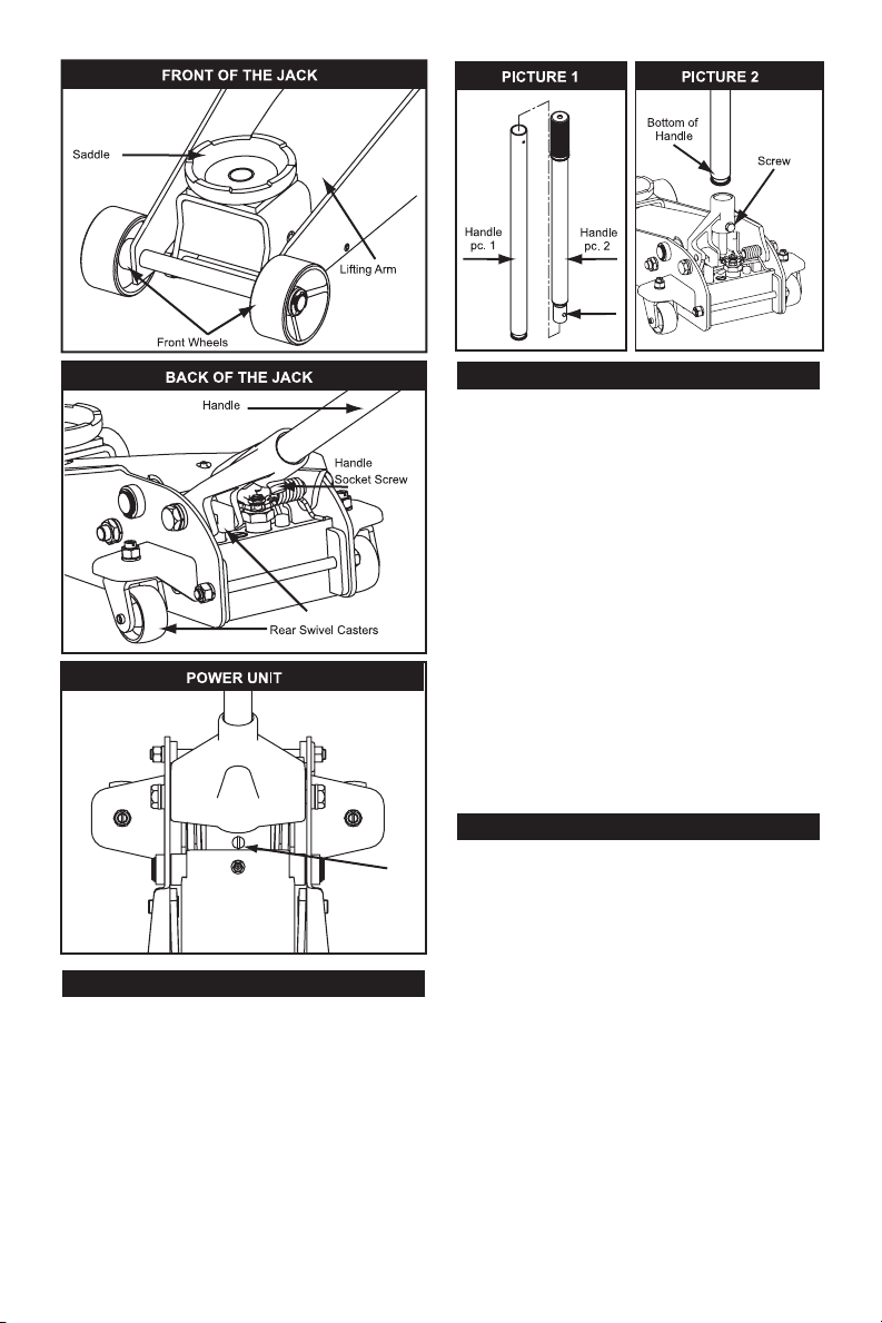
Assembly
Handle Assembly
• Refer to Picture 1 when performing this step.
Align Quick Disconnect pushpin in upper
handle piece with attachment hole in lower
handle piece. Push upper piece into lower
piece until pushpin pops through hole.
• Suciently loosen the Handle Socket Screw
to insert the assembled handle (Picture 2).
• Line up the square shaped hole located at
the bottom of the handle over the square
bolt inside the Handle Socket.
• Lower the handle onto the bolt. Secure the
handle in place by tightening the Handle
Socket Screw until the handle stops rotating.
NOTICE: ONLY use the handle provided
with this jack. Handle is specially designed
to properly t into handle socket and engage
release valve.
Operation
Raising the Jack
• Place vehicle in park, with emergency brake
on and wheels securely chocked to ensure
lifting stability.
• Refer to the vehicle manufacturer owner’s
manual to locate the approved vehicle lifting
points.
• Position the jack so that the saddle will rmly
contact the vehicle lifting point.
• Close the release valve by turning the
handle clockwise until it stops.
• Pump jack handle until saddle nears contact
with vehicle lifting point. Check to see that
the saddle is centered and will contact lifting
point rmly.
Oil Fill
Screw
Pin
Pump Plunger
PREPARATION
Preparation
After rst removing from shipping box
• Carefully remove the retaining clip from the
back of the service jack.
CAUTION: The socket will tend to spring
upward when the clip is removed. To prevent
possible injury, place one hand on top of
socket to control its upward motion when
removing clip with other hand.

55
Maintenance
To Add Oil:
• Position jack on the level ground and lower
the saddle.
• Remove the oil ll screw.
• Fill the oil reservoir until oil level is just over
the top surface of the inner cylinder. Replace
oil plug.
• Perform Air Purge Procedure described on
page 2.
To Replace Oil:
• Fully open release valve by turning handle
counterclockwise as far as it will go.
• Remove the oil ll screw. Turn the jack over
so that old oil will drain from the oil ll hole.
• Turn the jack back over after the oil has
drained. Rell through oil ll hole. Keep dirt
and other material clear when pouring. Fill to
just beneath lower rim of hole. Replace oil ll
screw.
• Perform Air Purge Procedure described on
page 2.
Lubrication
• Add lubricating oil (WD-40) to all moving parts
when needed.
• For light duty use, lubricate every six months.
• For heavy and constant use, lubrication is
recommended every month.
MAINTENANCE
Rust Prevention:
• Check ram and pump plunger on the Power
Unit Assembly every two months (or sooner,
based on usage) for any signs of rust or
corrosion. Lift the jack as high as it goes
and look under and behind the lifting arm. If
signs of rust are visible clean as needed and
wipe down with with an oily cloth or cloth
sprayed with WD-40.
• When storing the jack, always have the
saddle and pump plunger in the down
postion.
ALWAYS USE A GOOD GRADE
HYDRAULIC JACK OIL. DO NOT USE
HYDRAULIC BRAKE FLUID, ALCOHOL,
GLYCERINE, DETERGENT, MOTOR
OIL OR DIRTY OIL. USE OF AN UN-
RECOMMENDED FLUID CAN CAUSE
DAMAGE TO YOUR JACK.
Air Purge Procedure
During shipment, air may get into the
hydraulic system causing reduced lifting
performance. Perform Air Purge Procedure
described on page 2.
• Continue to pump jack handle to lift vehicle to
desired height.
• After lifting, support the load with
appropriately rated vehicle support stands
before working on vehicle.
WARNING: Never work on, under, or around a
load supported only by a hydraulic jack.
Lowering the Jack
• Raise load high enough to clear jack stands;
then carefully remove the stands.
• Carefully open the release valve by slowly
turning the handle counterclockwise.
• After removing jack from under vehicle, if
saddle has not fully descended, push it all the
way down. This will reduce ram exposure to
rust and contamination.

6
Oil Fill
Screw
EXPLODED VIEW AND PARTS LIST
#Description Qty.
1 Saddle 1
2Lift Arm 1
3Side Plate Assembly 1
4 Front Wheel 2
5Rear Caster Assembly 2
6 Handle 1
7 Handle Socket 1
8Power Unit Assembly 1
TROUBLESHOOTING
Symptom
Jack will
not lift
load
Jack will
not hold
load
Jack will
not lift to
full height
Jack will
not lower
completely
Poor jack
lifting,
pump
feels
spongy
Handle
raises by
itself while
under load
X X X X Oil level is low in jack. Add oil
as required.
Probable Cause and Solution
X X X X X Power unit may have trapped
air. Release air from system.
X X X Release valve may not be
closing properly. Turn the
release valve clockwise tightly.
XOil reservoir is over-lled.
Drain out some oil.
XLubrication of moving parts is
necessary.
X X X Power unit is malfunctioning.
Replace the power unit.

7
7
NOTE

For Help Line, Parts and Service:
Call 8:00 am - 4:45 pm, CT, Monday - Friday
1-888-332-6419
Para la linea de ayuda, partes y servicio:
Llame de 8:00 am - 4:45 pm, CT, Lunes-Viernes
1-888-332-6419
Table of contents
Other Craftsman Jack manuals


Popular Jack manuals by other brands

Omega Lift Equipment
Omega Lift Equipment 18122C Operating instructions & parts manual

Pittsburgh
Pittsburgh 58816 Owner's manual & safety instructions

Unimec
Unimec TP Assembly instructions

Sonic
Sonic 4800703 instructions

BGS technic
BGS technic 70039 instruction manual

TradeQuip
TradeQuip 1128T owner's manual

VEVOR
VEVOR TJD-12000SP-F quick start guide

ULTIMATE SPEED
ULTIMATE SPEED URW 2 A1 HYDRAULIC TROLLEY JACK operating instructions

Stels
Stels 51131 user manual

Bushranger
Bushranger RJX01 instruction manual

Clarke
Clarke CTJ2500QLG Operating & maintenance instructions

Valex
Valex 1650520 Translation of the original instructions


