Cramaro FARP WORKS CRUSHED CAR User manual

Rev 03 CCCS Install Manual 1
CRUSHED CAR
CONTAINMENT SYSTEM
INSTALLATION, MAINTENANCE,
& SAFETY INSTRUCTIONS
(800) 272-6276
001-321-757-7611
www.cramarotarps.com
Plants In: Delaware, Florida, Massachusetts, Nevada, Ohio, and Canada
®
™

Rev 03 CCCS Install Manual 2
Read These Instructions Completely and View All Pictures Before Starting.
Forklift or Other Similar Lifting Device is required for Installation of Gates and Bulkheads.
Mount Front and Rear Bulkheads
If the system was shipped more than likely each bulkhead will come in two halves. The first step will be
to weld the halves together. Lay them out on the ground; confirm you are welding a left and a right half
together in the proper orientation. There will be a 2 x 4 post on each corner of the bulkhead that will set
on the deck. Check across for square prior to welding.
Preparing the Trailer for Install
There cannot be any obstructions where the new bulkhead uprights will be. Any existing bulkhead(s), rub-
rails and post pockets will need to be removed from the front and rear of the trailer. Typically chain and
cable ratchets will need to be moved from sides of trailer to flush with the sides and underneath, other-
wise the cable could impede the gates from closing properly. You should repair any holes in the floor pri-
or to welding on the bulkheads. Remove any lights closely adjacent to welding areas that will melt with
the heat.

Rev 03 CCCS Install Manual 3
The “sheeting” of the bulkheads is to be facing the inside of the trailer, with the uprights on the outside.
The bulkhead needs to be positioned 8’ from the top of the bulkhead to the top of the trailer deck. You
will need to weld a temporary chain or pipe to the top of the bulkhead for lifting purposes or use secured
hooks on each end of bulkhead.
Lift the bulkhead to the 8’ height and clamp the bulkhead to the trailer deck. The 45”x2”x4” tube (gusset)
should be on the top of the deck in each corner of the body. If you have a chamfered front, you should
use two angle gussets to fill-in so there is a square mounting surface. Make sure the tubes are square to
the trailer and the 2” side of tube is flush with the outside edge of the front or rear of the deck so it can
be welded flush to the bulkhead.
Weld the bulkhead to the deck making sure it is square and straight up. Weld the uprights completely to
the body and the gussets to the deck. Also, weld the sheeting to the body where they meet on the inside
along the deck. You may need to use some rod or angle to fill in any space between the skin and the
deck.
Repeat these steps for front/rear Bulkhead.
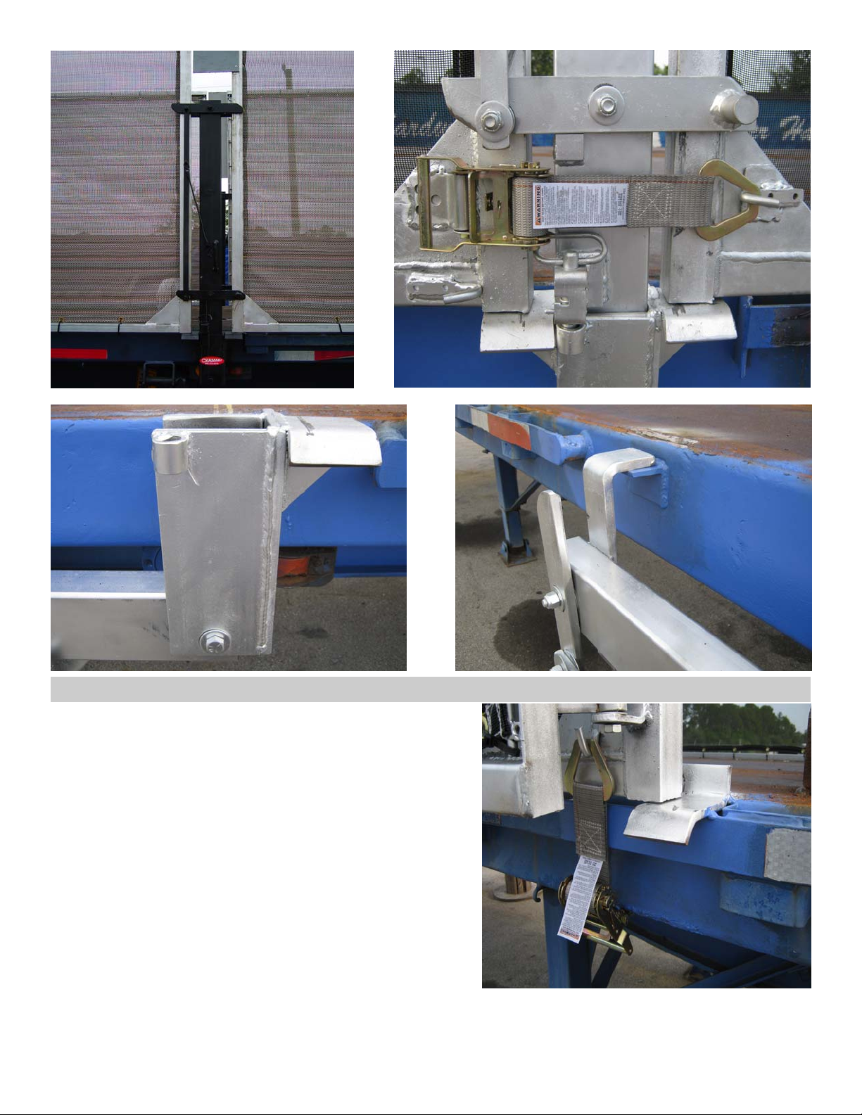
Mount Gate Locking Devices
The Gate Locking Device is positioned in the middle of the trailer to lock the front gates and the back
gates. Once the device is positioned properly it will fold down to front of trailer on the left side and to the
rear of the trailer on the right side.
To determine the proper mounting location, find the middle point of the trailer. You may need to move
any lights in the way. On the left side mark a line 2 inches from the middle point toward the front of the
trailer, the back edge of the device will be 4 ½” behind that mark. On the right side mark a line 2 inches
from the middle point toward the rear of the trailer, the back edge of the device will be 4 ½” toward the
front. This will position the center of the trailer to the center of the 2”x4” mast of the locking device.
The inside to inside distance between the masts of the two locking devices’ should be between 94 and
95 inches on a 96” body (100” and 101” on a 102” body). When mounted in the correct position, the
locking device will stop the gates from entering the deck area and let them rest ¼” above the rub rail
(this will help determine whether you need to space out the swivel pocket to obtain proper resting place
of the gates).
To allow room for the device to pivot out the way you must remove some of the rub rails and pockets if
applicable. On the left side of the trailer you must remove at least 10 ½” back from the center mounting
mark and 62” forward from the center mounting mark. On the right side of the trailer you must remove at
least 10 ½” forward from the center mounting mark and 62” back from the center mounting mark. It
may be necessary to fabricate a catch for the mast of the locking device when folded down.
Using heavy tack welds affix the locking devices in place on the side of the deck. Full welding of the swiv-
el pocket will be done at a later step after the gates have been installed.
Rev 03 CCCS Install Manual 4
Mounting Gate Helper Ramps
Supplied with the system will be four gate helper ramps.
These will be positioned and welded in place directly below
each joint where the main and bi-fold gates meet. Each bi-
fold gate will be the same length. Measure the length of
the bi-fold gate section (the bi-fold is the short gate in the
assembly) and note. Once the bulkheads and gate-locking
devices are mounted, mark off 1” from both the front and
rear of the 2”x 4” mast of the locking device. This will be
where the bi-fold gates will end when closed. From that
point measure toward the front and then the back the
length of the bi-fold section. This new point will be the cen-
ter of the gate helper ramp. Weld the ramp in place so the
“stop” on the back of the ramp stops the gate at the de-
sired position and matches with the gate locking device,
keeping it from pushing into the deck area when closed.
The ramp height should be to where it holds the gate at the correct height in the closed position just
above rub rail. If necessary, fabricate a shim and/or gusset centered under the ramp.

Rev 03 CCCS Install Manual 5
Hanging the Gates
Note: Bottom of the gates should rest when closed no more than ¼” above the rub rail and slightly inward
of the rub rail. To minimize the space but allow for any inconsistencies in the rub rail (you may need to
grind off top of any post pockets to achieve minimal distance. There are two types of gate assemblies:
one will be the left-front or the right rear. The other will be the right-front or the left-rear.
If not already done, place the bulkhead hinges into the gate hinges and secure with the hinge pins. To
determine correct placement of the gates make sure the 3 hole “latch plate” is in the lower corner that it
is closest to the bulkhead and is facing outward. Lift and place one of the gates up to the bulkhead. The
gate will stop 1” away the 2”x 4” mast of the center locking device. Lift the gate in place according to the
steps above.
Once the gate is positioned properly place a temporary ½” shim on the ramp of the gate-locking device
and a ¼” shim on the gate helper ramp. Ideally using a forklift, lift the gate on top of the shims and push
the gates against the stops on the locking device and on the helper ramp. The shims should “cock” the
gate so the bottom hinge is toward the inside and the top hinge is toward the outside of the trailer. This
will tighten up any slack in the hinges and keep the gate from drooping once the gate is utilized. (Shims
noted are typical for an install on a 48’ trailer, adjust as necessary).
Position the bulkhead hinges so the flat part is flush to the 4 x 4 of the bulkhead. IMPORTANT: There is a
small amount of play between the bulkhead hinge tube and the hinge pin. Make sure to adjust the play
in the bulkhead hinge tube by tilting the top of EACH tube away from the trailer and the bottom of EACH
tube toward the trailer prior to welding. This will prevent unnecessary droop in the gates. Then clamp the
hinges to the side of the bulkhead. For safety, put tack welds on the hinge tubes to the bulkhead before
testing. Clear the area of all bystanders prior to testing. If safely attached to the bulkhead, lower the lift so
the gate is held by the hinges and the ramps. Remove the shims and swing the gate open a few inches.
Test that the gate operates smoothly off of and back onto the ramps. The gate should rest on ramp when
closed, but push up onto the ramp with little resistance. If you need to adjust the gate for proper place-
ment simply break tack welds, loosen the top and middle hinge clamps and adjust accordingly.
With the gate now in place, completely weld the flat bar part of the hinges to the bulkhead. When secure-
ly welded, swing the gate out and finish welding the hinges. Once the hinges are fully welded, operate the
gate to make sure it opens and closes to proper positions.
Rev 03 CCCS Install Manual 6
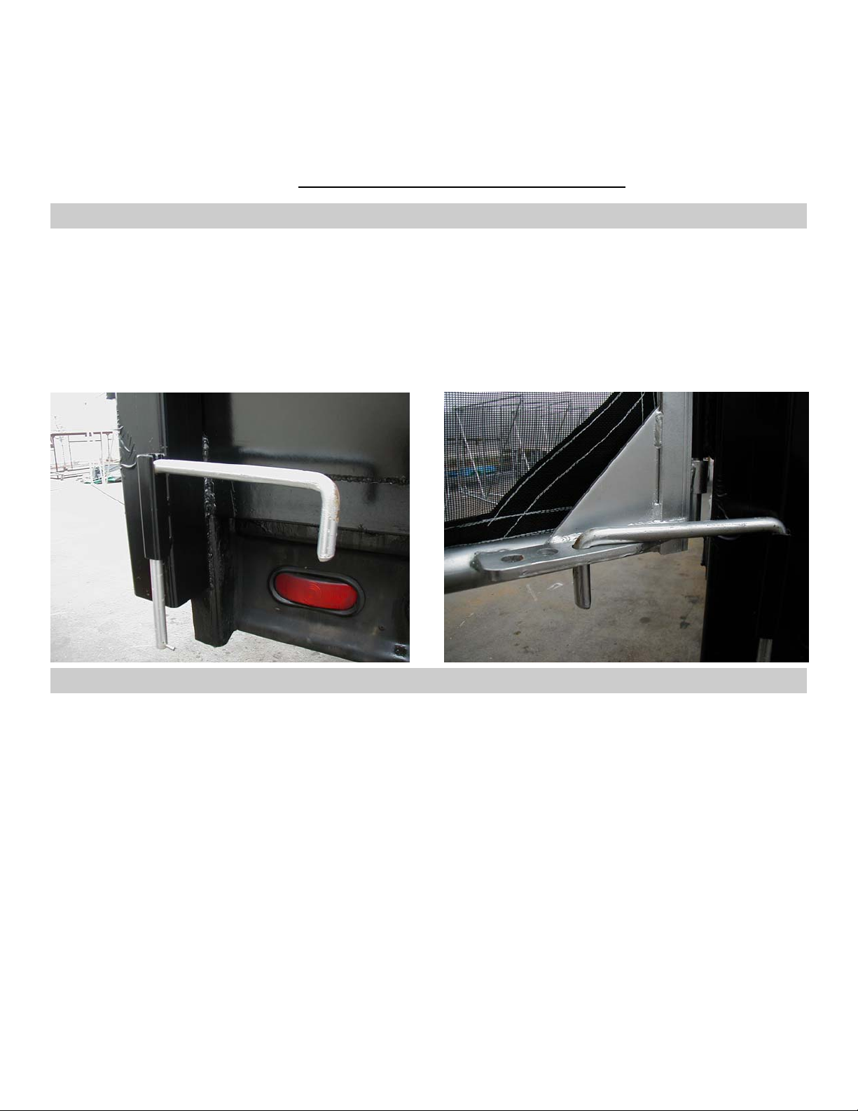
Bulkhead Locking Rods
Again, the gates should rest no more than ¼” above rub rail and stop short of the locking device mast by
1”. Repeat these steps for all other Gates.
IMPORTANT: With all the gate assemblies installed, check operation with locking device. If adjustment is
needed with the gates out of the way break the tack welds on the device(s) and reposition. Once desired
operation is achieved, at this time complete the full welding of the locking device to the deck.
The ¾” gate locking rods are to be seated into the pockets and welded to the bulkheads (one on each
outside corner). Simply place the rod through the pocket and insert the roll-pin into the hole of the rod.
Make sure the pin does not keep the rod from swinging fully around to outside of truck. When not holding
a gate open, the rod should be in “seat” of pocket. Position and tack in place checking for proper inser-
tion in 3-hole latch plate, then weld.
Repeat these steps for all other locking rods.
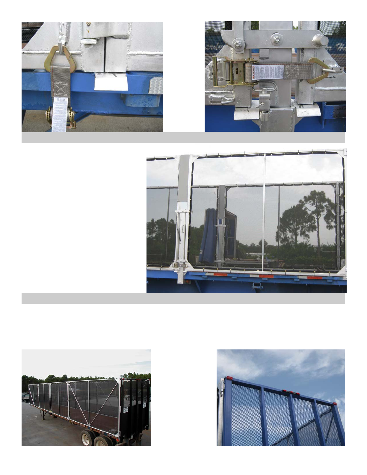
Ratchets
Mount a ratchet to the trailer directly under the “J” hook on the gusset of the bulkhead gate, to one side
of the center support ramp. You should mount the ratchet by welding the pivoting ratchet holder on the
bottom of the deck.
Weld a second ratchet to the gusset on the right rear bi-fold gate and left front bi-fold gate across from
the j-hook on the adjacent gate. Make sure the J-hook is not in the way of the pivoting action of the lock-
ing device. This ratchet will strap across the Locking Device and hook on the “J” hook securing the gates
in the closed position.
Rev 03 CCCS Install Manual 7
Center Gate Shield
Provided with the system are 2 plastic
shields and self-tapping screws. These
are used to fill the gaps between the bi-
fold gates. They should be mounted on
the rear angle of both front bi-fold
gates, flush with the top of the gates.
These must be mounted to front gate
assemblies to prevent wind damage. A
small gap must remain between the
bottom edge of the shield and the top
of the locking device mast to allow the
pivoting lock plates to function.
Lights and Reflective Tape (To Meet Federal Lighting Standards)
1. Reflective tape is required on the rear top corners of the bulkheads.
2. Amber lights are required at the top corners in the front.
3. Red lights are required at the rear top corners, and the triple light bar is required at the center top
rear. Access holes are precut in bulkhead tubes to help facilitate wiring.
Images shown
without required
reflective tape

Rev 03 CCCS Install Manual 8
Containment Tarps
Each system will have: 8 tarps (4-Lrg and 4-Sm) for a Bi-Fold system. Make sure when hanging tarps that
the webbing is to the inside. Using the plastic tie wraps supplied, tie each tarp loosely to each gate (at
this time only tie a few to get the tarps in place). Once you’ve determined the tarps are on correctly at-
tach remaining ties still leaving loose, utilizing every grommet around the tarp. Once in place, pull the
lower ties tight first, then each side and lastly the top ties tightly. Cut-off the excess length of the tight-
ened tie is desired. There should be minimal gap if any, between tarp and frame.
Chains
Provided with the system is 80” of 3/8” plated chain. This is to be attached to the main gate to stabilize
the bi-fold gate when it is opened. Cut chain into four equal pieces. Attach one end of the chain to the
lower horizontal tube of the main gates approximately 6” away from the 3-hole latch plate. Weld a j-hook
on the side of the trailer to secure the chain when not in use.
Finishing
Mask all of the lights on the trailer to prevent overspray when painting frame and bulkhead. Mask and
paint front and rear bulkheads using a direct to metal paint.
Grease hinge pins.
OPERATION
To open system: Release safety ratchet on the locking device. Then use the pivoting latch plate to re-
lease the bi-fold gates from the locking device. Open bi-fold gates up to main gates and secure with
chains. Release ratchets at the joints of the gate sections and open the folded sections to the bulkhead
and secure using the bulkhead locking rods. Reverse steps to close.
SAFETY/MAINTENANCE
When installing your system, use OSHA approved ladders or scaffolding when working above ground level.
1. Be careful of existing debris on the truck bed.
2. Keep clothing and body parts clear of any moving parts while operating the system.
3. Grease hinge pins at least twice per year.
4. Take necessary safety precautions to secure components during installation.
Table of contents
Other Cramaro Automobile Accessories manuals


Popular Automobile Accessories manuals by other brands


ULTIMATE SPEED
ULTIMATE SPEED 279746 Assembly and Safety Advice

SSV Works
SSV Works DF-F65 manual

ULTIMATE SPEED
ULTIMATE SPEED CARBON Assembly and Safety Advice

Witter
Witter F174 Fitting instructions

WeatherTech
WeatherTech No-Drill installation instructions

TAUBENREUTHER
TAUBENREUTHER 1-336050 Installation instruction