Cramaro GALOPPINO Parts list manual

CRAMARO TS S.r.l. / COLOGNAV.TA(VR) VIAQUARI DESTRA71 TEL. 0442/411688 / FAX 0442/411690
E-MAIL info@cramaro.com WEB : http://www.cramaro.com
Pag 1
TS
S.r.l.
CRAMARO TS S.r.l. COLOGNAV.TA(VR)VIAQUARI DESTRA71 TEL. +39-0442/411688 / FAX +39-0442/411690
E-MAIL info@cramaro.com WEB :
http://www.cramaro.com
“ GALOPPINO “
TECHNICAL SPECIFICATIONS FOR UTILISATATION and ASSEMBLY
FOR HANDLING SYSTEM WITH DRIVIING ARC
COLOGNA VENETA ( VR )
SISTEMI DI COPERTURA BREVETTATI

GALOPPINO
USAGE AND MAINTANENCE MANUAL
Manual n
o.
Ed. Date Pag.
MCA1001-EN-ED05 05 12/09/14 2/31
This document is the property ofCRAMAROTS s.r.l. and cannot be reproduced, even if only partially, without the written authorisation
of the company
Pag 2
CERTIFICATION
The abovementioned plant conforms to the “Machine” 2006/42 EC Directive, as amended, as well as Directive
2006/28 relating to the electro-magnetic compatibility (for its variation to electrical handling) and is subject to EC
branding.
STRUCTURE OF THE MANUAL
The customer should read the information shown in this manual very carefully, as the correct utilisation and
maintenance constitute the basis of the Customer - Manufacturer relationship.
CRAMARO ITALI S.r.l. shall not consider itself responsible for snags, breakages or accidents due to a lack of
compliance or non-application of the indications contained in this manual.
PURPOSE AND CONTENT
The purpose of this manual is to provide the necessary information to the Customer in order that, other than
appropriate utilisation of the plant, they are able to operate it in the most autonomous and safe manner possible.
The manual includes inherent information, such as the technical aspect, maintenance, spare parts and safety.
Before conducting any operation on the machine, the operators and Qualified
Personnel must read the instructions contained in this manual carefully.
In the case of doubts about the correct interpretation of the instructions, kindly call your nearest assistance
centre to obtain the necessary clarifications.
Any operative methodology of the plant not included in this instruction manual is to be considered as incorrect or
improper.
RECIPIENTS
The abovementioned manual is directed at: the Operator and Qualified Personnel appointed to maintain the
plant.
It is specified that “OPERATOR” means the personnel assigned to make the plant function and carry out the
ongoing maintenance.
“QUALIFIED PERSONNEL or QUALIFIED OPERATOR” means those persons who have attended
specialisation and training courses, etc., and have experience in connection with the installation,
commissioning, maintenance and repairs of the plant.
CONSERVATION
This instruction booklet and all the publications attached thereto must be kept in an accessible place, known to
all the operators and personnel authorised for maintenance.
ASSISTANCE CENTRES
The Customer is kindly requested to refer directly to the manufacturer for any needs relating to the use of the
plant, maintenance or to request spare parts, specifying the identifying data of the machine.
CRAMARO TS
S.r.l.
Registered and operational office 37044 Cologna Veneta ( VR ) ITALY via Quari Destra 71
Tel
0039 – 0442 –
411688
-------
Fax
0039 – 0442 –
411690
CRAMARO TS S.r.l. reserves the right to change the documentation without updating that issued, if
necessary.

GALOPPINO
USAGE AND MAINTANENCE MANUAL
Manual n
o.
Ed. Date Pag.
MCA1001-EN-ED05 05 12/09/14 3/31
This document is the property ofCRAMAROTS s.r.l. andcannot be reproduced, even if only partially, without the written authorisation
of the company
Pag 3
DESCRIPTION OF THE PRODUCT
Officially created in 2007, the GALOPPINO handling system does not set out to be a substitute but rather as
an ALTERNATIVE to the innumerablevariants of the well-known CABRIOLE’ tarpaulin.
The new CRAMARO tarpaulin, called “GALOPPINO“, groups together the best characteristics of the well-
known CABRIOLE’ tarpaulin from which it inherits both the supporting structure of the canvas, or rather the
SLIDING ARCHS that allow simplicity of assemblyand maintenance.
Nevertheless, differing from the CABRIOLE’ tarpaulin, it neither has the tarpaulin pulling system, to be fixed in
front of the box structure with the consequent bulk problems that are sometimes irresolvable, if not resorting to
using complex deviation systems of the pulling cables, and not even the double pulling cables with ring
closures, that are classic with a CABRIOLE’tarpaulin.
In fact the last arc of the GALOPPINO tarpaulin also incorporates its own motorisation
The great advantages of the GALOPPINO tarpaulin are mainly:
Easy assembly of the tarpaulin as it does not require laborious transformations of the box on
which the tarpaulin must be applied;
Very rapid assembly given the demands of the pieces that make it up;
Very rapid replacement of anypieces damaged during use;
Possibility of removing the tarpaulin completely from the vehicle by only uncoupling the two
lateral cables that are anchored to the box bytwo simple hooks with rear couplings;
No mechanical bulk in the front of the vehicle seeing that the pulling element is integrated in
the rear arc of the tarpaulin itself;
extremely adaptable to the various boxes on the market by virtue of the GREAT width
adjustability of the various elements that make it up;
Compacted bulk of the tarpaulin, almost equivalent to the other tarpaulins of the same type;
Ease and rapidity of replacement of the main pulling element of the tarpaulin in the event of a
fault or damage. (it will be sufficient to keep an assembled arc in stock so as to immediately
replace a tarpaulin that is not functioning, meanwhile the non-functioning piece can be serviced
at a CRAMARO assistance centre);
Ease and rapidity of replacement of the intermediate elements of the tarpaulin, which usually
can be replaced without having to remove the tarpaulin from the vehicle.
DIAGRAM OF THE FRONT ASSEMBLY

GALOPPINO
USAGE AND MAINTANENCE MANUAL
Manual n
o.
Ed. Date Pag.
MCA1001-EN-ED05 05 12/09/14 4/31
This document is the property ofCRAMAROTS s.r.l. andcannot be reproduced, even if only partially, without the written authorisation
of the company
Pag 4
ADJUSTABILITY OF THE CONTROL ELEMENTS OF THE TARPAULIN
FRONT ANCHORAGE ASSEMBLY OF THE CANVAS
MOTORISED PULLING ARC
INDICATIONS FOR THE ASSEMBLY OF THE SYSTEM
There are few operations to be carried out before application of the system on a common box (which confirms
the minimum APPLICABILITY characteristics shown above) but these are essential to ensure that the work is
successfully done.
1 ) Check that the front face of the cab is not sloping or contoured in a manner such as to not permit a flat
support and therefore secure mounting of the FRONT RETURN SYSTEM.
N.B. always check before drilling, by placing assembled system close to the point where the hole for the various
fixings must be drilled and that there are no electrical wires near the holes or the point of union between the
various elements that make up the box.
GALOPPINO
USAGE AND MAINTANENCE MANUAL
Manual n
o.
Ed. Date Pag.
MCA1001-EN-ED05 05 12/09/14 5/31
This document is the property ofCRAMAROTS s.r.l. andcannot be reproduced, even if only partially, without the written authorisation
of the company
Pag 5
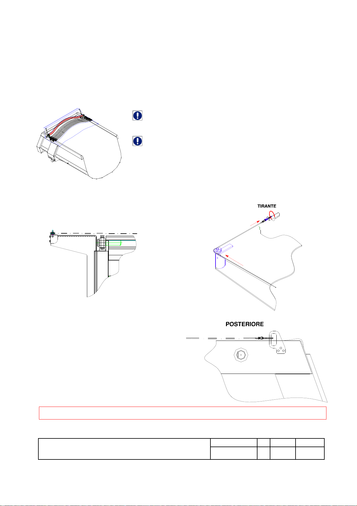
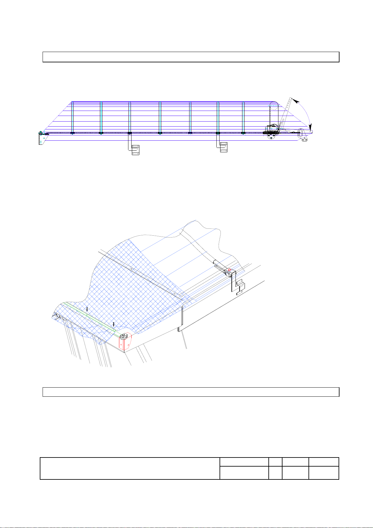
POSITIONING OF THE CANVAS AND ASSEMBLY WITH THE ACCESSORIES
The tarpaulin is normally supplied PRE-ASSEMBLED, or rather with the arcs already inserted
in the canvas, electrical connections already incorporated, the power supply cable already
inserted in the appropriate pocketwithin the tarpaulin andwith the various lateral anchorage
systems already assembled and ready to be fitted on the box.
DIAGRAM OF
CANVAS
POSITIONING PACKAGED ON THE BOX
Bind the canvas pack and arcs with a cord at the centre to avoid it
coming loose during the subsequent operations.
Turn the canvas pack over and position it on the box placing the
FLAP with the springs towards the rear edge.
Then proceed with attaching the front return systems and the rear
hooking kit.
(see diagrams)
FRONT
TENSIONROD
REAR
GALOPPINO
USAGE AND MAINTANENCE MANUAL
Manual n
o.
Ed. Date Pag.
MCA1001-EN-ED05 05 12/09/14 6/31
This document is the property ofCRAMAROTS s.r.l. andcannot be reproduced, even if only partially, without the written authorisation
of the company
Pag 6
FF
The height of the front cables is automatically determined by the fixed position of the front return
pulleys, while in the rear part of the box, the cable supports must be positioned so that the cable
remains more or less at the height of the higherwire on the edges.
In this way, when the tarpaulin is completely compacted the cables both remain slightly below the
higher profile of the edges, thus becoming less subject to damage during the loading and unloading
phases of the vehicle.
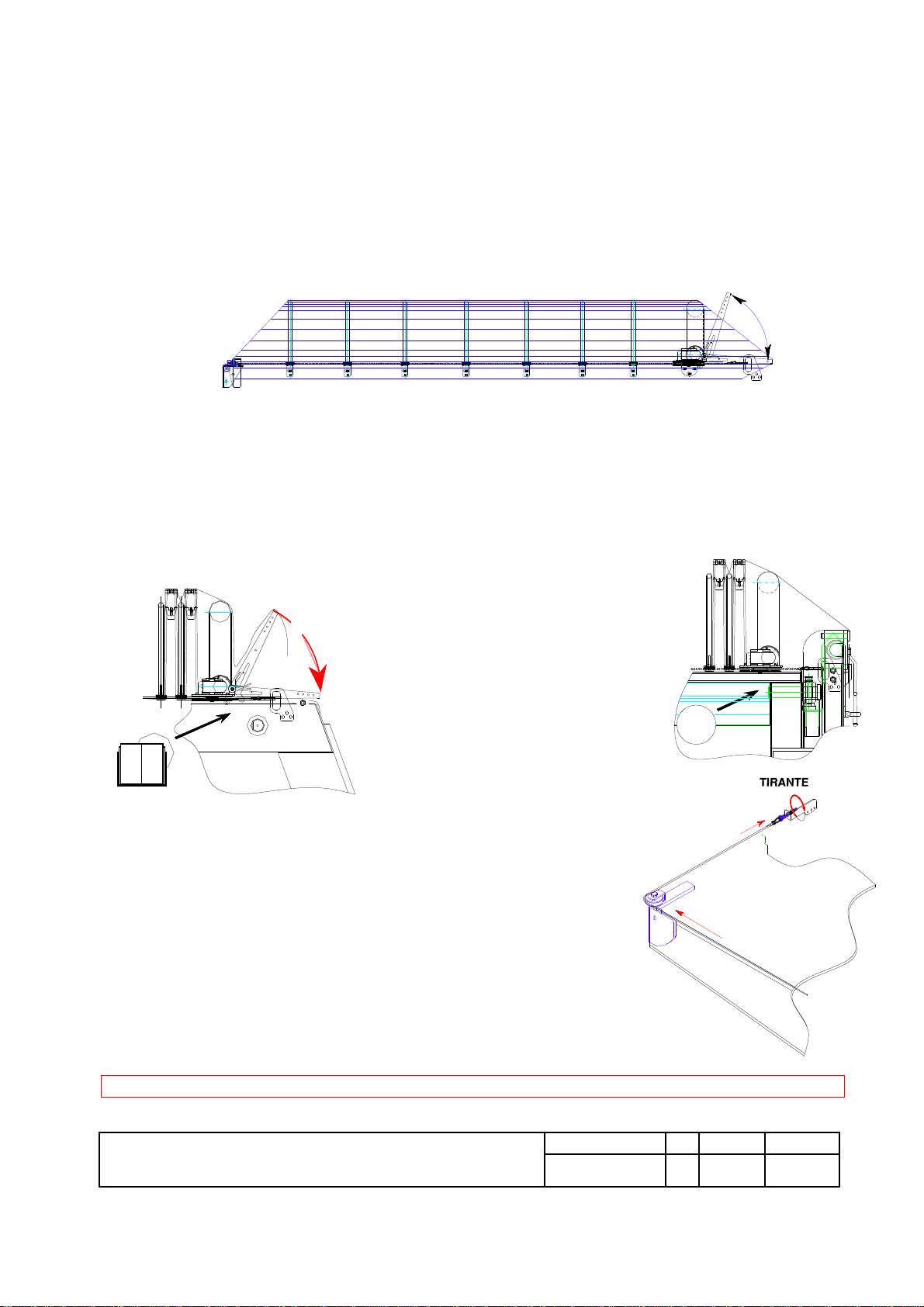
After having fixed the cables in the rear hooks unravel the tarpaulin completely by supplying
current to the system and taking the motorised arc near to the rear of the box.
Spread the canvas thus assembled over the box by cautiously activating the (electric) movement until the last
arc of the tarpaulin is sent to the rear rebate ( 1) ( 2)
( 1) Check the rotation of the FLAP so that it falls exactly in line with the rear door.
( 2) If instead the tarpaulin has a “STANDARD REAR TAIL“ then position the motorised arc in the rearmost
position.
Assembly Assembly
with FLAP without FLAP
Then tighten the cables by using the system
of the front stays.
Check that the tensioning of the lateral cables is equal on both of the cables.
The check is conducted operatively by activating the opening and closing
movement of the tarpaulin itself; during this first test check that the
pulling cables do not slip on the central pulleys of the arc motor and that
these move in a uniform manner.
ATTENTION: THE CABLES MUST NOT BE TOO TIGHT AS
OTHERWISE MOVEMENT WOULD BE DIFFICULT AND THE
CABLES WOULD DETERIORATE QUICKLY.
Once the SLIDING cables of the tarpaulin have been provisionally tightened, one can
proceed with the complete assembly of the electrical system and the control unit of the tarpaulin.
TENSION ROD

GALOPPINO
USAGE AND MAINTANENCE MANUAL
Manual n
o.
Ed. Date Pag.
MCA1001-EN-ED05 05 12/09/14 7/31
This document is the property ofCRAMAROTS s.r.l. andcannot be reproduced, even if only partially, without the written authorisation
of the company
Pag 7
1
2
3
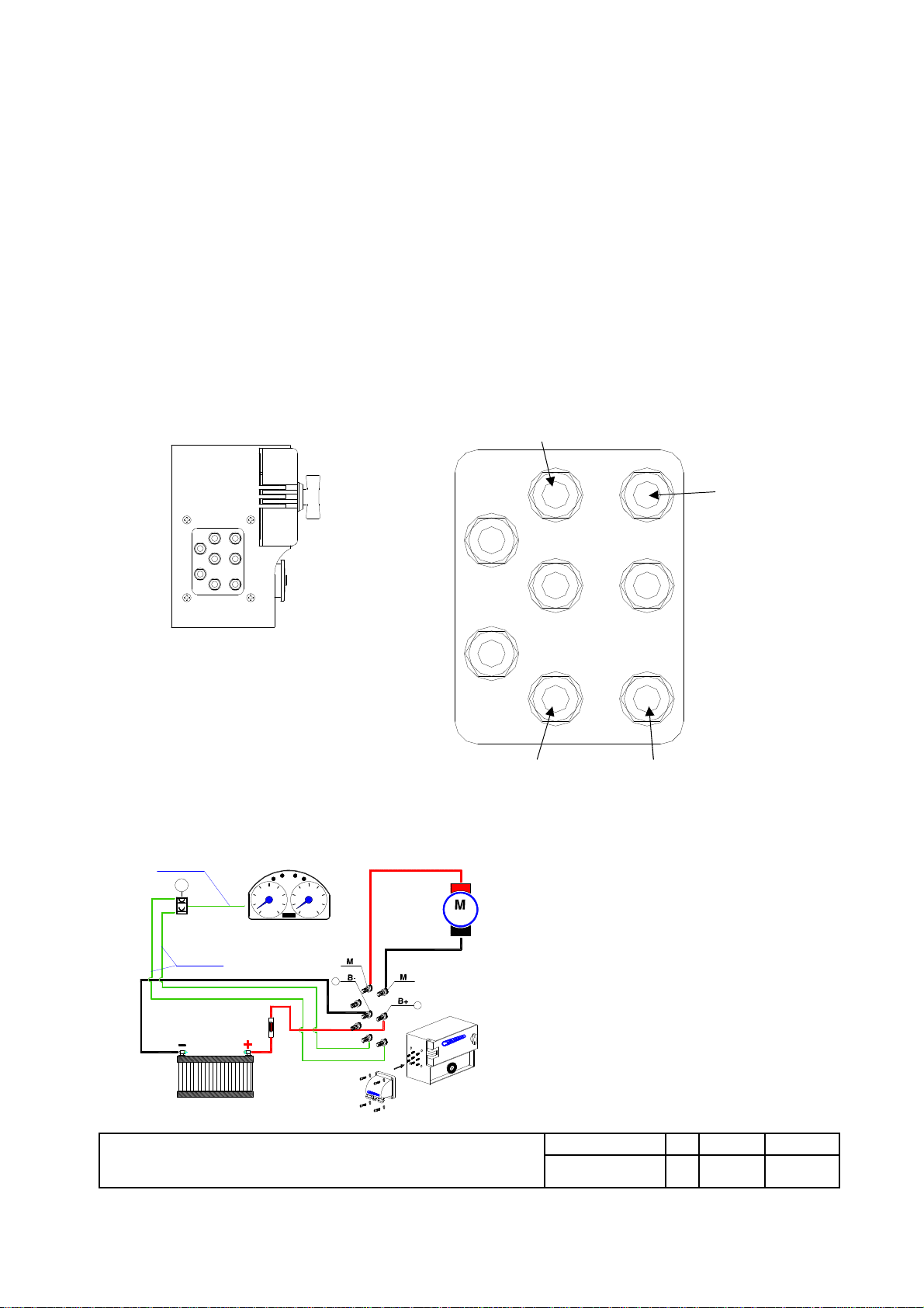
STD. CONTROL UNIT CODE 4WCE4C03031A
CONNECTION DIAGRAM
TO THE MOTOR
TO THE MOTOR
TO THE CONTROL
UNIT
1) CONTROL UNIT
2) BATTERY POWER SUPPLY CONNECTOR 3 ) ELECTRIC CONTACTS UNIT
CONTROL UNIT ELECTRICAL CONNECTION DIAGRAM
The control unit has 4 connection elements, 2 for the motor
and 2 for the battery. The connection must be carried out with two
electric cables, one of which is directed to the tarpaulin's motor,
while the other one is to the power supply circuit. Both cables are
tightened with cable glands inserted in a plastic boss with
a water-repellent gasket.
CONNECTION DIAGRAM
– CONNECTION:
Staple the FASTON cables with eyelet
on the cable whose insulation
has been removed beforehand.
Insert the FASTON cables
as shown in the figure and tighten the nuts.
Attach the plastic boss
with the 4 screws supplied and
tighten the CABLE-GLANDS.
12V 24V
GALOPPINO
USAGE AND MAINTANENCE MANUAL
Manual n
o.
Ed. Date Pag.
MCA1001-EN-ED05 05 12/09/14 8/31
This document is the property ofCRAMAROTS s.r.l. andcannot be reproduced, even if only partially, without the written authorisation
of the company
Pag 8
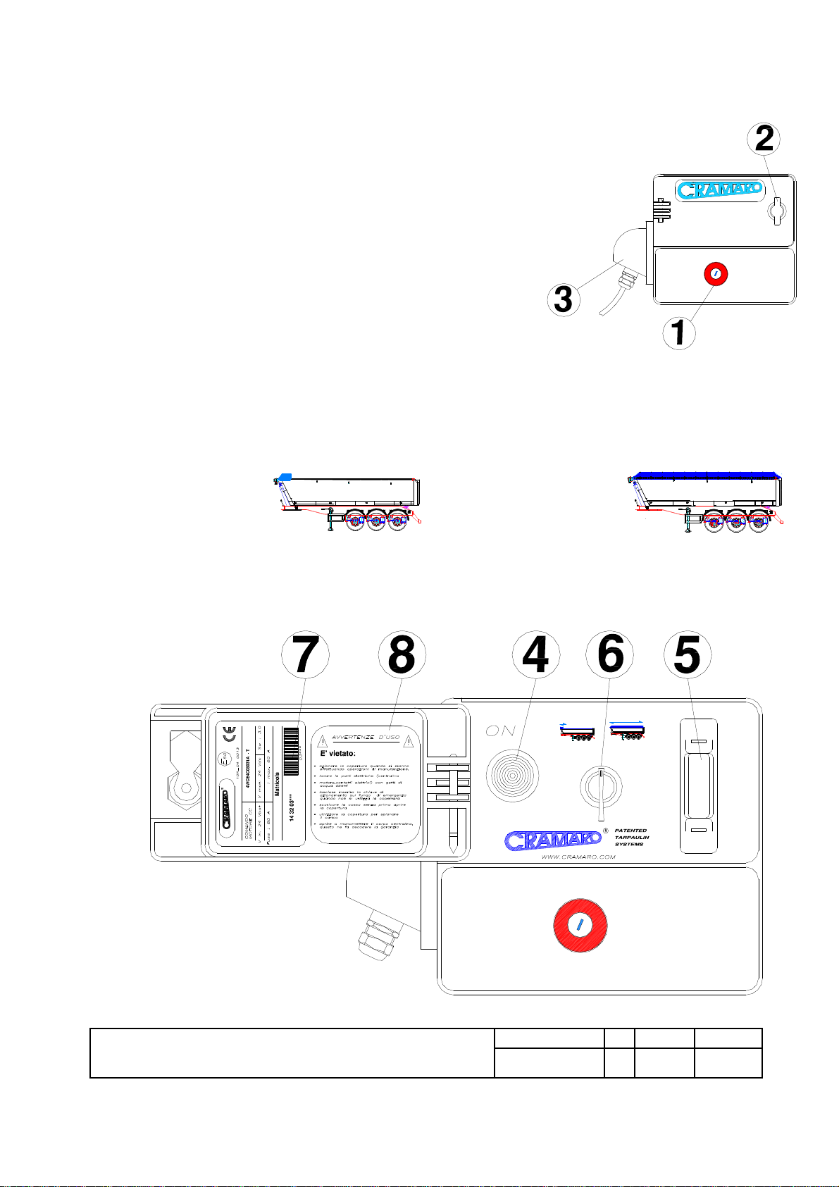
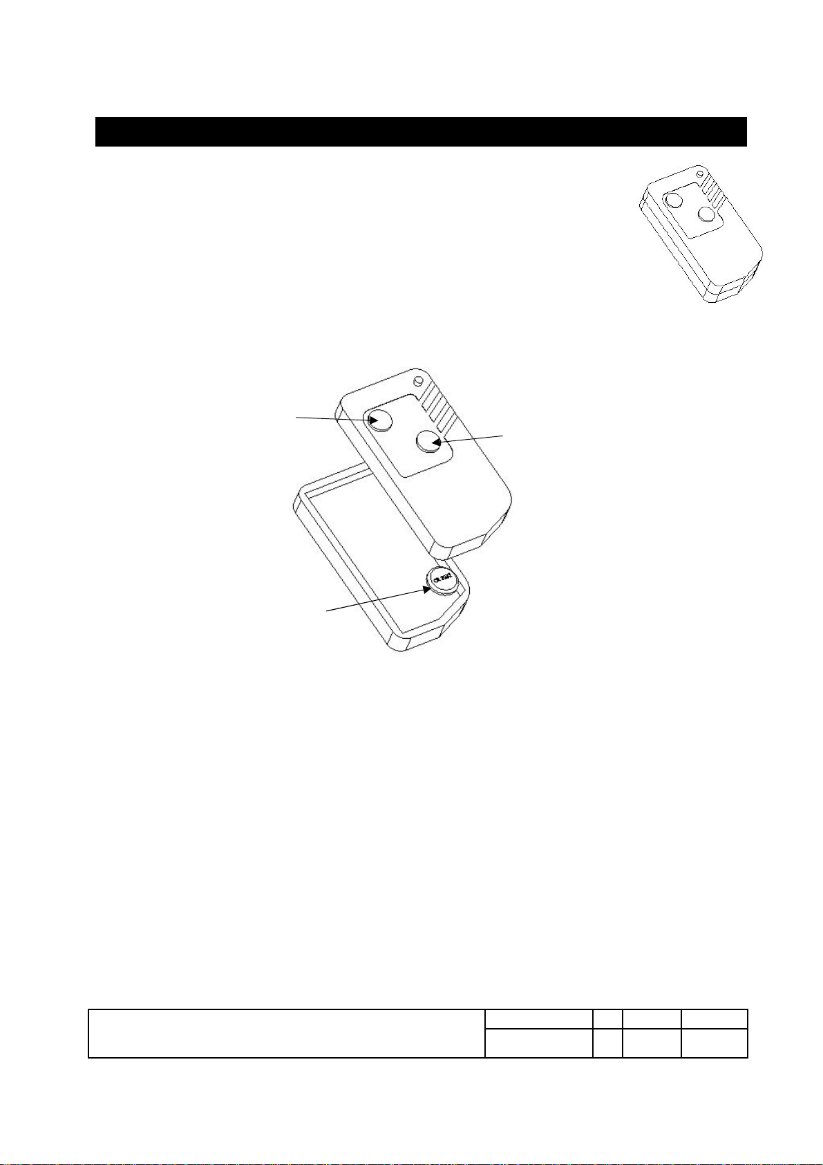
The control unit contains the following:
1emergency “MUSHROOM-SHAPED“ button
also used to start the control unit
( with REMOVABLE keys )
2Knob to open the door
that protects the control panel
3 Boss to protect electrical connections
Inside the cover of the control unit, instead, the control panel contains the following :
4Red warning light, on when the tarpaulin is moving
580 A fuse
6Spring-loaded operating switch:
- OPENING -
- CLOSING -
INTERNAL VIEW OF THE CONTROL PANEL
CRAMAR
RCRAMA
GALOPPINO
USAGE AND MAINTANENCE MANUAL
Manual n
o.
Ed. Date Pag.
MCA1001-EN-ED05 05 12/09/14 9/31
This document is the property ofCRAMAROTS s.r.l. andcannot be reproduced, even if only partially, without the written authorisation
of the company
Pag 9
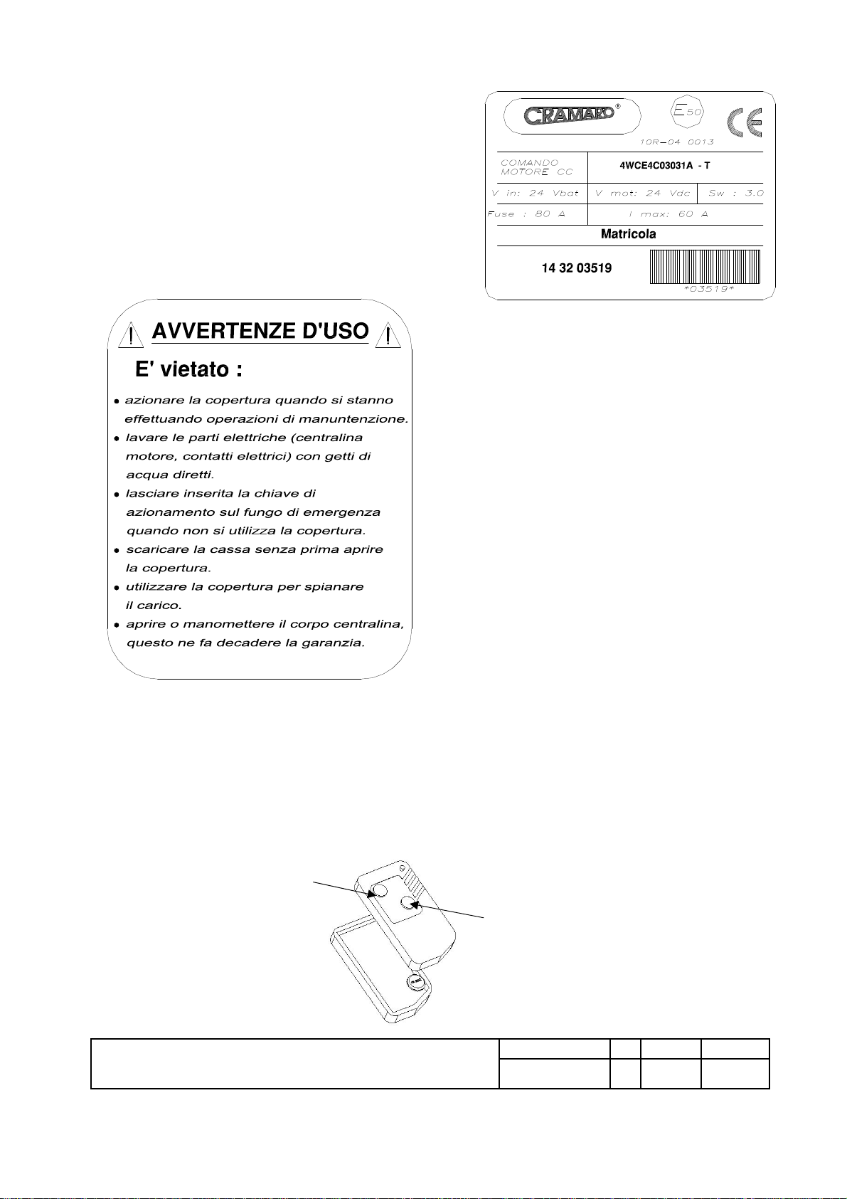
7Identification plate for the
control unit featuring the SERIAL NUMBER
(to be reported to Customer Service).
OPERATING WARNINGS
It is forbidden:
•to activate the cover when maintenance is
being performed.
•to wash electrical parts (control unit, motor,
electrical contacts) with direct jets of
water.
•to leave the activation key on the
emergency button when the cover is not
being used.
•to unload the box without first opening the
cover.
•to use the cover to smoothen the load.
•to open or tamper with the control unit
body, this renders the warranty null and
void.
8 Plate reporting the WARNINGS
.
indicating all of the most important instructions on using the
tarpaulin
N.B.
Thenewcontrolunit code
4WCE4C03031A
only works with the new transmitter code
405330211220
.
A
D
TRANSMITTER CODE
405330211220

GALOPPINO
USAGE AND MAINTANENCE MANUAL
Manual n
o.
Ed. Date Pag.
MCA1001-EN-ED05 05 12/09/14 10/31
This document is the property ofCRAMAROTS s.r.l. andcannot be reproduced, even if only partially, without the written authorisation
of the company
Pag 10
TEST FUNCTIONS
The test function is useful to verify and diagnose the operation of the control unit
and the connection of the wiring during installation, even with the motor
disconnected. After having powered the control unit, having implemented the
learning process of the remote control and accessed the test function, you can
check the operation by selecting the button (or selector) that opens or closes the
cover; if the red LED inside the cover is on, the control unit and all the wiring is
working correctly.
For the control unit to be made active and operative, it is MANDATORY to switch
off and on by pressing the (red) mushroom-shaped emergency button.
The procedure to perform this kind of test is:
1.Press the (red) mushroom-shaped emergency button to switch the device off and wait at
least 1 second
2.Release the (red) mushroom-shaped emergency button to switch the device on again
3.Within 3 seconds after start-up, press buttons A and D on the remote control
simultaneously until the LED will light up for about 100 ms (wait for about 3 s). This
means that the control unit has is entered the learning mode.
4.Release buttons A and D on the remote control and wait at least 1 second; within 10
seconds, in the control unit learning mode, activate the test function.
5.Activate the test function as follows: press and hold the D button on the remote control
until the LED will be activated with two consecutive pulses of about 100 ms to indicate
that the control unit has successfully performed the function and exited the learning
mode
6.Select the cover opening or closing button (or selector) to verify operation. If the red
LED inside the cover is on, the control unit is running.
7.Switch the control unit off and on to make it active and operative by pressing the
(red) mushroom-shaped emergency button.
In the learning mode, the control unit can only perform one function at a time. The test
function cannot be enabled unless the remote control code is first saved.
Once you enter the learning mode, the control unit, will wait 10 seconds for a function to be
executed (learning-test-deletion). If no action is launched, once the 10 seconds elapse, the
LED will be activated with two consecutive pulses of about 100 ms and the control unit
will automatically exit the learning mode. When the control unit exits the learning mode, it
is automatically operational.

GALOPPINO
USAGE AND MAINTANENCE MANUAL
Manual n
o.
Ed. Date Pag.
MCA1001-EN-ED05 05 12/09/14 11/31
This document is the property ofCRAMAROTS s.r.l. andcannot be reproduced, even if only partially, without the written authorisation
of the company
Pag 11
Identify the new control unit CODE 4WCE4C03031A by looking at the label inside the
cover. The serial number is written in the lower left part and only a barcode is present
compared to the previous version
NEW LABEL
OLD LABEL
The control unit learning procedures are compatible with the 4-button remote control as
well as the 2-button remote control.
GALOPPINO
USAGE AND MAINTANENCE MANUAL
Manual n
o.
Ed. Date Pag.
MCA1001-EN-ED05 05 12/09/14 12/31
This document is the property ofCRAMAROTS s.r.l. andcannot be reproduced, even if only partially, without the written authorisation
of the company
Pag 12
FULL OPTIONAL CONTROL UNIT CODE 4WCE4C03032A
The controller unit called "FULL OPTIONAL" integrates the STD with the following additional
commands:
-PARTIAL OPENING (timed)
-CONTROL IN CABIN
-PARTIAL OPENING + CABIN CONTROL
-CONTROL FOR VIBRATOR
The FULL OPTIONAL control unit is only available with the 24V version
WIRING CONNECTION DIAGRAM
M
M
M=motor
AUX B=battery
CC=cabin control
B- B+ AP=partialopening
AUX=vibratorcontrol
+AP
CC CC
WIRING CONNECTION CONTROL DIAGRAM IN CABIN FOR DRIVING
IC= switch in the cabin, normally open and
with the positive connected in power (e.g.
on the dashboard)
FUSE
24 V dc
IC
MOTOR
MOTOR
MOTOR
BATTERY
+
BATTERY
−
2 x 2 mm2
2 x 2 mm2

GALOPPINO
USAGE AND MAINTANENCE MANUAL
Manual n
o.
Ed. Date Pag.
MCA1001-EN-ED05 05 12/09/14 13/31
This document is the property ofCRAMAROTS s.r.l. andcannot be reproduced, even if only partially, without the written authorisation
of the company
Pag 13
WIRING CONNECTION CONTROL DIAGRAM IN CABIN FOR SEMI-TRAILER
IC= switch in the
cabin, normally
open and with the
positive
connected in
power (e.g. on the
dashboard)
WIRING
CONNECTION DIAGRAM FOR PARTIAL OPENING (TIMED 7 s)
IC = command from
PTOs with positive
connected in power
(e.g. on the
dashboard)
−
+
BATTERY
MOTOR
BATTERY
MOTOR
FUSE
24 V dc
IC
MOTOR
2 x 2 mm2
2 x 2 mm2
FUSE
24 V dc
IC
MOTOR
MOTOR
MOTOR
BATTERY
+
BATTERY
−
+

GALOPPINO
USAGE AND MAINTANENCE MANUAL
Manual n
o.
Ed. Date Pag.
MCA1001-EN-ED05 05 12/09/14 14/31
This document is the property ofCRAMAROTS s.r.l. andcannot be reproduced, even if only partially, without the written authorisation
of the company
Pag 14
FUSE
24 V dc
MOTOR
MOTOR
MOTOR
BATTERY
+
BATTERY
−
WIRING CONNECTION DIAGRAM FOR VIBRATOR CONTROL
RELAY
The RELAY to be used to control the vibrator is the E T106A2 model of RAVIOLI
A 4-CHANNEL TRANSMITTER must be used to use the VIBRATOR CONTROL
B
A
D
C
Button A : cover activation - OPENING function
Button B : cover activation - CLOSING function
Button C : VIBRATOR activation
Button D : cover activation - CLOSING function (same function as button B)
GALOPPINO
USAGE AND MAINTANENCE MANUAL
Manual n
o.
Ed. Date Pag.
MCA1001-EN-ED05 05 12/09/14 15/31
This document is the property ofCRAMAROTS s.r.l. andcannot be reproduced, even if only partially, without the written authorisation
of the company
Pag 15
RADIO CONTROL (optional)
The control unit must be configured correctly to be able to use the radio
control. Below are the steps to recognise and save one or several radio
controls.
Learning how to use the Remote Control
The control unit can learn, i.e. it can recognise and save, a new remote
control. The control unit can associate up to 5 remote controls. When an
additional remote control is recognised and saved the oldest one is deleted.
A
D
1
Button A : cover activation - OPENING function
Button D : cover activation - CLOSING function
1 – battery CR 2032

GALOPPINO
USAGE AND MAINTANENCE MANUAL
Manual n
o.
Ed. Date Pag.
MCA1001-EN-ED05 05 12/09/14 16/31
This document is the property ofCRAMAROTS s.r.l. andcannot be reproduced, even if only partially, without the written authorisation
of the company
Pag 16
Proceed as follows to recognise and save a new remote control:
1. Press the (red) mushroom-shaped emergency button to switch the device off and
wait at least 1 second
2. Release the (red) mushroom-shaped emergency button to switch the device on
again
3. Within 3 seconds after start-up, press buttons A and D on the remote control
simultaneously until the LED will light up for about 100 ms (wait for about 3 s). This
means that the control unit has is entered the learning mode.
4. Release buttons A and D of the remote control and wait at least 1 second;
within 10 seconds, in the control unit learning mode, activate the save function
of the remote control.
5. Save the remote control code: press and hold the A button on the remote control
until the LED will be activated with two consecutive pulses of about 100 ms to
indicate that the control unit has successfully performed the function and exited the
learning mode.
Repeat the steps above to recognise and save a new remote control..
IMPORTANT NOTE : You can only add one remote control at a time.
Deleting from the Control Unit Memory
The control unit's memory, used to recognise the remote controls, can be erased at any time.
Proceed as follows to erase the control unit's memory:
1. Press the (red) mushroom-shaped emergency button to switch the device off and
wait at least 1 second
2. Release the (red) mushroom-shaped emergency button to switch the device on
again
3. Within 3 seconds after start-up, press buttons A and D on the remote control
simultaneously until the LED will light up for about 100 ms (wait for about 3 s). This
means that the control unit has is entered the learning mode.
4. Release buttons A and D of the remote control and wait at least 1 second;
within 10 seconds, in the control unit learning mode, activate the code delete
function.
5. Deleting codes from the memory : press and hold the A and D buttons on the
remote control simultaneously until the LED will be activated with two consecutive
pulses of about 100 ms to indicate that the control unit has successfully performed
the function and exited the learning mode.
Replacing the operating battery
Replace the battery by opening the remote control and removing the fastening screw at the back with a
screwdriver. The battery model is CR 2032
GALOPPINO
USAGE AND MAINTANENCE MANUAL
Manual n
o.
Ed. Date Pag.
MCA1001-EN-ED05 05 12/09/14 17/31
This document is the property ofCRAMAROTS s.r.l. andcannot be reproduced, even if only partially, without the written authorisation
of the company
Pag 17
+
−
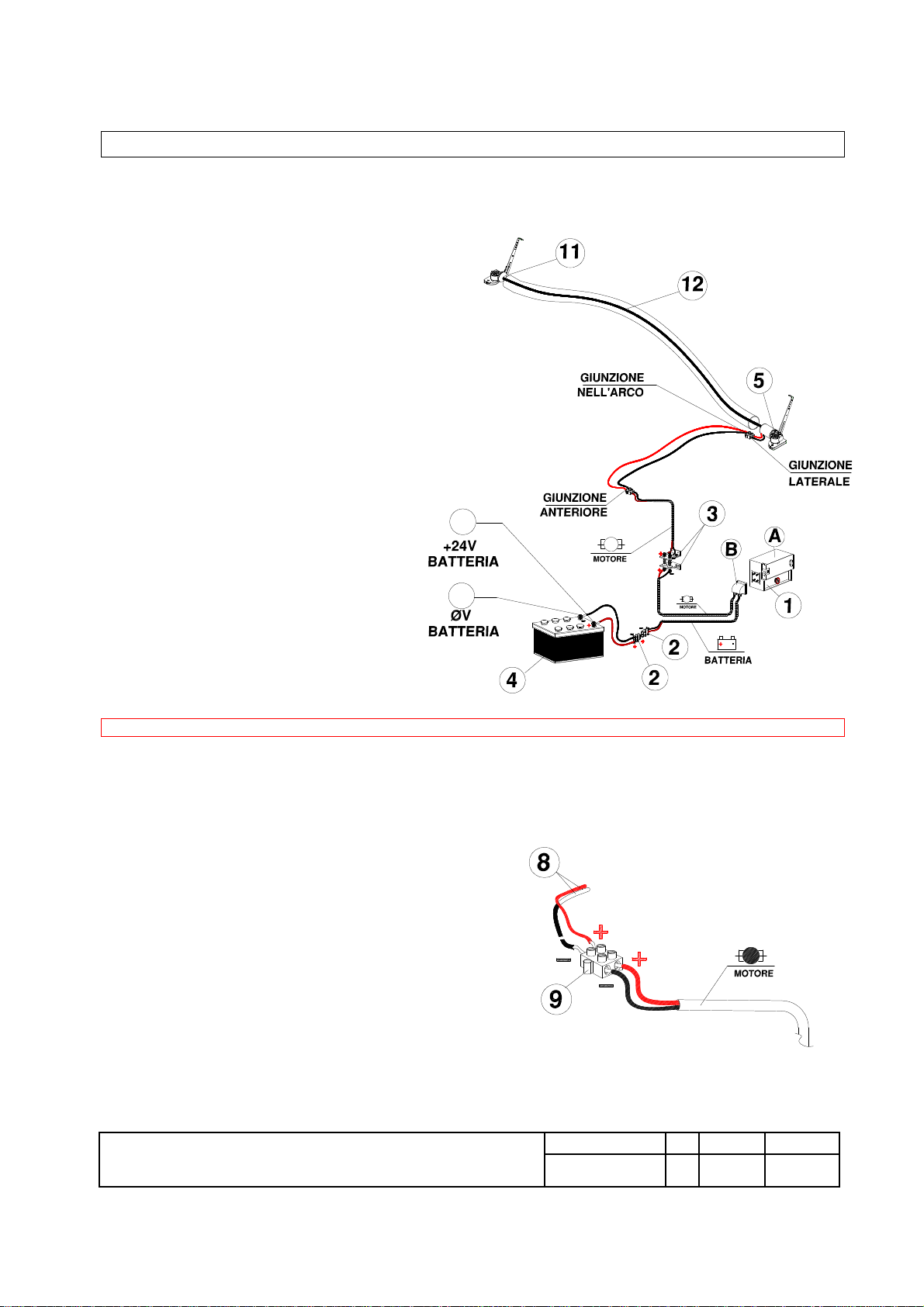
STD ELECTRICAL SYSTEM DIAGRAM
1 ) CONTROL UNIT
2 ) CONNECTION SOCKET + PLUG
3 ) ELECTRICAL CONTACTS
4 ) VEHICLE BATTERY
5 ) MOTOR REDUCTOR
6 ) LATERAL JUNCTION
8 ) 2 CABLES THAT PASS THROUGH THE ARC AND
IN THE LOWER POCKET OF THE TARPAULIN
9 ) FRONT JUNCTION
10 ) CONTROL UNIT CONNECTIONS COVER
11) REDUCER
12) ELEMENT OF TRANSMISSION REDUCERS
JUNCTIONIN ARC – LATERAL JUNCTION – FRONT JUNCTION – 24V BATTERY - MOTOR
The electrical cables (8) are inserted in the appropriate internal pocket of the tarpaulin, pas within the rear of the
arc and connected with the wires ( these also pass within the finalarc) that come from the motor placed at the
extremity of the same arc.The connection takes place through a multi-point terminal.
The control unit is usually positioned
on the side at the front of the chassis
(driver’s side) but may also be positioned
within the cab, in this case an express
request must be made in the order and the appropriate supplementary connection plugs will be provided in an
additional assemblykit.

GALOPPINO
USAGE AND MAINTANENCE MANUAL
Manual n
o.
Ed. Date Pag.
MCA1001-EN-ED05 05 12/09/14 18/31
This document is the property ofCRAMAROTS s.r.l. andcannot be reproduced, even if only partially, without the written authorisation
of the company
Pag 18
Cod 405260201010 = PLUG
Cod 405260201020 = SOCKET - HANDLE
Cod 405260202200 = ( SM ) MALE PIN (small)
Cod 405260202300 = ( SM ) FEMALE PIN (small)
CANVAS FIXING FRONT PART
Spread the tarpaulin completely above the box.
Spread, pulling the front part of the canvas gently, until it rests on the front edge of the box corresponding to the
furthestforward point possible. Fix the lateral parts of the canvas with the Teflon reinforcement (phed plate) with
the screws in the lateral supports of return mechanism; during this operation also position the pulleys protection
guard.
Finally rivet the remaining part of the canvas to the appropriate perforated aluminium plate and cut off the
excess part of the canvas.
PARTICULARS of the FRONT FIXING of the CANVAS
PHED PLATE
GUARD
PERFOIRATED ALUMINIUM PLATE
GALOPPINO
USAGE AND MAINTANENCE MANUAL
Manual n
o.
Ed. Date Pag.
MCA1001-EN-ED05 05 12/09/14 19/31
This document is the property ofCRAMAROTS s.r.l. andcannot be reproduced, even if only partially, without the written authorisation
of the company
Pag 19
ASSEMBLY OF THE LATERAL RAPID HOOKS
Laterally the “GALOPPINO’“ tarpaulin in the – A – C – versions is anchored to the box by a certain number of
automatically activating metallic fixings.
These FIXNGS called “RAPID HOOKS“ are supplied with a further safety system or else cables and lateral
elastics.
RAPID LATERAL ANCHORAGES OF THE BAYONET TYPE
The rapid hooks for the GALOPPINO tarpaulin are of the BAYONET type, and the number provided is:
2 rapid hooks per
side: A LONG and a MEDIUM hook
FINISHING OPERATIONS AND PRE-UTILISATION CHECK
When all the operations indicated on the previous pages have been completed check that the entire system is
functioning well.
•The tarpaulin must slide when opening and closing without any particular effort or sticking in its
movement.
GALOPPINO
USAGE AND MAINTANENCE MANUAL
Manual n
o.
Ed. Date Pag.
MCA1001-EN-ED05 05 12/09/14 20/31
This document is the property ofCRAMAROTS s.r.l. andcannot be reproduced, even if only partially, without the written authorisation
of the company
Pag 20
•If the tarpaulin tends to stick and/or place itself transversely on the sides it means that the RH and LH
pulling cables do not have the same tension, consequently it is indispensable to adjust the tensioners of the
cables themselves.
REPLACEMENT OF THE PULLING MOTOR OF THE TARPAULIN
The replacement of the tarpaulin motor requires a fewsimple operations and can be done without removing the
tarpaulin from the vehicle.
I. Unhook the cable from the side of the motor to be replaced and remove it from the pulleys of the motor.
II. Lock the final arc to the box so that it cannot fall off and cause accidents to the operator.
III. Remove the screws holding the motor fixed to the final arc.
IV. Extract the motor from the final arc.
V. Remove the screws keeping the motor wires connected to the cable that passes within the arc, noting
the polarity (colour of the wires)
VI. Replace the motor with a new (or reconditioned) motor
VII. Reconnect the wires to the cable that passes within the arc, paying attention to the polarity (colour of
the wires)
VIII. Replace the motor in its housing within the final arc
IX. Check the distance of the lateral mountings of the motor from the lateral sides of the box and adjust it to
the original measure (if necessary)
X. Definitively tighten the screws that hold the motor attached to the final arc.
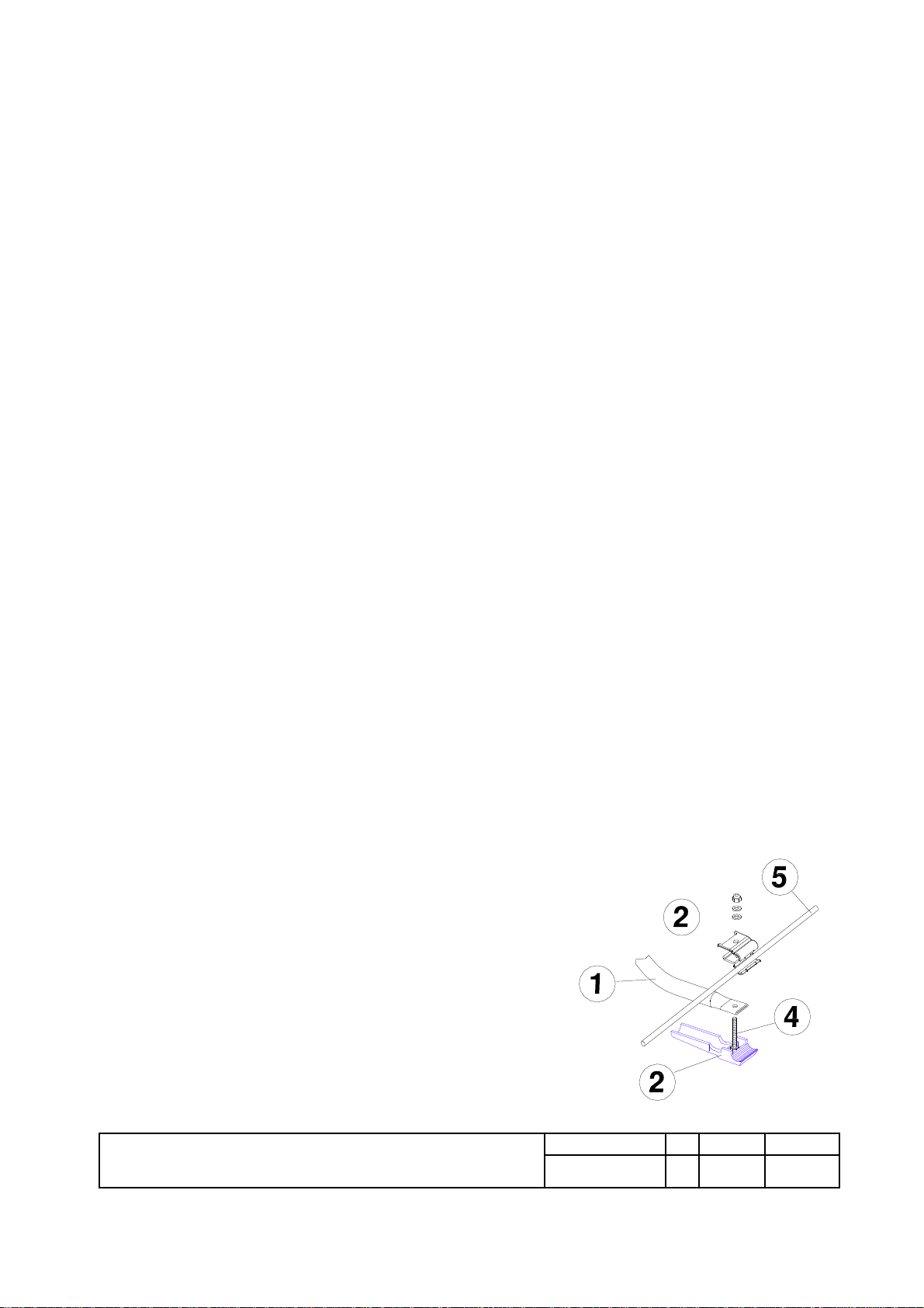
REPLACEMENT OF DAMAGED ARCS
The replacement of damaged arcs can also be carried out without having to remove the tarpaulin from the
vehicle.
If the terminal part of the arc is not damaged it is not even necessaryto remove the cables from the tarpaulin, it
will suffice once the arc to be substituted is identified to:
I. Remove the screws holding the arc fixed to the extremities equipped with a sliding shoe.
II. Undo the shoe and extract the arc from the lower pocket of the tarpaulin that normallyholds it.
III. Insert the new arc in the pocket of the tarpaulin paying
attention not to tear the tarpaulin.
IV. Refit the cables between the two elements of the
dismountable plug, fitting together the elements thereof,
and reassemble the shoe, plug and arc.
V. Check the distance of the lateral mountings of the arc from
the lateralsides of the box and adjust it to the original
measure (if necessary)
VI.
Definitively tighten the screws that hold the
shoe and
dismountable plug
attached to the arc
Table of contents
Other Cramaro Automobile Accessories manuals


Popular Automobile Accessories manuals by other brands


ULTIMATE SPEED
ULTIMATE SPEED 279746 Assembly and Safety Advice

SSV Works
SSV Works DF-F65 manual

ULTIMATE SPEED
ULTIMATE SPEED CARBON Assembly and Safety Advice

Witter
Witter F174 Fitting instructions

WeatherTech
WeatherTech No-Drill installation instructions

TAUBENREUTHER
TAUBENREUTHER 1-336050 Installation instruction