Creative Playthings Premium Pine User manual
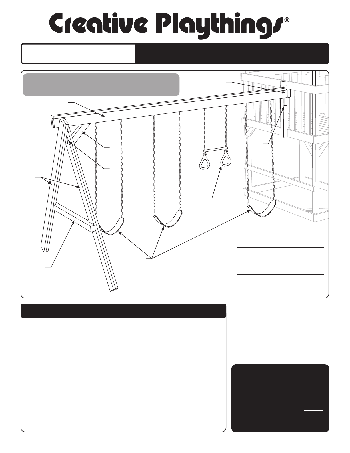
PARTS
B
A
C
D
E
F
G
J
* Not Pictured
INSTRUCTIONS
7 FT. SWING BEAM
H
This manual documents the
assembly of a 4 Position Swing
Beam. The 3 Position is similar.
See the instructions for the
Gym Tower for information on
proper ground cover.
All hardware on this set
is specially coated for
corrosion resistance.
If non-Creative Playthings
hardware is used, it MUST
be galvanized or stainless
steel.
Premium Pine 7 Ft. 4 Position Swing Beam
63058-202 4 Position Swing Beam
63059-212 7 ft Swing Beam Legs
50546-777 3 Swings, 1 Trapeze
Premium Pine 7 Ft. 3 Position Swing Beam
63061-202 3 Position Swing Beam
63059-212 7 ft Swing Beam Legs
AA934-204 2 Swings, 1 Trapeze
Parts for the optional Glider:
50545-555 Glider Bracket Pack
AA911-342 Chained Glider
A 1 40587-102 4 Position Swing Beam Assembly
OR
* 1 40586-102 3 Position Swing Beam Assembly
B 1 32620-102 Angle Brace 4 x 4 x 16-7/8"
C 1 32625-102 Leg Brace 4 x 4 x 58"
D 2 40447-102 Leg Assembly, 7ft. Swing Beam
E 1 14175-400 T-Bracket, Green
F 1 14176-400 Beam Retainer, Green
G 1 14162-400 8" L-Brace, Green
* 2 14174-400 Beam Bracket (in Hardware Bag)
* 2 36515-102 Stake 2 x 2 x 18"
H 1 40311-400 Trapeze Assembly
J 3 40321-400 Sling Swing Assembly (2 Swing for 3 Position Beam)
1 50395-720 Hardware Bag, Swing Beam
1 50400-721 Hardware Bag, 7 Ft. Swing Beam
IMPORTANT: When installing a Swing Beam to a Norfolk or Man-
chester Gym, do not install the two swing hangers closest to the
gym. The area must be kept clear for tire swing clearance.

Page 2 ©Copyright 2006, Creative Playthings. Printed in U.S.A.
19718-300 Rev C (05-20)
7 Ft. Swing Beam
ASSEMBLY INSTRUCTIONS
HARDWARE
50395-701 Hardware Bag, 5/8" Fasteners
2 12002-211 Flat Washer 5/8"
1 17123-5810 Hex Bolt 5/8 x 10"
1 12052-111 Nylock Nut 5/8"
6 17020-113 Screw #10 x 2-1/2"
50395-703 Hardware Bag, 3/8" Fasteners
18 12002-207 Flat Washer 3/8
7 12017-207 Lock Washer 3/8
4 17001-103 Weld Nut 3/8"
2 17003-1213 Hex Bolt 3/8 x 3"
2 17003-1413 Hex Bolt 3/8 x 3-1/2"
1 17003-1613 Hex Bolt 3/8 x 4"
2 17003-2013 Hex Bolt 3/8 x 5"
1 17003-3013 Hex Bolt 3/8 x 7-1/2"
6 17036-1603 Lag Screw 3/8 x 4"
3 12052-107 Nylock Nut 3/8"
2 15081-704 1" Hole Cap, Brown
50400-721 Hardware Bag, 7 Ft. Swing Beam
2 14174-400 Beam Bracket
3 15144-950 Plug, 50 Mm Square, Black
1 50299-700 Bag HD Ny-Glide Swing Hangers (6)
50299-700 Bag HD Ny-Glide Swing Hangers (6)
6 14090-100 Heavy Duty Ny-Glide Swing Hanger
12 17036-1403 Lag Screw 3/8 x 3-1/2"
12 12002-207 3/8" Flat Washer
50470-100 Creative Nameplate Bag
1 14209-100 Creative Nameplate
4 17128-202 Stainless Pan Head Screw #6 x 1/2"
In addition, the 4 position beam includes:
1 50399-700 Bag HD Ny-Glide Swing Hangers (2)
2 14090-100 Heavy Duty Ny-Glide Swing Hanger
4 17036-1403 Lag Screw 3/8 x 3-1/2"
4 12002-207 Flat Washer 3/8
Screw #10 x 2-1/2"
Hex Bolt 3/8 x 3"
Hex Bolt 3/8 x 4"
Hex Bolt 3/8 x 5"
Hex Bolt 3/8 x 3-1/2"
Lag Screw 3/8 x 3-1/2"
Lag Screw 3/8 x 4"
Flat Washer 3/8"
Flat Washer 5/8"
Lock Nut 5/8"
1" Hole Cap
Lock Nut 3/8"
Pan Head
Screw #6 x 1/2"
Lock Washer 3/8"
Weld Nut 3/8"
Hex Bolt 3/8 x 7-1/2" ( Truncated to t on page).
Hex Bolt 5/8 x 10" ( Truncated to t on page).

Page 3
©Copyright 2006, Creative Playthings. Printed in U.S.A. 19718-300 Rev C (05-20)
7 Ft. Swing Beam
ASSEMBLY INSTRUCTIONS
These Swing Mount installation instructions apply to the Williamsburg and Lexington gyms only.
Mounting instructions for the Chesapeake, Yorktown, Ridgeeld, Norfolk and Manchester gyms
are included in the assembly manual provided with those sets.
Installing Swing Mount for Williamsburg and
Lexington:
The 7 Ft Swing Beam can be mounted to any side of the
Williamsburg or Lexington Gyms, as long as no other ele-
ments conict with the swing safe play zone. The safe play
zone for the 7 Ft Swing Beam is 14' in front and 14' behind
the Beam.
Hold a Swing Mount (B) in place with one edge aligned to
the center of the Wall Support and Platform Support, above
the Safety Rail. Use a level to assure the Swing Mount is
plumb.
Mark the positions of the holes at each end of the Swing
Mount on the Wall and Platform Supports. Make sure that
the holes will not conict with other hardware. Drill 3/8"
diameter holes through the boards at each mark.
Fasten the Swing Mount to the Wall Support and Platform
Side using two 5/16 x 4" Hex Bolt Assemblies.
Note: It is best to mount the Swing Beam at the middle of
the side of a gym. Since the side of a Lexington gym is very
long, it is allowable mount the Swing Beam as close as 2'6"
to the end of the gym.
Center line of
Wall Support
STEP 1 – Mark & Drill Hole for Bracket
There are two different Swing Mount hole patterns that you
may encounter. The rst version, which is on the right, should
be treated as follows:
On the side of Swing Mount, make a mark 4-1/8" above the
top hole. Drill a 7/16" diameter hole through the mark made,
as shown. Use the 7/16" diameter drill to enlarge the other
holes indicated.
The second version, on the right, offers more exibility. Use the
Beam Retainer (F) as an aid to determine which group of three
holes to use when mounting the Swing Beam. If the ground
drops away from the gym, use the lowest combination. If there
is to be deep ground cover, use the highest combination. Use
a 7/16" diameter drill to enlarge the holes chosen.
New Hole
Beam
Retainer
7/16" diameter
Version 1 Version 2
Note: mounting the beam in the highest position may conict with
the tent pipe on the Lexington or Williamsburg tent-roof gyms.
In case of conict, mount the beam in a lower position.

Page 4 ©Copyright 2006, Creative Playthings. Printed in U.S.A.
19718-300 Rev C (05-20)
7 Ft. Swing Beam
ASSEMBLY INSTRUCTIONS
STEP 2 – Swing Hangers
It is extremely important that you read and follow in installation
procedure provided in the Swing Hanger package. The Swing
Hangers should be mounted to the underside of the Swing
Beam Assembly in the positions shown.
In the case that a Spiral Slide Direct Adapter is attached to
the Gym, a Ring Trapeze should be mounted closest to the
Gym. The optional Glider should be mounted at the end of
the Swing Beam next to the legs.
STEP 3 – T-Bracket Assembly
Insert three T-Bracket Plugs into the open ends of the T-
Bracket.
Fasten two Beam Brackets the T-Bracket (E) using one 3/8
x 3" Hex Bolt, two 3/8" Flat Washers and one 3/8" Nylock
Nut each.
H/D Ny-Glide
Swing Hangers
Swing Beam Rail
Front View
H/D Ny-Glide
Swing Hanger
Lag Screws 3/8 x 3 1/2"
with 3/8 Flat Washers
Omit these hangers
on the Norfolk or
Manchester Gym
Omit these hangers if
installing optional Glider. Gym
End
IMPORTANT: When mounting a Swing Beam to a
Norfolk or Manchester Gym. Do not install the two
swing hangers closest to the gym. The area must
be kept open for tire swing clearance.
STEP 4 – Install T-Bracket Assembly
Attach the T-Bracket Assembly to the Swing Beam using
one 3/8 x 5" Hex Bolt, two 3/8" Flat Washers and one 3/8"
Nylock Nut.
Beam Brackets
T-Bracket
T-Bracket Plug

Page 5
©Copyright 2006, Creative Playthings. Printed in U.S.A. 19718-300 Rev C (05-20)
7 Ft. Swing Beam
ASSEMBLY INSTRUCTIONS
STEP 6 - Install Swing Beam
NOTE: This step requires at least two
people to complete.
Fasten the Beam Retainer (F), the Swing
Beam Assembly (A) and L-Brace (G) to the
second hole on the Swing Mount using one
3/8 x 7-1/2" Hex Bolt Assembly, as shown.
Secure the L-Brace to the Swing Beam
using one 3/8 x 4" Hex Bolt Assembly (The
Weld Nut should be on the front of the Swing
Beam), as shown.
In order to assure that the Hex Bolts fully
engage with the Weld Nut, the Hex Bolts
used in this step are slightly longer than
necessary. Please use additional Flat
Washers if the end of the Hex Bolt extends
more than 1/8" beyond the Weld Nut.
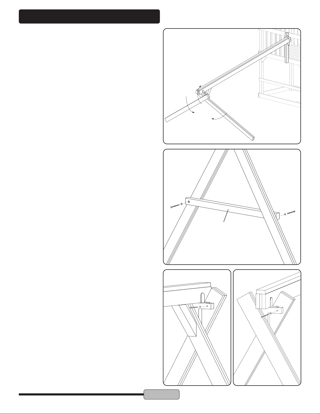
STEP 5 – Install Angle Brace & Legs
Fasten the Angle Brace (B) and two Leg Assemblies (D) to the T-Bracket Assembly using one 5/8 x 10" Hex Bolt, two 5/8"
Flat Washer and one 5/8" Nylock Nut. Do not fully tighten the Hex Bolt Assembly. Secure the Angle Brace (B) to the Swing
Beam Assembly using one 3/8 x 4" Lag Screw and one 3/8" Flat Washer.
B
D
A
Hex Bolt
3/8 x 7-1/2"
Use Additional
Flat Washers
Hex Bolt
3/8 x 4"
F
A
A
G
Page 6 ©Copyright 2006, Creative Playthings. Printed in U.S.A.
19718-300 Rev C (05-20)
7 Ft. Swing Beam
ASSEMBLY INSTRUCTIONS
STEP 7 – Raise the Swing Beam
Slowly raise the Swing Beam off the ground until the holes
from the Beam Retainer, L-Brace and the third hole from the
top end of the Corner Post line up and the Beam is level.
Position the Legs to support the Beam.
Step 8 – Leg Brace
Align the Leg Brace (C) to the Leg Assemblies. Make sure
the Leg Brace is level.
At the contact point, mark the placement of the holes of the
Leg Brace to the Leg Assemblies. Drill a 1/4" diameter hole
and 1" deep on each mark made. Fasten the Leg Brace to
the Leg Assemblies using two 3/8 x 4" Lag Screws and two
3/8" Flat Washers.
C
STEP 9 – Secure Legs to T-Bracket
Fasten the Leg Assemblies to the T-Bracket Assembly using
two 3/8 x 4" Lag Screws and two 3/8" Flat Washer. (Drill 1/4"
diameter pilot holes in the Leg Assemblies for the Lag Screws).
Tighten the Hex Bolt Assembly that connects to the Angle
Brace.

Page 7
©Copyright 2006, Creative Playthings. Printed in U.S.A. 19718-300 Rev C (05-20)
7 Ft. Swing Beam
ASSEMBLY INSTRUCTIONS
STEP 10 – Secure the Beam Retainer
Secure the Beam Retainer to the Swing Mount through the top
and bottom holes using two 3/8 x 3-1/2" Hex Bolt Assemblies.
Tighten all fasteners.
In order to assure that the Hex Bolts fully engage with the
Weld Nut, the Hex Bolts used in this step are slightly longer
than necessary. Please use additional Flat Washers if the
end of the Hex Bolt extends more than 1/8" beyond the
Weld Nut.
STEP 11 – Hole Caps
Make sure that all hardware is secure. Install 1" Hole Caps in
the counter-bored holes.
Hex Bolt
3/8 x 3-1/2"
STEP 12 – Stakes
Drive each Stake into the ground next to the Swing Beam
Legs, as shown. Secure the Stakes directly into the base of
the Leg Assemblies using two #10 x 2-1/2" Screws each.
NOTE: The top of the Stakes must NOT extend beyond the
prole of the leg.
Use Additional
Flat Washers
Use Additional
Flat Washers
Page 8 ©Copyright 2006, Creative Playthings. Printed in U.S.A.
19718-300 Rev C (05-20)
7 Ft. Swing Beam
ASSEMBLY INSTRUCTIONS
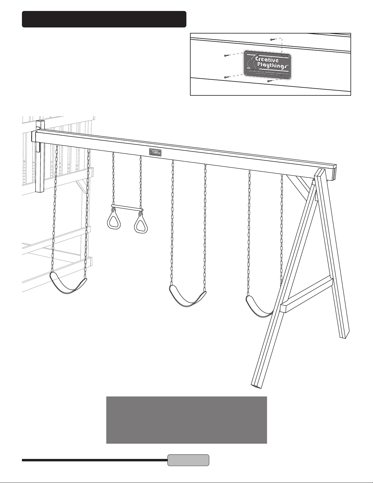
STEP 13 – Nameplate
Federal law requires that the name of the manufacturer be
permanently fastened to the gym, for identication in case
of recall or warranty claim. Your Swing Beam comes with a
nameplate. It is important to fasten the nameplate to the gym.
Use the spacing of the swings to determine placement. Fit
the nameplate at the center of the swing spacing. Use the
included #6 x 1/2" pan head screws to attach the name plate
to the Swing Beam.
IMPORTANT: When installing a Swing Beam to
a Norfolk or Manchester gym, do not install the
two swing hangers closest to the gym. The area
must be kept clear for tire swing clearance.
Popular Baby Swing manuals by other brands


Chad Valley Baby
Chad Valley Baby Circus Friends 580/9866 manual

Leigh Country
Leigh Country TX 93582 instruction manual

active fun
active fun Skyride TP901 Instructions for assembly maintenance and use

Weltevree
Weltevree Serious Swing product manual

Graco
Graco Lovin' Hug 1760908 owner's manual

cam
cam SONNOLENTO Instructions for use