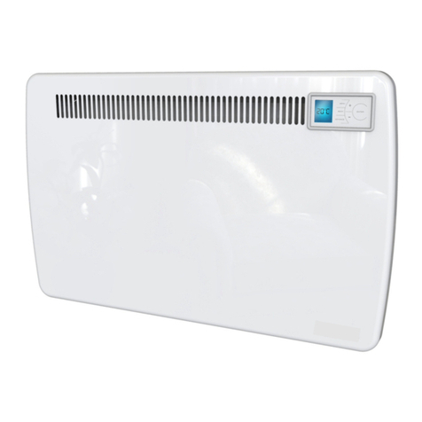
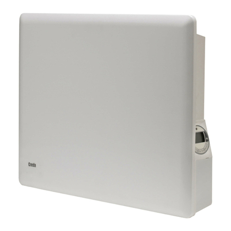
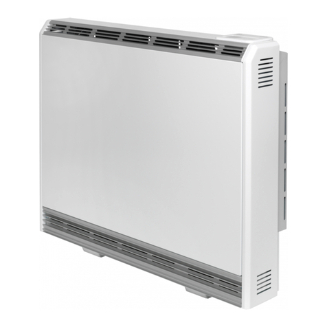
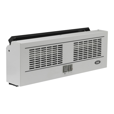
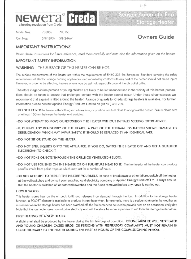
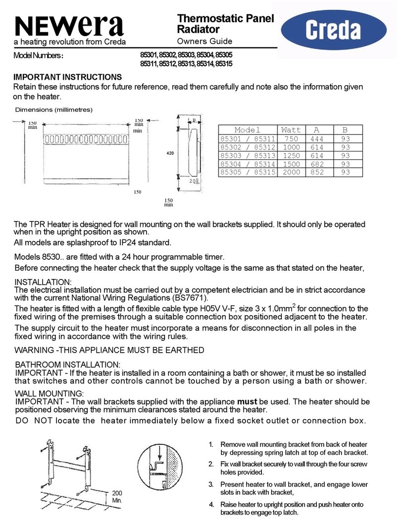
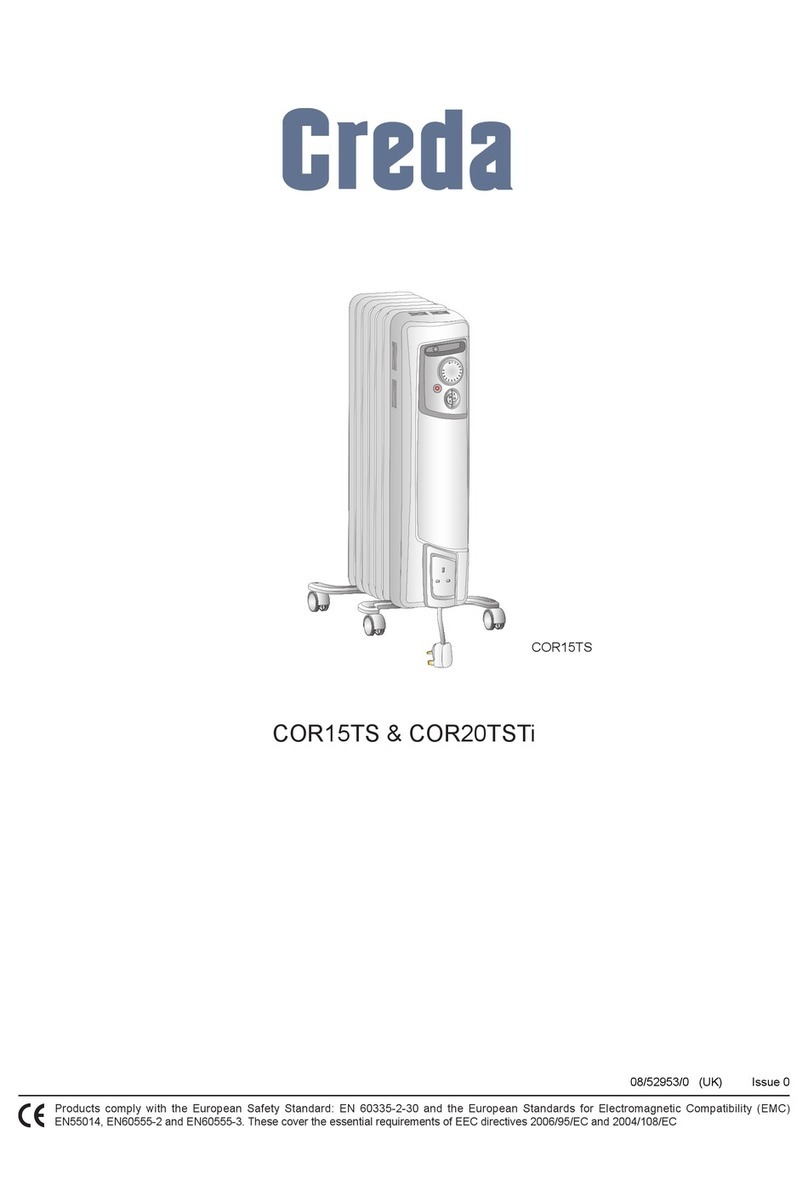
Creda TSF24K User manual

CREDA
Fan
Storage
Heaters
|
stallation
tructions
Models
TSF24K, TSF32K,
TSF42K
AC
only
IMPORTANT
INSTRUCTIONS:
RETAIN
FOR
FUTURE
REFERENCE.
C
Conditions
under
which
despatched
These
instructions
should
be
read
carefully
and
retained
for
future
reference.
Note
also
the
infor-
mation
given
on
the
appliance.
1.
THIS
HEATER
IS
VERY
HEAVY,
BEFORE
INSTALLING
ENSURE
THAT
THE
SUPPORTING
SURFACE
IS
STRONG
ENOUGH
TO
SUPPORT
THE
WEIGHT
OF
THE
HEATER
(SEE
BELOW
“INSTALLED
WEIGHTS“).
IN
ORDER
TO
MAINTAIN
STABILITY
AND
TO
ENSURE
ITS
FUTU-
RE
SAFETY
IN
USE,
IT
IS
ESSENTIAL
THAT
IT
IS
SECURED
TO
A
SOUND
WALL
BY
MEANS
OF
THE
FIXING
SUPPLIED.
IRREGULAR
SURFACES
SUCH
AS
MAY
RESULT
FROM
CAR-
PETS
OR
TILED
SURROUNDS
PARTIALLY
PROTRUDING
UNDER
THE
HEATER
SHOULD
BE
AVOIDED.
IMPORTANT:
ACCESSORY
FEET
ACCESSORY
FEET
ARE
AVAILABLE
TO
FIT
THESE
HEATERS,
AND
SHOULD
BE
USED
WHERE
THE
HEATER
WILL
STAND
ON
THICK
PILE
CARPETS
OR
IN
A
SITUATION
WHERE
OTHERWISE
THE
OUTLET
GRILLE
MAY
BE
OBSTRUCTED.
Installed
Weights
TSF24K
137
kg
TSF32K
.
176
kg
TSF42K
215
kg
2.
All
installations
must
be
supervised
by
a
qualified
electrician.
Installations
and
wiring
must
be
con-
form
to
the
current
IEE
regulations
(UK),
local
or
appropriate
regulations
(other
countries).
PLEASE
NOTE:
THESE
HEATERS
MUST
NOT
BE
CONNECTED
TO
A
30
AMP
RING
CIR-
CUIT.
3.
For
assembly
of
the
heater
the
following
tool
is
required:
Screwdriver
Torx
20
4.
The
minimum
clearances
given
below
must
be
strictly
adhered
to.
DO
NOT
POSITION
THE
HEATERS
UNDER
WINDOWS
WHERE
CURTAINS
MAY
CONTACT
THE
HEATER.
BELOW
SHELF,
OVERHANG:
PARTLY
CONCEALED
BY
Minimum
clearances
of
100
mm
FASCIA
PANEL.
above
and
to
both
sides
of
the
NB
air
ducts
qa
and
@
must
be
heater
must
be
maintained.
NE
maintained.
The
heater
set
and
bricks
are
supplied
separately.
The
heater
set
is
mounted
on
a
wooden
pallet
for
transit
and
consists
of
the
following:
1.
Heater
case
2.
Heating
element
set
containing:
elements
accessory
bag
with
wall
fixing,
charge
control
knob,
wall
bracket
screws
3.
3
Wall
spacer
brackets:
packed
on
top
of
heater
case
CAREFULLY
UNPACK
HEATER
SET
AND
CONFIRM
THAT
PARTS
ARE
COMPLETE
BEFORE
REMOVING
PACKAGING
FROM
SITE.
Bricks
are
supplied
in
boxes
of
3,
marked
328
600.
MODEL
TSF24K
|
TSF32K
TSF42K
BRICKS
SUPPLIED
6
Packs
|
8
Packs
10
Packs
Rating
label
TLIN/EARTH
240V/50Hz
IL/N/EARTH
240V/50Hz
|
TSF
32K
:
7
h
|
Lo;
AW
[1500w
|
Typ:
S30
E
4571
W
|
A
15W
&
|176
kg
Made
in
Germany
32
kWh
|
E-Nr.:
46/2548
FD:
A
weight
)
charge
acceptance
XK
control
part
Ab
auxiliary
heating
a
fan

Unit
assembly
1.Take
the
heater
out
of
its
packaging.
Dispose
of
the
packing
material
in
an
appropriate
way.
Screw
the
two
side
wall
contact
strips
onto
the
back
panel
of
the
heater.
Screw
the
upper
wall
contact
strip
onto
the
two
wall
contact
strips
on
the
sides.
L
KEM
A
He
om]
El
5
Ke
4,2
x
19
42x19
|
B
3.
Note:
The
side
panels
have
keyhole-shaped
cutouts.
For
more
clearness
see
also
step
19
on
page
5.
Push
the
left-hand
and
right-
hand
side
walls
vertically
about
5
mm
upwards
and
then
pull
off
sideways.
Undo
the
fastening
screws
for
the
front
panel.
—
—
Remove
f
Knob
M4x25
M4x25
A
A
2.
Remove
thermostat
knob
on
the
right
side
panel.
Remove
the
fastening
screws
for
the
two
side
walls.
4.
Swing
the
front
panel
forwards
and
remove
it
from
the
upper
edge.
Insert
the
connecting
cables
and
strain-relieve
(see
also
electrical
connection
page
7).
The
connecting
leads
should
be
cut
to
a
suitable
length
so
that
they
cannot
come
into
contact
with
any
hot
surfaces
of
the
heater.
No
loops
of
cable
should
be
left
behind
or
underneath
the
unit.
5.
Stability
The
heater
must
be
fixed
securely
to
a
solid
wall
to
prevent
movement.
A
screw
with
wall
plug
is
provided
in
the
accessory
pack
to
secure
the
heater.
The
assembled
heater
must
be
able
to
resist
a
horizontal
pull
of
at
least
200N
on
its
upper
edge
without
toppling
or
shifting.
If
the
required
stability
cannot
be
achieved
with
the
supplied
accesso-
ries,
e.g.
in
the
case
of
light-construction
walls,
the
installer
must
select
a
suitable
wall
fixing
method.
|
Core
space
=
cover
D
SX
6.
Remove
core
space
cover.
For
this
purpose,
unscrew
the
middle
fastening
screw,
swing
the
core
space
cover
out
slightly
on
the
right-hand
side
and
pull
it
to
the
right.
Lay
the
cover
down
in
such
a
way
as
not
to
damage
the
thermal
insulation.

7.
Remove
the
transport
protection
(folded
cardboard).
side.
Element
slots
must
always
face
upwards.
8.
Put
in
the
lower
row
of
storage
bricks.
Begin
at
the
right-hand
9.
After
putting
in
the
lower
row
of
bricks,
install
the
first
heating
element.
ment.
10.
Put
in
the
second
and
third
rows
of
bricks.
Install
second
ele-
switch
space
outlet
space
11.
After
putting
in
the
fourth
row
of
bricks,
the
third
element
must
be
installed.
Then
slide
the
fifth
row
of
bricks
sideways
under
the
air
outlet
space
and
the
switching
space.
third
element.
12.
Put
in
the
last
row
of
bricks
(6
rows
of
bricks
in
all).
Clean
the
ISERIES
SSDS
SCR
EEN
NOREEN
RETORTED

13.
Refit
core
space
cover.
Left-hand
side:
The
lip
at
the
top
of
the
core
space
cover
must
lie
on
the
left-hand
partition.
The
side
edge
of
the
core
space
cover
must
be
pushed
behind
the
lip
of
the
left-hand
partition.
Right-hand
side:
Insert
side
flange
of
the
core
space
cover
between
the
thermal
insulati-
on
and
the
partition,
paying
attention
to
the
guide
slots.
Tightly
press
the
core
space
cover
and
screw
it
tightly
to
the
right-hand
partition.
14.
Connect
the
element
tails
to
the
cable
harness.
For
this
purpose,
place
the
numbered
connecting
cables
on
the
terminal
ends
of
the
elements.
The
partition
is
also
marked
with
the
corresponding
numbers.
Fasten
loose
cables
to
the
cable
harness
to
oavoid
contact
to
the
hot
ends
of
the
heating
elements.
Electrical
connection
15.
NOTE:
Two
supplies
are
taken
into
the
heater,
an
off-peak
sup-
ply
to
the
heating
element
circuit
and
a
separate
on-peak
supply
to
the
fan
circuit
(see
wiring
diagram).
Refer
to
rating
label
on
front
of
heater
case
for
the
loading
of
heater
and
fan
circuits
on
the
appli-
ance
supplied.
Introduce
mains
supply
cables
through
the
cable
clamps
in
the
back
panel,
to
the
terminal
area,
and
connect
in
accordance
with
the
terminal
markings
and
wiring
diagrams.
Heat
resisting
cable
must
be
used.
Ensure
that
cable
is
clamped
so
that
there
is
no
excess
cable
in
the
terminal
area.
CHECK
ALL
ELEMENT
AND
SUPPLY
CONNECTIONS
FOR
TIGHTNESS.
On
no
account
should
any
surplus
cable
be
pushed
inside
or
behind
the
heater.
The
appliance
must
be
earthed.
Special
instructions:
3
phase
supply
The
heater
is
factory
supplied
for
connection
to
a
single
phase
240
volt
supply.
The
heater
may
alternatively
be
connected
to
a3
phase,
415
volt
supply
by
removal
of
bus-bars,
as
shown
on
the
wiring
diagram.

Completion
of
heater
assembly
16.
Insert
the
front
panel
into
the
folded
edge
on
the
cover,
raising
the
cover
slightly
in
doing
so.
fi
‘a
Eis
i
|
ag
ba
|
|
|
|
7
7
|
k
myy
SV
E
i
17.
Screw
the
front
panel
tightly
(screw
B).
DO
NOT
OVERTIGH-
TEN
THE
SCREWS.
18.
Before
fitting
the
right-hand
side
panel
knock
out
the
plastic
bungs
which
blank
off
the
charge
control
knob
aperture.
19.
The
side
panels
have
keyhole-shaped
cutouts.
Push
the
side
panels
over
the
screws
and
push
downwards.
M4x25
M4x25
A
A
Charge
control
Switch
fan
on/off
Switch
auxiliary
heating
Identification
plate
Thermostat
20.
Screw
the
side
panels
tightly
(screw
A).
DO
NOT
OVERTIGH-
TEN
THE
SCREWS.
Assembly
is
now
finished.
21.
Fit
the
charge
control
knob
and
room
thermostat
control
knob
over
their
spindles
in
the
right-hand
side
panel.
b

23.
Finally,
disconnect
the
electricity
supply
and
connect
each
sup-
ply
cable
to
a
suitable
double
pole
switch
adjacent
to
the
applian-
ce.
The
heater
is
now
ready
for
operation
and
the
supply
may
be
reinstated.
Important:
Commisioning
heater
—
see
overleaf.
Circuit
diagrams
for
Fan
storage
heaters
Models
TSF24K,
TSF32K,
TSF42K
Resetting
the
thermal
cutout
(when
there
has
been
a
fault):
This
should
only
be
done
by
a
skilled
person
!
~
Isolate
the
storage
heater
from
the
power
supply
—
Remove
the
right-hand
side
panel
~
Allow
the
unit
to
cool
down
sufficiently
~
Press
the
reset
button,
e.g.
using
the
blade
of
a
screwdriver
1.
Integral
room
thermostat
(factory
supplied)
Ai/Z1~
Automatic
charge
control
A2/Z2~
(not
available
in
UK)
E
Earth
L1
Live
L2
L3
LE
Thermostat
controlled
discharge
supply
LH
Auxiliary
heater
supply
M1
Fan
N
Neutral
R1
Heating
elements
R2
R3
R7
Fan
resistor
(TSF42K
only)
R8
Charge
control
resistor
R9
Auxiliary
heater
RTR
Room
temperature
control
STR1,2
Thermal
cutout
(automatic
reset)
TB
Thermal
cutout
TR
Charge
control
thermostat
TRO
Temperature
control,
auxiliary
heater
TRG
Temperature
control,
air
grille
Off
peak
(restricted)
supply
Single
phase
connection
~
Sini
j
1L/N/Earth
240
V~
g
N
Off
peak
(restricted)
supply
Three
phase
connection
3L/N/Earth
415
V~
Pek
N
p
Se
MON
‘oe
4”
N
ZLL3—
L3
2
l=
L2
—
L2
TA
rand
aa
E
®©
pe
-PE
On
peak
(24hour)
supply
240
V~

2.
Wall
mounted
room
thermostat
(optional)
A1i/Z1~
Automatic
charge
control
Off
peak
(restricted)
supply
Off
peak
(restricted)
supply
|
A2/Z2~
(not
available
in
UK)
Single
phase
connection
Three
phase
connection
|
|
i
|
TB[
STR2
[5
|
STRI
|
5
|
IL/N/Earth
240
V~
SL/N/Earth
415
V~
l
E
Earth
A
[a
[2]
a
NGA
|
FE
|
Li
Live
enh
[eN
N
|
L2
5
N
—N
5
N=
N
L3
4
N
4
N
LE
Thermostat
controlled
3k
L3
3
l-
L3
—
L3
discharge
supply
|
2eL2—L
2\-l2—
L2
LH
Auxiliary
heater
supply
l1]
L1
4
U=
Lt
M1
Fan
N
Neutral
"OO
re
PE
Sle)
PES—
"PE
R1
Heating
elements
R2
A1/Zi~
Re
A2/Z2~
R7
Fan
resistor
(TSF42K
only)
R8
Charge
control
resistor
R9
Auxiliary
heate
i
RTR
Room
temperature
control
STR1,2
Thermal
cutou
x
i
(automatic
reset)
On
peak
(24hour)
supply
240
V~
rB
Thermal
cutou
TR
Charge
control
thermostat
RQ
emperature
control,
auxiliary
heater
TRG
Temperature
control,
air
grille
Commissioning
When
all
the
installation
work
is
complete,
test
heater
for
operation.
Note:
During
initial
operation
some
odour
may
be
noticed
due
to
the
newness
of
the
materials
used
in
Heater
manufacture.
This
is
normal
and
will
disappear
after
a
short
period
of
use.
It
is,
however,
advisable
to
keep
the
room
will
ventilated.
It
is
also
recommended
that
the
fan
is
run
to
ensure
that
any
dust
particles
that
have
accumulated
in
the
|
heater
are
ejected.
Clean
the
outlet
grille
and
adjacent
surfaces
after
first
operation.
|
In
cases
where
unauthorised
persons
may
tamper
with
the
control
knobs
it
is
possible
to
remove
the
control
knobs
once
the
controls
have
been
put
to
the
correct
setting,
and
fill
the
openings
with
the
pla-
stic
caps
supplied
(see
stage
18
overleaf).

|
|
|
i
i
459273.66.03
05/03/A
Applied
Energy
Products
Limited
Morley
Way
Telephone
01733
456789
Peterborough
Facsimile
01733
310606
PE2
JJ
1
This manual suits for next models
2
Table of contents
Other Creda Heater manuals

Creda
Creda CSS3 User manual

Creda
Creda TSF24K User manual

Creda
Creda CDF2N User manual

Creda
Creda NEWERA 85301 User manual

Creda
Creda Newera 79348S User manual

Creda
Creda CEP 500E User manual

Creda
Creda Newera TSR12AW User manual

Creda
Creda CQH070 User manual

Creda
Creda COR15TS User manual

Creda
Creda TSF24K User manual

Creda
Creda TPRIII050E User manual

Creda
Creda Duo300i User manual

Creda
Creda Arezzo ARE050 Instruction Manual

Creda
Creda Eco-Response ER300 User manual

Creda
Creda Newera TSR18CW User manual

Creda
Creda CLSTH050 Instruction Manual
Creda
Creda CPH05T User manual

Creda
Creda NewEra 70305S User manual

Creda
Creda CSQ15 User manual
Creda
Creda TSRE050 User manual