Creda CDF2N User manual

ContactDetails
Pleasenotethatsomeofthecontactdetailson
thisPDFdocumentmaynotbecurrent.
Pleaseusethefollowingdetailsifyouneedto
contactus:
Telephone:08448793588
Email:[email protected]
TheHelpCentresectionofthiswebsitealsofeaturesawiderange
ofinformationwhichmaybeofusetoyouandisavailable24
hoursaday.Itincludes:
•Operatingandinstallationinstructionsdownloads
•Requestarepair
•Wheretobuyourproducts
•Literaturedownloads
•Heatingrequirementcalculator
www.credaheating.co.uk/help‐centre
A division of GDC Group Ltd
Millbrook House Grange Drive Hedge End Southampton SO30 2DF
www.credaheating.co.uk
Re
g
istered No: 1313016 En
g
land
VAT GB 287 1315 50004
EEE Producer Registration Number –
WEE/GE0057TS
Paper from sustainable sources

Downflow Fan Heater
Model : CDF2N
Installation and Operating Instructions
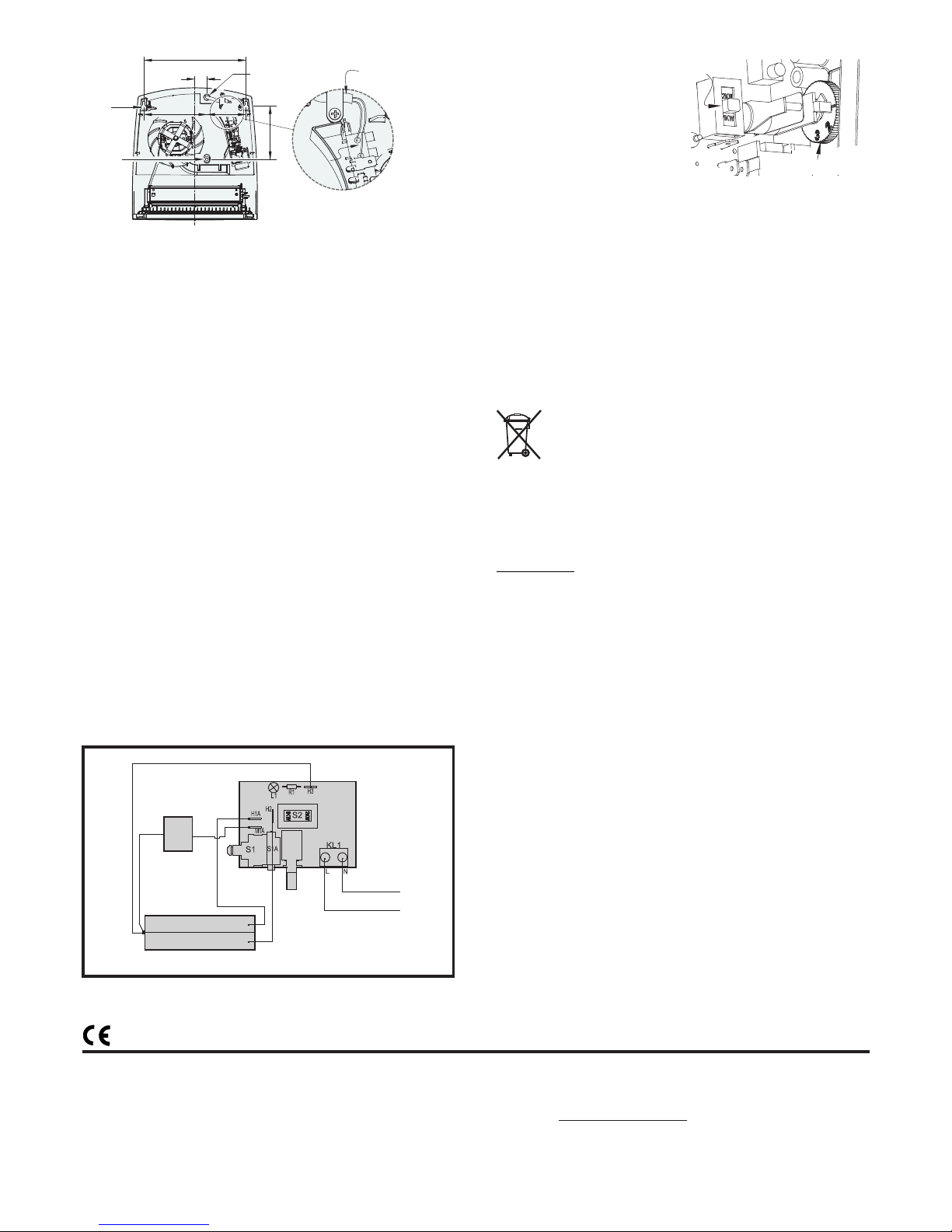
Dimensions
(millimetres)
Model Specification
CDF2N (High level) 1 or 2kW + adjustable thermostat (internal by installer)
Fig. 1
(IPX2)
Important Safety Advice
WARNING - DO NOT USE THIS HEATER IN THE IMMEDIATE
SURROUNDINGS OF ABATH, ASHOWER OR ASWIMMING POOL.
DO NOT COVER THE APPLIANCE or place material or garments
on it, or obstruct the air circulation around this appliance,
for example with curtains or furniture, as this could cause
overheating and a fire risk.
DO NOT PLACE AEROSOLS OR OTHER CONTAINERS
SUSCEPTIBLE TO HEAT IN THE DIRECT AIRFLOW FROM THE
UNIT.
THIS HEATER MUST NOT BE LOCATED IMMEDIATELYBELOW A
FIXED SOCKET OUTLET.
WARNING – DISCONNECT THE HEATER FROM THE ELECTRICITY
SUPPLYBEFORE UNDERTAKING SERVICE OR REPAIR.
WARNING – If the appliance is fitted in a bathroom, a cable
outlet will be necessary with the supply to the unit controlled
by a double pole switch. The switch if inside the bathroom
should be pull cord operated and if outside should be
adjacent to the entrance door. The appliance must be
mounted so that no part of it can be touched by any person
using bath or shower.
THIS HEATER MUST NOT BE OPERATED WITHOUT THE COVER
CORRECTLYIN POSITION, AS THIS WILL TRIP THE THERMAL
FUSELINK.
General
The heater has a loading of 2kW. It is designed for permanent wall
mounting and is suitable for operation on A.C. electricity supply having
the same voltage as shown on the rating label.
The heater is fitted with an internally mounted selector switch which on
installation of the heater allows a choice of 1kW or 2kW output to suit the
dimensions of the room to be heated.
In rooms of less than 9 – 11 cubic m. (350 - 400 cubic ft.) 1kW output
should be selected, otherwise nuisance tripping of the thermal overload
cut-out may occur.
NOTE : THE SWITCH HAS BEEN FACTORYSET FOR 1kW OPERATION.
SUPPLYCABLE IS NOT SUPPLIED WITH THIS APPLIANCE AND IT
SHOULD THEREFORE BE INSTALLED BY ACOMPETENT ELECTRICIAN
IN ACCORDANCE WITH THE LATEST IEE REGULATIONS.
The Controls
The pull cord switch operates the ON/OFF switch inside the heater. An
indicator light will illuminate when the heater is ON and the indicator will
NOT illuminate when the heater is switched off
08/35408/2 Issue 2
IMPORTANT: THESE INSTRUCTIONS SHOULD BE READ CAREFULLY AND RETAINED FOR FUTURE REFERENCE
. NOTE: Only a gentle pull is required. DO NOT pull the cord hard
as damage to the sensitive micro-switch inside the heater may
occur.
Adjustable thermostat
The heater is fitted with an adjustable thermostat which has three
different settings:
1 – Low
2 – Medium
3 – High
This gives you an approximate room temperature range of 18ºC - 32ºC
depending on your room size. The heater is preset to the ‘2 – medium’
setting. To adjust the thermostat setting, remove the front cover and adjust
the thermostat dial to the desired setting (see Fig. 3 on page 2).
2kW setting
Once the room has warmed sufficiently the heater will automatically switch
down to 1kW heat output and will continue to heat indefinitely.
1kW setting
You can permanently change the heat setting manually from 2kW to 1kW
by removing the front cover and sliding the selector switch to the 1kW
setting (see Fig. 3 on page 2).
NOTE: The thermostat will NOT switch the heater ON and OFF and performs
as follows:
2kW setting – heater switches down to 1kW and heat and fan output continue.
1kW setting – heat and fan output continue.
The heater will only switch off when abnormal overheating occurs. See
‘Safety’ section below.
Safety
Cut-Out
For your safety, this appliance is fitted with a thermal cut-out. In the event
that the product overheats, the cut-out switches the heater off automatically.
To bring the heater back into operation, remove the cause of overheating,
then turn off the electrical supply to the heater for a few minutes.
When the heater has cooled sufficiently reconnect and switch on the heater.
Fuse Link
A thermal fuse link is provided as an added safety feature. If the fuse link
operates and opens circuit it is the result of abnormal overheating within
the appliance. To ensure the future safe operation of the appliance customer
service should be contacted.
Installation
Before undertaking installation work, ensure the electricity supply is
disconnected from any relevant fixed wiring. Supply cable is not supplied
with this appliance and it should therefore be installed by a competent
electrician in accordance with the IEE wiring regulations.
The supply circuit must be adequate for the input of the appliance and
must be protected with a 13A fuse.
A suitable termination to the fixed wiring of the premises must be provided
adjacent to the final position of the appliance through a double pole
switch having a contact separation of at least 3mm in all poles.
0,1FHLOLQJ0,1VKHOI0,10,1

Installation Procedure
It is essential to observe minimum wall mounting clearances, as per Fig. 1
overleaf.
The appliance should be fitted horizontally, with the cable entry at the top
and grille at the bottom. It must be mounted not less than 1.8 metres above
the floor with a clearance of at least 600mm to any shelf or projecting
surface below the heater and not less than 300mm below the ceiling or
other projecting surface. It must also be not less than 250mm from an
adjacent projecting surface. For most effective heating performance, the
heater should be mounted at the minimum height:
i.e. 1.8 metres above the floor.
Care must be taken to ensure that when in use, the air stream is not
obstructed by a high shelf or cabinet.
The appliance is secured to the wall with three screws, two through keyhole
slots and one through a centrally positioned lower hole to hold the appliance
firmly in position (see Fig. 2).
1. Remove the top cover from the appliance by removing the two
screws securing the top cover and hinging it back.
2. Mark the position of the keyhole slots on the wall and drill and plug
for the two suitable screws.
3. Partially insert the two screws, then hang the appliance on these
screws and mark the position of the lower centrally positioned screw.
4. Remove the appliance and drill and plug for the third screw.
5. Remount the appliance on the wall, ensure that it is horizontal and
fix in position by tightening all three screws.
6. Feed the supply cord or wires through the inlet at the top rear of the
appliance leaving sufficient free length to connect to the terminal
block.
7. Make electrical connections to the terminal block ensuring that the
live connection is made to the terminal marked ‘L’and the neutral
connection to the terminal marked ‘N’ (see Fig. 2 exploded view).
8. Operate the selector switch to provide either 1kW or 2kW output.
9. Replace the top cover and screws.
The appliance is now ready for use and the electricity supply can be
reinstated.
Fig. 2
Cleaning and User Maintenance
WARNING: BEFORE UNDERTAKING CLEANING OR MAINTENANCE
WORK ON THE APPLIANCE IMMEDIATELYDISCONNECT THE
ELECTRICITY SUPPLYBY SWITCHING OFF AT THE ADJACENT
DOUBLE POLE SWITCH.
The outside can be cleaned by wiping it over with a soft damp cloth and
then dried. Do not use abrasive cleaning powders or furniture polish as
this can damage the surface finish.
Recycling
For electrical products sold within the European Community.
At the end of the electrical products useful life it should not be
disposed of with household waste. Please recycle where
facilities exist. Check with your Local Authority or retailer for
recycling advice in your country.
After Sales Service
If this product appears damaged when first received or does not
function correctly contact us by e-mail customer.services
@credaheating.co.uk or ring 0844 879 35 88 and we will be able to
help. For ROI please phone 018424833.
Do Not Return the product in the first instance as this may delay us
providing you with a satisfactory service.
ACCIDENTAL DAMAGE IS NOT COVERED UNDER THE WARRANTY.
Your product is guaranteed for one year from the date of purchase. Within
this period, we undertake to repair this product free of charge provided it
has been installed and operated in accordance with these instructions.
Should you require assistance with this product please go to
www.credaheating.co.uk and click on “Customer Support” or e-mail us
at customer[email protected]
Alternatively ring our contact centre on 0844 879 35 88 (UK only). This is
a Lo-call no. from a BT landline - other providers including mobile
phones may charge you more. For ROI please phone 01 842 4833.
To assist you, we will need the following information: model number and
serial no (these can be found on the product), nature of the fault and date
of purchase. Please retain your receipt as proof of purchase. Your
rights under this guarantee are additional to your statutory rights, which
in turn are not affected by this guarantee.
Controls
The heater is fitted with a pull cord
operated ON/OFF switch, a
thermostat, a cut-out, and a thermal
fuse link.
The heater has an internal
adjustable thermostat which can
be adjusted by installer (i.e. the top
cover has to be removed), see Fig.
3for controls details with cover
removed.
Temp. range 18°C - 32°C.
Fig. 3
WIRING DIAGRAM
CREDA HEATING
MILLBROOK HOUSE
GRANGE DRIVE
HEDGE END
SOUTHAMPTON
SO30 2DF
1000W
1000W
M
95
2 No.
Slots
Keyhole
188
116
22
72
Exploded view of
Terminal Block
Terminal
Block
L
N
Cable entry
Hole for
3rd Screw
L
C
Mains Cable
'Internal' Adjustable
Thermostat Knob
Selector
Switch
L
N
The product complies with the European Safety Standards EN60335-2-30 and the European Standard Electromagnetic Compatibility (EMC)
EN55014, EN60555-2 and EN60555-3. These cover the essential requirements of EEC Directives 2006/95/EC and 2004/108/EC
[c] GDC Group Ltd,
All rights reserved. Material contained in this publication may not be reproduced in whole or in part, without prior permission in writing of GDC Group
Ltd..
TEL: 0844 879 3588
FAX: 0844 879 3583
WEBSITE: www.credaheating.co.uk
ROI: 01 842 4833
Table of contents
Other Creda Heater manuals

Creda
Creda CSQ15 User manual

Creda
Creda TSRE050 User manual

Creda
Creda Duo300i User manual

Creda
Creda Eco-Response ER300 User manual

Creda
Creda PH2TR Manual

Creda
Creda CLR5C User manual

Creda
Creda TSF24K User manual

Creda
Creda Newera 79348S User manual

Creda
Creda CQH070 User manual

Creda
Creda TSF24K User manual

Creda
Creda Newera TSR18CW User manual

Creda
Creda NEWERA 85301 User manual

Creda
Creda Newera 75772001S User manual

Creda
Creda CAR 033 Instruction Manual

Creda
Creda TPRIII050E User manual

Creda
Creda Sunplus CSP2 Installer manual

Creda
Creda CPH05T User manual

Creda
Creda Newera TSR12AW User manual

Creda
Creda CEP050E User manual

Creda
Creda NP Series User manual