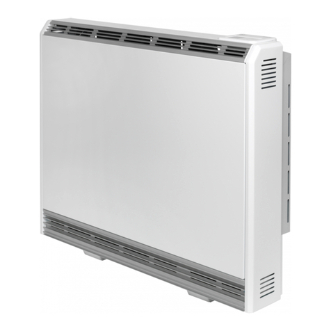
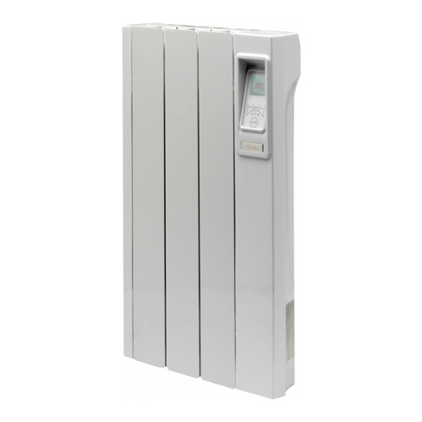
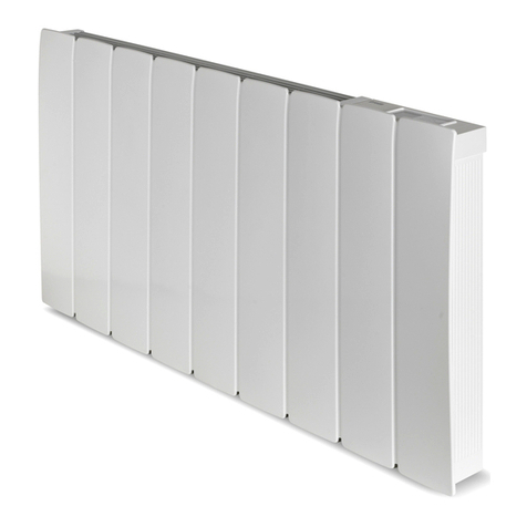
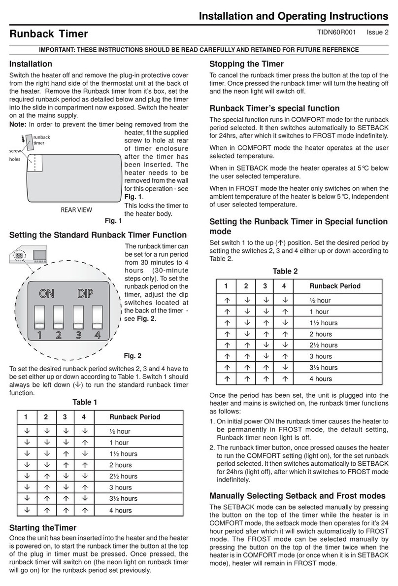
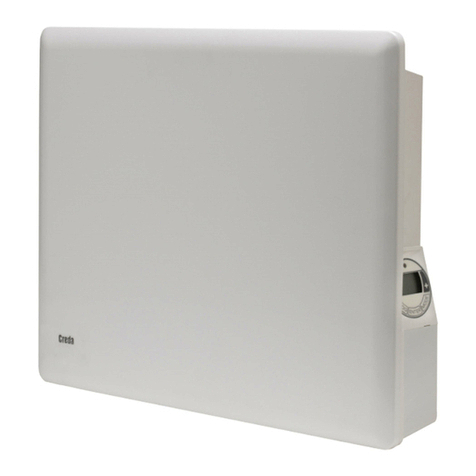
Creda Eco-Response ER300 User manual

- 1 -
Eco-Response Radiator
Models: ER300, ER400 and ER500
Installation Instructions
86576 Issue 1
Dimensions (including clearances diagram)
(millimetres)
Models Specification
ER300 1.3kW / 0.28kW
ER400 1.95kW / 0.34kW
ER500 2.6kW / 0.39kW
THESE INSTRUCTIONS SHOULD BE READ CAREFULLY AND RETAINED FOR FUTURE REFERENCE
NOTE ALSO THE INFORMATION GIVEN ON THE APPLIANCE
These instructions should not be left with the user, as this would invite the dismantling and servicing by unqualified persons.
There is a separate instruction leaflet which should be left with the user explaining how the radiator should be operated.
IMPORTANT SAFETY ADVICE
WARNING - This radiator is VERY HEAVY. In order to maintain stability and to ensure its future safety in use, it is essential
that the radiator is FIXED SOUNDLYTOAWALLand that the feet are mounted on a FIRM, LEVEL SURFACE. Care should
be taken to avoid irregular surfaces, such as may result from tiled surrounds partially protruding under the radiator. It is
important that the following instructions are strictly followed.
WARNING – It is important that the fixing device chosen is appropriate to the wall material to which the radiator is being
fixed. Some modern internal building materials are very low density block and require specialised fixing devices to
provide a safe, secure installation.
WARNING – If during any reassembly of the radiator, a part of the thermal insulation shows damage or deterioration which
may impair safety, it should be replaced with an identical part.
WARNING – This radiator must not be located below a socket outlet.
Suggested Wall Fittings (see page 7 for further information)
Solid brick/block: No. 10 Rawlplug fibre inserts (provided). 5.5mm drill bit. Drill 8mm deeper than rawlplug length.
Plasterboard: If possible locate studding and use No. 10 woodscrews directly into the wood, otherwise M5 intersets.
For other wall types seek specialist advice.
DO NOT COVER OR OBSTRUCT the surfaces of the appliance.
DO NOT POSITION under windows where curtains may contact the radiator (see minimum clearances above).
DO NOT PLACE OBJECTS in contact with the radiator.
Wall,CurtainsorFurniture
Curtains ShelforOverhang
Furniture
orother
obstruction
110mm
150mm
min.
250mm
min.
75mm
min.
75mm
min. A
BC
TOENSURETHISAPPLIANCEIS OPERATING CORRECTLY,ITIS ESSENTIALTOPERFORMTHE CHECKPROCEDUREDETAILEDON
THEBACKPAGEOFTHIS INSTRUCTION.THISMUST BECOMPLETEDBEFORENORMALOPERATIONCOMMENCES.
Model HeightA Width B DepthC
ER300 712mm 600mm 130mm +10mm
ER400 712mm 830mm 130mm +10mm
ER500 712mm 1050mm 130mm +10mm

- 2 -
Energy Retention Cells
Energy retention cells are supplied separately to the radiator in packs of two.
Thereference numberis75-779999.
ER300
8 Cells (4 Packs) ER400
12 Cells (6 Packs) ER500
16 Cells (8 Packs)
Electrical Connection
WARNING– THISAPPLIANCE MUSTBE EARTHED
The installation of this appliance should be carried out by a competent electrician in accordance with I.E.E. Regulations for Electrical
Equipment.
The radiator is fitted with two flexible cables for connection to the fixed wiring of the premises through suitable switched
connection boxes positioned adjacent to the radiator.
Each supply circuit to the radiator must incorporate a means for disconnection in all poles in accordance with the wiring rules.
This radiator is not suitable for connection to a 30A ring circuit.
IMPORTANT
The wires in the mains leads are coloured in accordance with the following code:
GREEN & YELLOW: EARTH
BLUE: NEUTRAL
BROWN: LIVE
BLACK (direct acting supply only): CONTROL WIRE

- 3 -
Circuit Diagram

- 4 -
3
INSTALLATION OF THE RADIATOR
Turnthecartonupside downandopenthe cartonfrom
the bottom. Remove the feet from the polystyrene
corner supports, and the plinth and accessories bag from
the polystyrene centre support.
2
Removetheclip containingthe probefrom thebottom
ofthe radiator. See Picture below.
1
(Do not discard the clip or remove probe from clip).
3
Fitthe feet to theradiator by engagingthe flanges on
the top of the foot with the slots in the base of the
radiator 1. Push the foot towards the back of the radiator
until it is fully engaged 2.
Clip the probe onto the open side of the adjacent foot.
3
ASSEMBLY
2
2
4
Theradiatorispackedwiththedirectactingmainscable
clippedtotheundersideoftheradiatorensuringitissecure
during transit. The off peak mains cable will be secured with
cableties. Priortoinstallingtheradiator,unclipthedirectacting
mainscable(do notremoveor discardtheseclips).
NOTE: If the off peak mains connection is required to be
made on the right hand side of the radiator, the pre-wired
cable must be passed behind the feet and secured using
the clips on the base of the radiator. For ease of access
thisshould be donewhile the radiator isstill upside down
inthecarton. Similarly whenthedirectactingmains cable
isreadytobeconnected(SeeSection23),iftheconnection
isrequired to be madeon the lefthand side of theradiator
thecablemustberoutedbehindthefeet. DONOTclip the
direct acting mains cable at this stage (See Section 23).
The cable clips are already fitted at the factory to allow
both mains cables to be attached, if required.
1
33

- 5 -
6
Stand the radiator on its feet and against a wall.
Remove the securing screws along the bottom edge
ofthe front panel.
7
Swing bottom of panel slightly away from the rest of
the radiator (Fig. 7A) and lift upwards to unhook the
top edge (Fig. 7B).
6
7A7B
5
Stand the radiator on its feet and remove packaging
by sliding over the top of the radiator. Remove all
additionalinternal protective packaging.
5
8
Ensure the electronic components are not damaged
when removing the panel. Carefully place the panel
to one side. Check that the mains supply cables are not
damaged.
If they are to be replaced only heat resistant cable must be
used(min T85). Referto sections 4,21 and22 forfitting the
off-peakand radiant elementcables.
9
Positionradiatoragainstwall inintendedfinal position,
ensuring it is on a firm base and taking note of the
minimumfixing dimensions (see front page).
If the floor is carpeted it is important that the feet are
positioned firmly and securely. The feet may rest on
topofthecarpet, however carpetgrippershouldbe removed
around the feet so that the radiator rests in a level position.
10
7D
Carefully disconnect the
radiant element connector
fromthefront panel(Fig. 7c).
(Seelabelonbottomofheater
andgraphic 7Dbelow).
7C

- 6 -
11
Thefollowingmustbeappliedbeforefixing theradiator
to the wall:
NO SKIRTING BOARD / SKIRTING BOARD NO
TALLER THAN 100MM
11AThe radiator is to be mounted as shown in Fig. 11A,
withthewallspacer bracketinitsstandard orientation.
11BMark the position of the two mounting slots with the
radiator pushed tight against the wall Fig. 11B.
11A
11B
11C
WALL MOUNTING
Use the 10mm spacers provided (4 x 10mm) between
the rear of the radiator and the wall. DO NOT use the
30mm spacers where there are no skirting boards or
they are no taller than 100mm.
11DPlace one 10mm spacer to the inside and another
10mm spacer to the outside of the location hole on
the back panel Fig. 11D(see Fig 11Afor wall spacer
bracketorientation).
11E/FCarefully guide the radiator towards the drilled hole
and screw part way to the wall Fig. 11E& 11F.
11D11E
11F11G
NOTE: UNDER NO CIRCUMSTANCES SHOULD THESE
SCREWS BE REMOVED WITHOUT FIRST REMOVING
ALLENERGYRETENTIONCELLSFROM THE RADIATOR
11CDrill holes into the wall toward the bottom of the
markedslots, as shown in Fig. 11C,following closely
the guidelines opposite.
11GOnce both sides have been successfully positioned
screw the radiator flush to the wall Fig. 11G.
Donot fully tightenthese screws until the core has been
loaded into the radiator as some settling of the radiator
may occur.
IMPORTANT:UNDER NO CIRCUMSTANCES SHOULD
THESE SCREWS BE REMOVED WITHOUT FIRST
REMOVINGALL ENERGY RETENTION CELLS FROM
THERADIATOR
DONOTUSE30MMSPACERONINSIDEOFRADIATOR.
USE ONLY EXTERNALLY - SEE FIG. 12.

- 7 -
12BPlace the 30mm spacer to the outside of the radiator
and the 10mm to the inside Fig. 12B. Drill the holes
asdetailed inSection 11.Carefully guidethe radiator
towardsthe drilledhole. When inposition screw part
way to the wall to secure the radiator as in Section
11, remembering not to fully tighten the screws.
12B
SKIRTING BOARD TALLER THAN 100MM
Use the 10mm and 30mm spacers provided (2 x
10mm and 2 x 30mm)
12A
12
12AIf theskirting board istaller than 100mm,the radiator
is to be mounted as shown in fig 12A. Remove the
wall mounting bracket and reassemble in the
alternative orientation to give a greater spacing
distance from the wall.
IMPORTANT: UNDER NO
CIRCUMSTANCES SHOULD
THESESCREWSBEREMOVED
WITHOUT FIRST REMOVING
ALL ENERGY RETENTION
CELLSFROM THE RADIATOR
Solid brick/High density block walls
Thesemust bedrilledand pluggedwith theRawlplug No.10
sizefibre inserts provided. Thecorrect size of drill(5.5mm)
should be used and the hole should be drilled to a depth of
8mm greater than the length of the Rawlplug so that the
fixing is made below the plaster layer.
Low density block walls
A special fixing, such as Unifix LB70 should be employed,
followingclosely the manufacturer’s instructions.
Panelled internal walls
If possible, locate the studding and use No. 10 size
woodscrews. Whereit isnot possible tolocate thestudding
use type M5 Rawlplug INTERSETS on securely fastened
plasterboard panelling. For other wall materials the wall
panelmanufacturershouldbeconsultedfordetailsofsuitable
wallfixing devices.

- 8 -
13
Removethe innerfront panelby removingthe screws
along its top edge Fig. 13A. Carefully lift the bottom
ofthe frontinner panelout ofthe retaining flangeat thebase
ofthe radiator,Fig. 13B,and remove theinternal packaging,
Fig.13C, taking care notto damage theinsulation attached.
13A
14
Lift out the elements from the base insulation and
rotateforwards.
DONOT DISCONNECT THE TERMINALS
14
13B
13c
15
Carefullyfitthe bottomrow ofthe backlayerof energy
retention cells, placing the two bottom end cells in
position first with the flat side toward the back. Fit the
top row of cells also with the flat side toward the back.
15A15B

- 9 -
16
Refitthe elements bycarefully feeding the tailsdown
through the hole in the base insulation, ensuring the
tab is pointing forward. Fit the front layer of cells with the
flatside toward the frontof the radiator. Ensurethat the tab
on the element is captured below the bottom row of cells
and that the element is vertical.
16A16C
17
Replace the inner front complete with insulation by
locating its bottom edge behind the front lip of the
chassis and inserting the retaining screws along the top
and both sides.
18
Check that the screws securing the radiator to the
wall have been fully tightened. It is essential that all
screws are replaced to ensure earth continuity.
Once installed DO NOT attempt to
reposition the radiator without first
unloading the energy retention cells
and obtaining the services of a
competent electrician.
17
16B
19
In its factory default setting, the radiant element will
be allowed to operate for up to 2 hours after the
beginning of the off-peak charge period to maintain a
comfortableroomtemperature ifrequired. After 2hours the
radiant element will be automatically disabled until the end
ofthe off-peakcharge period.
Incircumstances where it will notbe necessary to maintain
a high ambient room temperature between the hours of
typically 12am and 2am (for example a commercial
application), this feature can be disabled by removing the
time delay pin on the power enable board (see Fig. 19B),
whichwill automaticallyswitch the radiantelement offat the
beginningofthe off-peakcharge period.
19A
19B
RADIANT ELEMENT OVERRIDE

- 10 -
REASSEMBLY
20
Reconnect the radiant element
connector as shown in Fig 20A.
Hook slots at the bottom of the plinth
over the plinth fixing tabs on the plastic
feet, as shown in Fig. 20B. Slide the
plinth into place as shown in Fig. 20c.
Replacetheouterfront panel byhooking
onto the two location clips on the top
panel Fig. 20D, 20E& 20F. Swing the
bottomof thefront panel gentlytowards
theradiator Fig.20Gandcarefully make
sure any excess cable is fed through
into the base of the radiator Fig. 20H.
When securing the front panel with the
screwsprovided, ensure the right hand
corner is secured first to avoid trapping
the cable.
Cut the mains cables to length. Ensuring the
electricity supply is disconnected, connect the free
end of the mains cable to a suitable double pole switch
adjacent to the radiator – reinstate the electricity supply.
Note – the double pole switch must be in accordance
with the requirements of the wiring rules.
ONNOACCOUNTSHOULDANYSURPLUSCABLEBEPUSHEDINSIDEORBEHINDTHERADIATOR.
CHECKALLELECTRICALCONNECTIONS FORTIGHTNESS.
21 22
20A
20E
20F
20D
20C
20B
Ifthedirectactingmainssupplyconnectionistobemade
on the left hand side of the radiator the pre-wired cable
mustbepassedbehindthefeetandsecuredusingtheclipson
thebase ofthe radiator. Twosetsof clipsare alreadyattached
to the base of the radiator to allow the mains cables to travel
paralleltoeachother,ifrequired. SeealsoSection4andFig.4.
20G20H

- 11 -
IMPORTANT
The wires in the direct acting supply cable are coloured in
accordancewith the following code:
GREEN & YELLOW: EARTH
BLUE:NEUTRAL
BROWN: LIVE
BLACK:CONTROL WIRE
TheBLACK control wire is designedto carry asignal froma
compatibleremoteprogrammingdevice.If,however,aremote
programmer is not being used, the appliance may be
connected to the fixed wiring of the premises simply by
cutting back the BLACK control wire, ensuring that it
terminates within the outer insulating sheath of the supply
cable.
DoNOTconnecttheBLACK(PILOT)SIGNAL WIREtoearth.
When the programmer drives other radiators, connect the
pilot wires together.Any 240V double-insulated cable may
beused to linkpilot wires aroundthe ring main.Alowsignal
current is used. Suitable connections would be either an
additional single core wire marked or colour coded
appropriately or use a 4 core cable throughout the radiator
ring. Asa mainsconductor, thepilot wireshould be isolated
in accordance with the IEE regulations.
For further details of connection to programming devices,
pleaserefer to therelevant programmer instructions.
ELECTRICAL CONNECTION
REPLACING MAINS WIRE ON DIRECT ACTING SUPPLY CIRCUIT
HEAT RESISTING CABLE MUST BEUSED (MIN. T85)
Followthe procedureto removethe outerfront.
Removethe PCBBracket fromthe bottomof theouter front.
Removethe wirefrom the connectorblock andearth screw.
Usinga pairofpliers removethe cablegrip fromthe bracket.
The replacement cable will be either 3 core or 4 core.
4 core is only required if a pilot wire is used to control the
radiatorfroman outsidesource.For details ofconnection to
programming devices, please refer to the relevant
ProgrammerInstructions.
Note: Cable outside diameter to be between 6.4 - 7.4 mm
REPLACE CABLE AS FOLLOWS:
Pass new mains cable through hole in side of PCB bracket
connect wires as detailed opposite. Replace cable clamp
ensuring any slack has been pulled back. There will not be
sufficient room for excess cable when the PCB bracket is
replacedonto theouter front.
23
Cleaning
WARNING–ALWAYS DISCONNECT FROM THE
POWERSUPPLYBEFORECLEANING THE RADIATOR.
Donotuse detergents, abrasivecleaningpowder orpolishof
any kind on the body of the radiator.
Allowtheradiatortocool,thenwipe withadryclothtoremove
dustanda dampcloth(notwet) tocleanoff stains.Becareful
not to allow moisture into the radiator.
After Sales Service
Your Radiator is guaranteed for two years from the date of
purchase.Weundertaketorepair orexchangefreeofcharge
within this period, any part found to be defective due to a
manufacturing fault. Your rights under this guarantee are
additional to your statutory rights, which in turn are not
affected by this guarantee. Please retain your receipt as
proofof purchase.

- 12 -
Eco-ResponsehastwoheatoutputmodesComfort (Radiant
Heat) and Background (Retained Heat) . Under normal
operationthetemperaturecontrol displaywillalwaysoperate
theradiant panel, (Comfort).
Note:-Front Panel should befullyinstalled onto radiator
and only Peak supply is switched on, with red bar(s)
showing on the temperature control display, before
starting the check procedure.
1. (i) Adjust the “off-peak” control setting (Background
heat) to position no. 10 as follows; press and hold
down the +button on the temperature control
displayuntil10redbarsareilluminated,continue to
hold the +button for a further 7 seconds and a
singlered bar will flash. Use the+buttontomove
the flashing red bar to the right hand side i.e. the
No.10position(shownbelow).
After 20 seconds the temperature control display
willreturnto theComfort control mode.
(ii) Ensure “Off-Peak” supply is in the Off position.
Unscrew the spur from the wall. Check the
continuity on the storage side of the spur. If the
circuit is closed this will confirm that the “off-peak”
storage circuit (backgroundheat) isoperational.
(iii) If the“off-peak”circuitshows opencircuitandroom
temperatureisbelow25°C, switchoffthe“peak”front
panel electricity supply and check if the “off-peak”
circuit has now closed. If the circuit is still open,
check all electrical connections are secure. Only
then phone the customerhelpline for assistance.
Reconnectspur and switch on radiator.
CHECKPROCEDUREFORINSTALLERSFOLLOWINGINSTALLATION
2. Tocheckthe radiant paneloperation (comfort heat).
(i) Adjust the temperature controldisplay as follows;
press down the +button until 10 red bars are
illuminated (shown below). After 2 minutes the
frontpanelshould nowfeel warm. Thiswill confirm
correctoperation.
(ii) If the front panel does not heat up and room
temperatureisbelow25°C,removefrontpaneland
ensurethereis nodamagetofront panelorradiant
element and that all electrical connections are
secure. Iffront panel isstill not heatingup, phone
the customer help line.
NOTE: If room temperature is above 25°C, radiator
will not operate.
IMPORTANT
Once radiator has been confirmed as fully
operational, use the “Quick Start Guide” to
set up initial customer settings.
Please ensure the “Quick Start Guide” and
the “User Instructions” are left with the
radiator for user information.
THIS CHECK PROCEDURE SHOULD BE CARRIED OUR BYACOMPETENT INSTALLER ONLY. AQUICKSTARTGUIDEAND USER
INSTRUCTIONSARE AVAILABLE FOR END USERS.
Applied Energy Products Limited
Morley Way
Peterborough
England
PE29JJ Telephone: (01733) 456 789
This appliance complies with the European Standards EN 60 335-1, EN 60 335-2-61, EN 61000-3-2,
EN 61000-3-3, EN50366, EN 55014-1 and EN55014-2 for Safety & Electromagnetic Compatibility.
These standards cover the requirement of the EMC Directives 89/336 & 73/23
This manual suits for next models
2
Table of contents
Other Creda Heater manuals

Creda
Creda Newera TSR18CW User manual

Creda
Creda CSS3 User manual

Creda
Creda CQH070 User manual

Creda
Creda TSRE050 User manual

Creda
Creda TSF24K User manual
Creda
Creda CPH05T User manual

Creda
Creda CDF2N User manual

Creda
Creda NP Series User manual

Creda
Creda Newera 75772001S User manual

Creda
Creda NEWERA 85301 User manual

Creda
Creda Newera TSR12AW User manual

Creda
Creda 79341S User manual

Creda
Creda PH2TR Manual

Creda
Creda COR15TS User manual

Creda
Creda TSF24K User manual

Creda
Creda CLSTH050 Instruction Manual
Creda
Creda TSF24K User manual

Creda
Creda CSQ15 User manual

Creda
Creda Duo300i User manual

Creda
Creda Newera 79348S User manual