manuals.online logo
Brands
  1. Home
  2. •
  3. Brands
  4. •
  5. Cree
  6. •
  7. Outdoor Light
  8. •
  9. Cree OSQ HO Series User manual

Cree OSQ HO Series User manual

OSQ HO Series
LED Area Light
Transportation Mount
1 of 3 LPN00597X0001A0_A
INSTALLATION INSTRUCTIONS
INSTRUCTIONS D’INSTALLATION
IMPORTANT SAFEGUARDS
When using electrical equipment, basic safety precautions should
always be followed including the following:
READ AND FOLLOW ALL SAFETY
INSTRUCTIONS
1. DANGER- Risk of shock- Disconnect power before installation.
DANGER – Risque de choc – Couper l’alimentation avant
l’installation.
2. This luminaire must be installed in accordance with the NEC or
your local electrical code. If you are not familiar with these codes
and requirements, consult a qualied electrician.
Ce produit doit être installé conformément à NEC ou votre code
électrique local. Si vous n’êtes pas familier avec ces codes et ces
exigences, veuillez contacter un électricien qualié.
SAVE THESE INSTRUCTIONS FOR
FUTURE REFERENCE
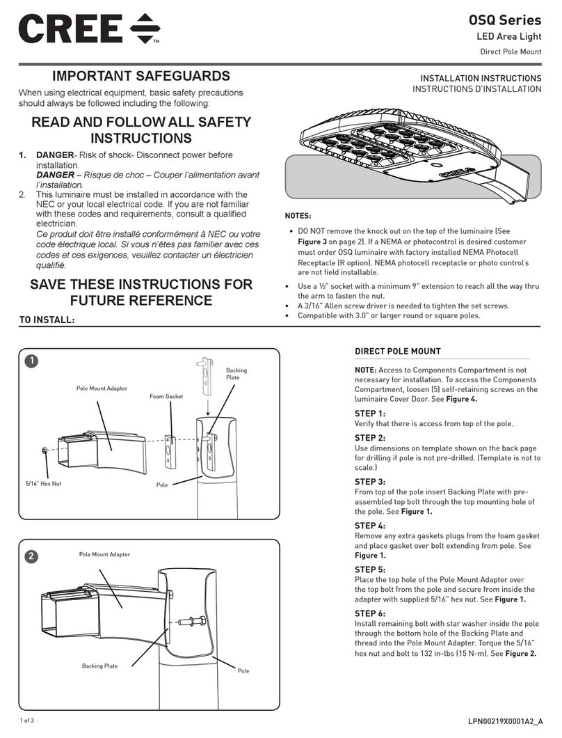
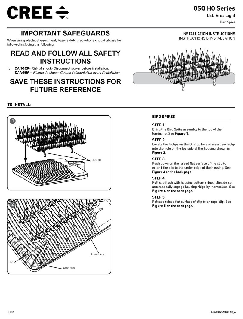
DIRECT MOUNT
STEP 1:
Install grommet into rear mounting bracket. Orient
grommet as shown in Figure 1
STEP 2:
Route power cord from luminaire through grommet in
rear mounting bracket. See Figure 1.
STEP 3:
Slide the rear mounting bracket into the luminaire
housing. See Figure 1.
STEP 4:
Secure rear mounting bracket using (2) 3/8-16 hex
head bolts. Torque bolts to 240 in-lbs (27 N-m). See
Figure 1.
STEP 5:
Secure rear mounting bracket using (2) 5/16-24 set
screws. Torque set screws to 120 in-lbs (14 N-m). See
Figure 1.
STEP 6:
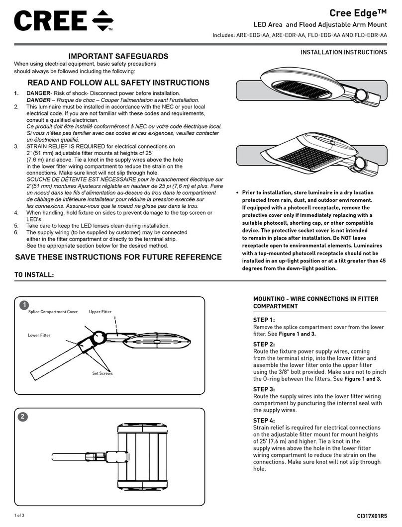
Align front plate with luminaire housing and insert
U-bolt. See Figure 2 and 3.
STEP 7:
Install (2) 1/4-20 nuts with integral lock washer
onto U-bolt. The lock washer should be against the
mounting plate. Torque to 60 in-lbs (7 N-m). See
Figure 2.
STEP 8:
Install (2) 1/4-20 lock nuts and torque to 120 in-lbs
(14 N-m) while holding the nuts installed previously in
Step 7 to prevent rotation. See Figure 2.
TO INSTALL:
1
2
Front Plate
U-Bolt
Nuts
Grommet
Set Screws
Hex Head
Bolts
Rear Mounting Bracket
Lock Nuts
Rear Mounting
Bracket
Grommet
NOTES:
• Before installing, ensure the mounting surface and
securement points are structurally sound and capable of
supporting the weight of the luminaire.
• DO NOT lift the luminaire by the cord.
2 of 3 LPN00597X0001A0_A
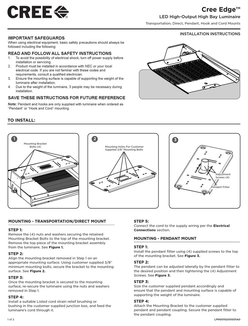
STEP 9:
Place (4) 3/8-16 carriage bolts into top plate slots. Align the top plate
on an appropriate mounting surface. Using customer supplied 3/8”
stainless steel or coated bolts and washers, secure the bracket to the
mounting surface. See Figure 4 and 5.
STEP 10:
Secure luminaire to top plate using (4) 3/8” washers and (4) 3/8-16
nuts. Torque nuts to 240 in-lbs (27 N-m). See Figure 6.
STEP 11:
Insert luminaire cord into customer supplied junction box with suitable
Listed cord strain relief.
STEP 12:
Connect the cord to the supply wiring per the Electrical Connections
section on the last page.
3
5
U-Bolt Position
Bolt
Locations
4
18.00 in
6.00 in
11.10 in
Mounting Holes for 3/8" Fasteners 6
(4) Washers and Nuts
Top Plate
26.00 in
3 of 3 LPN00597X0001A0_A
www.lighting.cree.com
© 2018 Cree, Inc. All rights reserved. For informational purposes only. Content is subject to change.
See http://lighting.cree.com/warranty for warranty and specifications. Cree®is a registered trademark, and the Cree logo is a
trademark of Cree, Inc. NEMA® is a registered trademark of the National Electrical Manufacturers Association.
ELECTRICAL CONNECTIONS
STEP 1:
Using Listed 90°C minimum rated wire connectors make the following
electrical connections within the pole:
a. For 120/277/347V connect the black fixture lead to the voltage
supply or Hot 1 (for 208/240/480V wiring).
b. For 120/277/347V connect the white fixture lead to the neutral
supply or Hot 2 (for 208/240/480V wiring).
c. Connect the green or green/yellow ground lead to ground.
d. If Dimming is an option; connect the violet dimming positive lead
to the supply dimming positive lead.
e. If Dimming is an option; connect the grey dimming negative lead
to the supply dimming negative lead.
LINE
OR HOT 1
GREEN
LINE-BLACK
GROUND-GREEN
NEUTRAL-WHITE
DIM (-) GREY
DIM (+) VIOLET
NEUTRAL
OR HOT 2
VIOLET
GREY
SUPPLY WIRING
(DIMMING OPTIONAL)
LUMINAIRE
DRV
DRV CRTL
1 2 3 4 5
9123
4
5
6
7
8
8
Luminaire Cover Door
7
FIELD ADJUSTABLE DIMMING - (OPTIONAL)
NOTE: This luminaire may be provided with field
adjustable dimming. If so, luminaires leave the
factory adjusted to the maximum setting specified
when ordered. Visit the product specification sheet
for lumen and power multipliers for each field
adjustable output dim setting..
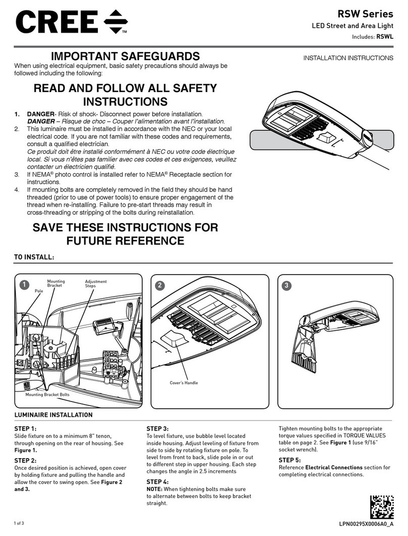
STEP 1:
The Dimming module is located inside the luminaire.
Open the luminaire door cover by loosening the (7)
screws. See Figure 7.
STEP 2:
Establish the desired input power multiplier by
referring to the product dimming spec sheet and turn
the switch to the correlating position
STEP 3:
Adjust the Dimming Module, see Figure 8, to the
selected position and reinstall the cover ensuring no
wires are pinched.

Other Cree Outdoor Light manuals

Cree XSP Series User manual

Cree

Cree XSP Series User manual

Cree OSQ Series User manual

Cree

Cree OSQ Series User manual

Cree Edge Series User manual

Cree

Cree Edge Series User manual

Cree Edge ARE-EDG-AA User manual

Cree

Cree Edge ARE-EDG-AA User manual

Cree RSWL User manual

Cree

Cree RSWL User manual

Cree XSP Series User manual

Cree

Cree XSP Series User manual

Cree VG Series User manual

Cree

Cree VG Series User manual

Cree EDGE XPS Transportation Series User manual

Cree

Cree EDGE XPS Transportation Series User manual

Cree Edge ARE-EDR-R4 User manual

Cree

Cree Edge ARE-EDR-R4 User manual

Cree NTW Series User manual

Cree

Cree NTW Series User manual

Cree OSQ HO Series User manual

Cree

Cree OSQ HO Series User manual

Cree LEDway Series User manual

Cree

Cree LEDway Series User manual

Cree NTW Series User manual

Cree

Cree NTW Series User manual

Cree XSP Series User manual

Cree

Cree XSP Series User manual

Cree C-Lite C-WP-A-TR Series User manual

Cree

Cree C-Lite C-WP-A-TR Series User manual

Cree NTA Series User manual

Cree

Cree NTA Series User manual

Popular Outdoor Light manuals by other brands

Quoizel BUK8405MBK installation guide

Quoizel

Quoizel BUK8405MBK installation guide

Cameo F2 D IP user manual

Cameo

Cameo F2 D IP user manual

Renkforce 1361116 operating instructions

Renkforce

Renkforce 1361116 operating instructions

LIGMAN VANCOUVER 15 installation manual

LIGMAN

LIGMAN VANCOUVER 15 installation manual

Kogan SMARTERHOME RGB user guide

Kogan

Kogan SMARTERHOME RGB user guide

Endon Grant YG-7501 instruction manual

Endon

Endon Grant YG-7501 instruction manual

&Tradition JOURNEY SHY2 User instructions

&Tradition

&Tradition JOURNEY SHY2 User instructions

Current Evolve EWAS A Series installation guide

Current

Current Evolve EWAS A Series installation guide

Lumatek LK2S0 quick start guide

Lumatek

Lumatek LK2S0 quick start guide

Essertec essertop Assembly instruction

Essertec

Essertec essertop Assembly instruction

PUK GRAZER Assembly and operating instructions

PUK

PUK GRAZER Assembly and operating instructions

BEGA 84 121 Instructions for use

BEGA

BEGA 84 121 Instructions for use

Thorn CIVITEQ installation instructions

Thorn

Thorn CIVITEQ installation instructions

STEINEL L 676 LED installation instructions

STEINEL

STEINEL L 676 LED installation instructions

Kenroy Home HARBOUR 33155 Use and care guide

Kenroy Home

Kenroy Home HARBOUR 33155 Use and care guide

GUBI Seine Assembly instructions

GUBI

GUBI Seine Assembly instructions

ADEO Services OS2602 WHITE instruction manual

ADEO Services

ADEO Services OS2602 WHITE instruction manual

LIGMAN LIGHTWAVE 3 installation manual

LIGMAN

LIGMAN LIGHTWAVE 3 installation manual

manuals.online logo
manuals.online logoBrands
  • About & Mission
  • Contact us
  • Privacy Policy
  • Terms and Conditions

Copyright 2025 Manuals.Online. All Rights Reserved.