manuals.online logo
Brands
  1. Home
  2. •
  3. Brands
  4. •
  5. Cree
  6. •
  7. Outdoor Light
  8. •
  9. Cree LEDway Series User manual

Cree LEDway Series User manual

1 of 3 LPN00207X0001A0
LEDway® Series
High Output LED Street Light
Includes: Single and Double Modules
INSTALLATION INSTRUCTIONS
IMPORTANT SAFEGUARDS
When using electrical equipment, basic safety precautions should always be followed
including the following:
READ AND FOLLOW ALL SAFETY INSTRUCTIONS
1. To avoid the possibility of electrical shock, turn off power supply before installation
or servicing. Installation and servicing should be performed by qualied personnel.
2. When closing cover of xture, be sure all wires are inside housing to avoid pinching
wires.
3. If NEMA photo control is installed refer to NEMA Receptacle section for instructions.
4. Product must be installed in accordance with NEC or your local electrical code.
If you are not familiar with these codes and requirements, consult a qualied
electrician.
5. If mounting bolts are completely removed in the eld they should be hand threaded
(prior to use of power tools) to ensure proper engagement of the thread when
re-installing. Failure to pre-start threads may result in cross-threading or stripping of
the bolts during reinstallation.
SAVE THESE INSTRUCTIONS FOR FUTURE REFERENCE
TO INSTALL:
STANDARD MOUNTING
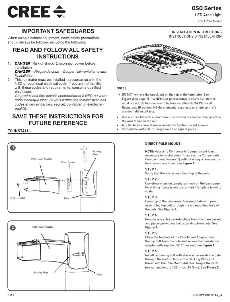
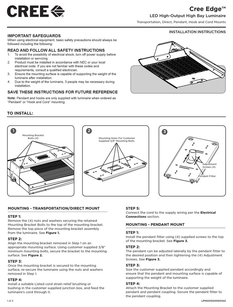
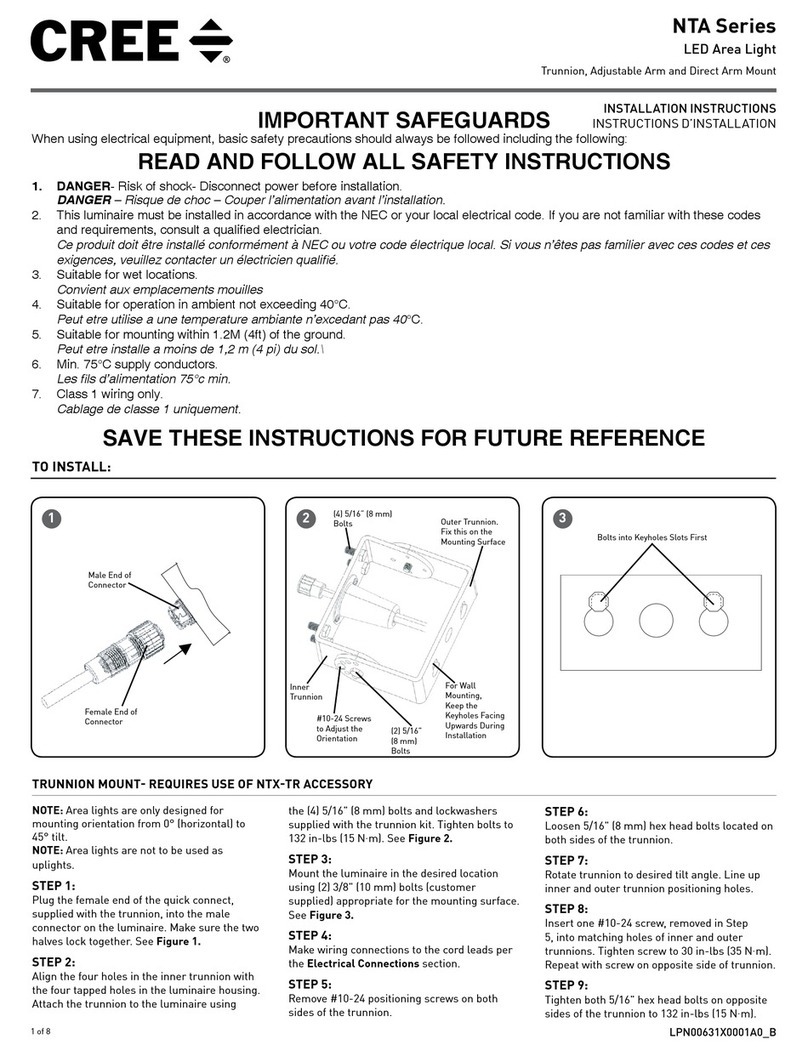
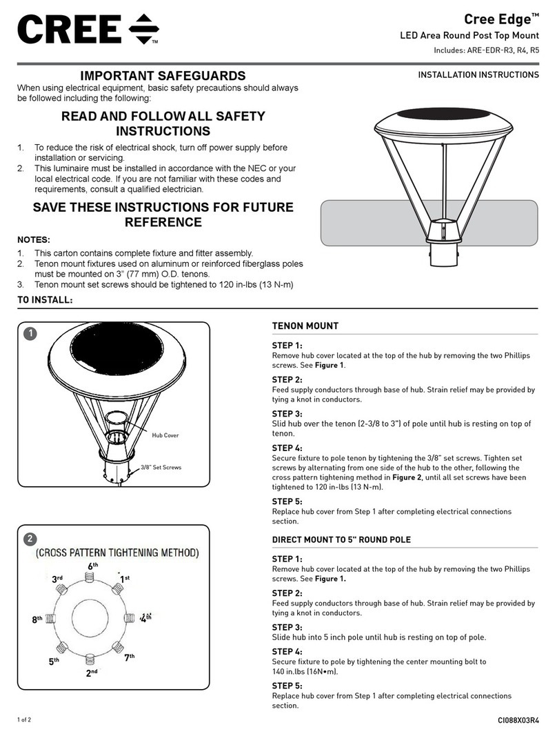
STEP 1:
DO NOT remove splashguard from fixture. If
mounting fixture to 1.25 IP pipe (1.66 O.D.),
there is no need to modify the splashguard. If
mounting fixture onto 2.0 IP pipe (2.38 O.D.),
remove the knockout of the splashguard
thru the rear opening of the fixture while the
fixture is closed. See Figure 2.
STEP 2:
To open cover, hold fixture by heat sink
with the light bars facing down and hinges
facing away. Simultaneously pull latches
and the cover to swing open. Splashguard
may dislodge from fixture, but should be
repositioned once ready to mount. See
Figure 1.
STEP 3:
Slide fixture on to pole through opening on
the rear of housing and through splashguard.
STEP 4:
To level fixture, use bubble level located inside
housing. Adjust leveling of fixture from side
to side. To level from front to back, slide pole
to different step in upper housing. Each step
changes the angle in 2.5° increments. See
Figure 3.
STEP 5:
Once desired position is achieved, tighten
(2) mounting bolts to the appropriate torque
values specified in TABLE 1. See Figure 1 (use
9/16" wrench socket).
IMPORTANT - DO NOT exceed these
torque levels on the mount bolts. Exceeding
recommended torque value resulting in
excessive deformation of mounting bracket
will cause stripping of mount hardware which
could lead to an unsafe mounting condition.
STEP 6:
Reference “Electrical Connections” section
for completing electrical connections.
1
Pipe Size Pipe Position Bolt Torque
Required (in-lbs)
Bolt Torque
Required (N-m)
1.66 in O.D.
+5.0 degrees tilt 400 45
+2.5 degrees tilt 400 45
0 degrees (no tilt) 400 45
-2.5 degrees tilt 700 79
-5.0 degrees tilt 850 96
2.38 in O.D.
+5.0 degrees tilt 300 33
+2.5 degrees tilt 300 33
0 degrees (no tilt) 300 33
-2.5 degrees tilt 300 33
-5.0 degrees tilt 300 33
Heatsink
Mounting Clamp
Bracket
Mounting Bolts (2)
See Table 1
Cover in Open
Position
Pole
Driver
Splashguard
Cover in Open
Position
Terminal Block
TABLE 1
2
3
Fitter Pipe end
Final Stop Boss
2nd Stop Boss
3rd Stop Boss
2 of 3 LPN00207X0001A0
ELECTRICAL CONNECTIONS
PHASE TO NEUTRAL WIRING
STEP 1:
Make the following Electrical Connections:
a. Connect supply ground conductor to green wire position
of the terminal block within the LED Driver Enclosure.
b. Connect supply voltage conductor to black wire position
of the terminal block within the LED Driver Enclosure.
c. Connect supply neutral conductor to the white wire
position of the terminal block within the LED Driver
Enclosure.
STEP 2:
Push excess supply wires into pole.
STEP 3:
Close cover by firmly pushing cover towards fixture, making sure
that no wires are pinched and latches are fully engaged.
STEP 4:
Insulate all electrical connections with wire nuts suitable for at
least 90°C
LINE
OR LINE 1
GREEN
LINE-BLACK
LINE-BLACK
GROUND-GREEN
NEUTRAL-WHITE
COMMON-WHITE
NEUTRAL
OR LINE 2
SUPPLY WIRING
FIXTURE WIRING
LED DRIVER(S)
TERMINAL BLOCK
N
G
L
DRV
A
B
C
D
E
F
G
I
DRV CRTL
1 2 3 4 5
4
NEMA RECEPTACLE (OPTIONAL)
STEP 1:
DO NOT loosen/tighten flat head screws for the NEMA receptacle.
STEP 2:
Rotational adjustment of the photo control is tool-less.
STEP 3:
Engage/install photo control into NEMA receptacle on top of the
fixture.
STEP 4:
Firmly rotate photo-control with its photo-eye approximately in the ‘N’
north direction. Some photo-controls operate best somewhere between
NW and NE.
FIELD ADJUSTABLE DIMMING (OPTIONAL)
NOTE: This luminaire may be provided with field adjustable dimming.
Luminaires leave the factory adjusted to the maximum setting specified
when ordered. Visit www.cree.com/Lighting/Document-Library for
product dimming spec sheet.
STEP 1:
The Dimming module is located inside the luminaire. Open the cover by
loosening the captive D-ring and allow the cover to swing open.
STEP 2:
Establish the desired input power multiplier by referring to the product
dimming spec sheet and turn the switch to the correlating position
STEP 3:
Adjust the Dimming Module, see Figure 4, to the selected position and
close the cover ensuring no wires are pinched.
NOTE: The Utility Option will be limited to the highest setting ordered.
3 of 3 LPN00207X0001A0
www.cree.com/lighting
© 2014 Cree, Inc. All rights reserved. For informational purposes only. Content is subject to change. See
www.cree.com/lighting/products/warranty for warranty and specifications. Cree®, the Cree logo, and
LEDway® are registered trademarks of Cree, Inc.
ELECTRICAL CONNECTIONS
PHASE TO PHASE WIRING
STEP 1:
Make the following Electrical Connections:
a. Connect supply ground conductor to green wire
position of the terminal block within the LED Driver
Enclosure.
b. Connect supply L1 (Hot) conductor to black wire
position of the terminal block within the LED Driver
Enclosure.
c. Connect supply L2 (Hot) conductor to the white
wire position of the terminal block within the LED
Driver Enclosure.
STEP 2:
Push excess supply wires into pole.
STEP 3:
Close cover by firmly pushing cover towards fixture,
making sure that no wires are pinched and latches are fully
engaged.
STEP 4:
Insulate all electrical connections with wire nuts suitable
for at least 90°C
GROUND
LINE-BLACK
GROUND-GREEN
COMMON-WHITE
LINE (L2)
SUPPLY WIRING
FIXTURE WIRING
LED DRIVER(S)
TERMINAL BLOCK
N
G
L
LINE (L1)
208, 240, 480V

Other Cree Outdoor Light manuals

Cree EDGE XPS Transportation Series User manual

Cree

Cree EDGE XPS Transportation Series User manual

Cree XSP Series User manual

Cree

Cree XSP Series User manual

Cree Edge ARE-EDG-AA User manual

Cree

Cree Edge ARE-EDG-AA User manual

Cree RSWL User manual

Cree

Cree RSWL User manual

Cree Edge Series User manual

Cree

Cree Edge Series User manual

Cree NTW Series User manual

Cree

Cree NTW Series User manual

Cree OSQ Series User manual

Cree

Cree OSQ Series User manual

Cree OSQ HO Series User manual

Cree

Cree OSQ HO Series User manual

Cree OSQ HO Series User manual

Cree

Cree OSQ HO Series User manual

Cree NTA Series User manual

Cree

Cree NTA Series User manual

Cree NTW Series User manual

Cree

Cree NTW Series User manual

Cree VG Series User manual

Cree

Cree VG Series User manual

Cree XSP Series User manual

Cree

Cree XSP Series User manual

Cree C-Lite C-WP-A-TR Series User manual

Cree

Cree C-Lite C-WP-A-TR Series User manual

Cree XSP Series User manual

Cree

Cree XSP Series User manual

Cree Edge ARE-EDR-R4 User manual

Cree

Cree Edge ARE-EDR-R4 User manual

Popular Outdoor Light manuals by other brands

Hyundai Lighting Garden Glow installation manual

Hyundai Lighting

Hyundai Lighting Garden Glow installation manual

HEPER LL2031.511-US Installation & maintenance instructions

HEPER

HEPER LL2031.511-US Installation & maintenance instructions

nordlux VEJERS 25091003 Mounting instruction

nordlux

nordlux VEJERS 25091003 Mounting instruction

LIGMAN MV-30002 instruction manual

LIGMAN

LIGMAN MV-30002 instruction manual

Addington Park 31796 quick start guide

Addington Park

Addington Park 31796 quick start guide

LightPro Juno 2 user manual

LightPro

LightPro Juno 2 user manual

Simx Lighting LHT0269 installation instructions

Simx Lighting

Simx Lighting LHT0269 installation instructions

Hess NOVARA SL Installation and operating instructions

Hess

Hess NOVARA SL Installation and operating instructions

Briloner MAL 2763 Mounting instructions

Briloner

Briloner MAL 2763 Mounting instructions

Santa & Cole Urbidermis SLOPE INDUSTRIAL FACILITY manual

Santa & Cole Urbidermis

Santa & Cole Urbidermis SLOPE INDUSTRIAL FACILITY manual

RAB Lighting WP4 Series installation instructions

RAB Lighting

RAB Lighting WP4 Series installation instructions

Faro Barcelona MAYA 1 instructions

Faro Barcelona

Faro Barcelona MAYA 1 instructions

StreamLight SIEGE X USB operating instructions

StreamLight

StreamLight SIEGE X USB operating instructions

Paradise Datacom GL28649 quick start guide

Paradise Datacom

Paradise Datacom GL28649 quick start guide

LED's light 1000434 instruction manual

LED's light

LED's light 1000434 instruction manual

IKEA NAVLINGE G1901 manual

IKEA

IKEA NAVLINGE G1901 manual

Faro Barcelona LE VITA 29691 instructions

Faro Barcelona

Faro Barcelona LE VITA 29691 instructions

Santa & Cole SYLVESTRINA manual

Santa & Cole

Santa & Cole SYLVESTRINA manual

manuals.online logo
manuals.online logoBrands
  • About & Mission
  • Contact us
  • Privacy Policy
  • Terms and Conditions

Copyright 2025 Manuals.Online. All Rights Reserved.