Fuse Replacement
If the amplifier does not power up when the power is turned on, the fuse may need to be
replaced. The fuse holder is located on the rear panel next to the power switch. To replace the
fuse:
1. Disconnect power to the amplifier.
2. Use a flat head screwdriver to push in the fuse holder.
3. While pushing in the fuse holder, turn the screwdriver counterclockwise until the fuse holder
pops out.
4. Remove the fuse from the fuse holder and insert a new fuse.
MODELS REQUIRED FUSE TYPE
AMP-8075
AMP-8150
(US & Canada)
10.0 A, Time lag, 1.25 in. x 0.25 in.,
Ceramic Cartridge, 250 V
AMPI-8075
AMPI-8150
(International/220-240 VAC)
6.3 A, Time Lag, 5 x 20 mm,
Ceramic Cartridge, 250 V
CAUTION: Use the specified type of fuse only. Failure to do so may cause damage to the
amplifier.
NOTE: One spare fuse is included.
5. Insert the fuse holder into the amplifier.
6. Push in the fuse holder with a flat head screwdriver.
7. Push in the fuse holder a little further and turn the screwdriver clockwise until the fuse
holder locks in place.
8. Connect power to the amplifier.
Operate the Device
Apply Power
To turn the amplifier and audio outputs on, move the power switch (located next to the power
connector) to |. To turn the amplifier and audio outputs off, move the power switch to O. This will
also reset the unit.
When power is applied to the device, the PWR LED on the front panel operates with the following
behavior:
• Green - Normal operation
• Amber - Device is booting up
• Amber/Green (Cycling) - No network connection
Adjust the Signal Levels
Each channel has a corresponding input attenuator on the rear panel. Adjustments can be
made here to achieve the desired loudness in each zone. To adjust an input's level, turn the knob
clockwise to increase the signal level or counterclockwise to reduce the signal level.
Monitor Operation
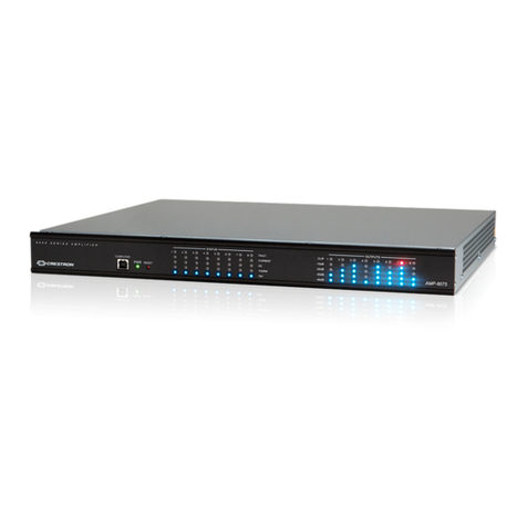
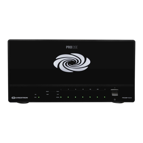
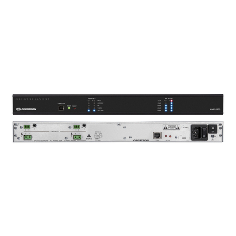
Use the front panel's status indicators and VU level meters to monitor each speaker output.
LEDs in the STATUS section indicate the following for each output:
• Presence of a fault
• An overcurrent condition
• A DC offset condition
• Excessive operating temperature
• 70 volt operation (100 volt operation for AMPI-8075 and AMPI-8150)
LEDs in the VU section indicate each output's signal level and whether a clipping condition is
present.
Reset the Device
Press RESET on the front panel to restart the device.
Connect to Crestron XiO Cloud Service (Optional)
The Crestron XiO Cloud™ service allows supported Crestron devices across an enterprise to
be managed and configured to connect to the service. Use of the service requires a registered
Crestron XiO Cloud account.
NOTE: The device can be disconnected from the service using the Cloud Services tab in the
Crestron Toolbox™ software (Functions > Device Info > Cloud Services). For details, refer to the
Crestron Toolbox help file.
To connect the device to the Crestron XiO Cloud service:
• Access the Crestron XiO Cloud Service at https://portal.crestron.io.
• Register for a Crestron XiO Cloud account at www.crestron.com/xiocloud.
For detailed information about using the Crestron XiO Cloud service, refer to the Crestron XiO
Cloud Service User Guide (Doc. 8124) at www.crestron.com/manuals.
Additional Information
Scan or click the QR code for detailed product information.
AMP-8075 AMPI-8075 AMP-8150 AMPI-8150
Compliance and Legal
Original Instructions: The U.S. English version of this document is the original instructions. All other languages are a translation of the original instructions.
As of the date of manufacture, the product has been tested and found to comply with specifications for CE marking.
This product is Listed to applicable UL® Standards and requirements tested by Underwriters Laboratories Inc.
Ce produit est homologué selon les normes et les exigences UL applicables par Underwriters Laboratories Inc.
Federal Communications Commission (FCC) Compliance Statement
These devices comply with part 15 of the FCC Rules. Operation is subject to the following conditions: (1) This device may not cause harmful interference and (2) this device must accept any
interference received, including interference that may cause undesired operation.
CAUTION: Changes or modifications not expressly approved by the manufacturer responsible for compliance could void the user’s authority to operate the equipment.
NOTE: This equipment has been tested and found to comply with the limits for a Class A digital device, pursuant to part 15 of the FCC Rules. These limits are designed to provide reasonable
protection against harmful interference when the equipment is operated in a commercial environment. This equipment generates, uses, and can radiate radio frequency energy and, if not
installed and used in accordance with the instruction manual, may cause harmful interference to radio communications. Operation of this equipment in a residential area is likely to cause harmful
interference in which case the user will be required to correct the interference at his own expense.
Industry Canada (IC) Compliance Statement
CAN ICES-3 (A)/NMB-3(A)
Rack Mounting Safety Precautions
• Elevated Operating Ambient Temperature: If installed in a closed or multi-unit rack assembly, the operating ambient temperature of the rack environment may be greater than room
ambient temperature. Therefore, consideration should be given to installing the equipment in an environment compatible with the maximum ambient temperature (Tma) specified by the
manufacturer.
• Reduced Airflow: Installation of the equipment in a rack should be such that the amount of airflow required for safe operation of the equipment is not compromised.
• Mechanical Loading: Mounting of the equipment in the rack should be such that a hazardous condition is not achieved due to uneven mechanical loading.
• Circuit Overloading: Consideration should be given to the connection of the equipment to the supply circuit and the effect that overloading of the circuits might have on overcurrent
protection and supply wiring. Appropriate consideration of equipment nameplate ratings should be used when addressing this concern.
• Reliable Earthing: Reliable earthing of rack-mounted equipment should be maintained. Particular attention should be given to supply connections other than direct connections to the branch
circuit (e.g., use of power strips).
Electrical Connection:
“This product must be connected to an earthed mains socket-outlet.”
• Finland: “Laite on liitettävä suojamaadoituskoskettimilla varustettuun pistorasiaan.”
• Norway: “Apparatet må tilkoples jordet stikkontakt.”
• Sweden: “Apparaten skall anslutas till jordat uttag.”
The product warranty can be found at www.crestron.com/warranty.
The specific patents that cover Crestron products are listed at
www.crestron.com/legal/patents.
Certain Crestron products contain open source software. For specific information, please
visit www.crestron.com/opensource.
Crestron, the Crestron logo, Crestron Avia, Crestron Toolbox, and Crestron XiO Cloud are either trademarks or registered trademarks of Crestron Electronics, Inc. in the United States and/
or other countries. Windows is either a trademark or registered trademark of Microsoft Corporation in the United States and/or other countries. UL and the UL logo are either trademarks or
registered trademarks of Underwriters Laboratories, Inc. in the United States and/or other countries. Other trademarks, registered trademarks, and trade names may be used in this document
to refer to either the entities claiming the marks and names or their products. Crestron disclaims any proprietary interest in the marks and names of others. Crestron is not responsible for errors
in typography or photography.
©2019 Crestron Electronics, Inc.
Crestron Electronics, Inc.
15 Volvo Drive, Rockleigh, NJ 07647
Tel: 888.CRESTRON
Fax: 201.767.7576
www.crestron.com
Quick Start - Doc. 7813F
(2053720)
05/31/19
Specifications subject to
change without notice.
