CRH Leviat Halfen DEHA KKT-E User manual

®
HALFEN KKT-E INST_KKT-E 02/23
Assembly Instructions • Montageanleitung • Notice d‘utilisation • Instrukcja montażu
EN HALFEN DEHA
Lifting Anchor System,
Inserts
DE HALFEN DEHA
Kugelkopfanker,
Einbauteile
FR Système à ancres de
levage HALFEN DEHA,
inserts
PL Kotwy transportowe
HALFEN DEHA
z głowicą kulową

2© 2023 HALFEN · INST_KKT-E 02/23 · www.halfen.com
HALFEN KKT-E
EN
Important changes for use in the UK:
The UK is transitioning to its own UK based approval system and, as a result, from January 2023 will no
longer accept CE marking. Leviat already has new UKCA marking in place and from 2023 at the latest, the
UKCA mark will also be applied directly to the lifting systems, as required by the UKCA regulations. The
conformity assessment processes and standards that can be used to demonstrate conformity under UKCA
marking are aligned with those required for CE marking, so there is no difference in performance or testing
requirements.
FR
Changements importants pour l‘utilisation au Royaume-Uni :
Le Royaume-Uni est en train de passer à son propre système d‘approbation basé au Royaume-Uni et, par
conséquent, à partir de janvier 2023, il n‘acceptera plus le marquage CE. Leviat a déjà mis en place le nouveau
marquage UKCA et à partir de 2023 au plus tard, le marquage UKCA sera également appliqué directement sur les
produits de levage, comme l‘exige la réglementation UKCA. Les processus et les normes d‘évaluation de la
conformité, qui peuvent être utilisés pour démontrer la conformité dans le cadre du marquage UKCA, sont alignés
sur ceux requis pour le marquage CE, il n‘y a donc aucune différence dans les exigences de performance ou d‘essai.
DE
Wichtige Änderungen für die Verwendung im Vereinigten Königreich von Großbritannien:
Das Vereinigte Königreich geht zu seinem eigenen, landeseigenen Zulassungssystem UKCA (UK Conformity
Assessment) über und wird daher ab Januar 2023 keine CE-Kennzeichnung mehr akzeptieren.
Leviat erfüllt bereits die Anforderungen der neuen UKCA-Kennzeichnung. Spätestens ab 2023 wird die UKCA-
Kennzeichnung, wie in den UKCA-Vorschriften gefordert, auch direkt auf den Transportankersystemen aufge-
bracht werden. Die Konformitätsbewertungsverfahren und -standards, die zum Nachweis der Konformität im
Rahmen der UKCA-Kennzeichnung verwendet werden können, sind an die für die CE-Kennzeichnung erforder-
lichen Verfahren angepasst, so dass es keine Unterschiede bei den Leistungs- oder Prüfanforderungen gibt.
PL
Ważne zmiany dotyczące stosowania w Zjednoczonym Królestwie Wielkiej Brytanii:
Zjednoczone Królestwo przechodzi na swój własny brytyjski system oceny zgodności i w rezultacie od stycznia
2023 r. nie będzie już akceptować znakowania CE. Leviat posiada już nowe znakowanie UKCA (UK Conformity
Assessment), a najpóźniej od 2023 r. znak UKCA będzie również umieszczany bezpośrednio na wyrobach
systemów transportowych, zgodnie z wymogami przepisów UKCA.
Procedury oceny zgodności i normy, które mogą być stosowane do potwierdzenia zgodności w ramach znakowania
UKCA są dostosowane do tych wymaganych dla znakowania CE, więc nie ma różnicy w wymaganiach dotyczących
właściwości użytkowych lub badań.

Part A: Installation procedure for all types
Installation using Rubber recess former
4. Installation with Steel recess former
1To the formwork 2From above into the fresh concrete
3. Removing the rubber recess former after the concrete is hardened
If installation is from above after casting the fresh concrete, the recess former
together with the pre-assembled HALFEN DEHA Spherical head anchor is
inserted at the specified position by pushing and lightly rocking the recess
former until its top edge is flush with the concrete surface. Using formwork
lubricant, particularly in the inner of the recess former, is beneficial when
stripping the formwork, and to improve the lifespan of the recess former.
In those cases where the precast unit
has to be lifted out of the mould
without having access to the recess
former, steel recess formers are used.
Two fixing versions are available:
- for fastening with fixing bolts
(steel or timber mould) and
- for magnetic fastening to steel
moulds, where holes cannot
be drilled.
If this type of former is used to position
the anchor horizontally within the
formwork, provisions should be taken
to prevent the anchor from becoming
dislodged when pouring the concrete
(e.g. by fixing it to the reinforcement or
securing it with spacers).
After removing the mould the rubber
grommet is separated from the
cast-in HALFEN DEHA lifting anchor.
4.1 Recess former plus spherical
head transport anchor after
installation, ready for
concreting.
4.2 Lifting the precast element
from the mould.
See also instructions KKT-A for the recess formers!
Fixing components
Formwork
Recess former
Spherical head lifting anchor
Fresh concrete
2.1
3.1 3.2 3.3 3.3
2.2 2.3
Rubber grommet
4.1 4.2
Auxiliary tool, i.e. reinforcement bar
3
© 2023 HALFEN · INST_KKT-E 02/23 · www.halfen.com
HALFEN KKT-E Assembly Instructions
Deutsch EnglishFrançais
Polski

Reinforcement in walls
Load
class
1
Square
mesh
reinforcement
2
U-bar
B500B
3
Edge
reinforcement
B500B
4
Diagonal pull stirrup
B500B
for axial pull ≤ 30° [β] for diagonal pull > 30° [β] both sides
dsl1dsl1ds2 ds1 dbr1 ls1
[mm2/m] nons [mm] [mm] nons [mm] [mm] [mm] [mm] [mm] [mm]
1,3 2 × 60 ≥ 2 ∅6 300 ≥ 2 ∅6 450 ∅10 ∅8 25 800
2,5 2 × 100 ≥ 2 ∅8 610 ≥ 4 ∅8 610 ∅10 ∅10 25 1500
5,0 2 × 140 ≥ 2 ∅10 720 ≥ 4 ∅10 720 ∅ 12 ∅14 35 2000
7,5 2 × 160 ≥ 4 ∅10 720 ≥ 6 ∅ 10 720 ∅ 12 ∅ 16 40 2300
10,0 2 × 180 ≥ 4 ∅10 720 ≥ 8 ∅ 10 720 ∅ 14 ∅20 50 2600
15,0 2 × 240 ≥ 4 ∅12 800 ≥ 6 ∅ 12 1000 ∅14 ∅25 80 3000
20,0 2 × 350 ≥ 6 ∅12 1000 ≥ 10 ∅ 12 1000 ∅16 ∅28 90 3400
32,0 2 × 400 ≥ 8 ∅12 1000 ≥ 10 ∅ 14 1100 ∅16 2 × ∅ 25 80 3000
45,0 2 × 500 ≥ 10 ∅14 1400 ≥ 12 ∅ 14 1440 ∅20 2 × ∅ 28 80 3400
1
1
2
2
3
4
4
4
4
The bend radius according to
DIN 488 is not mandatory for
the diagonal u-bar.
Additional reinforcement in lifting anchor areas
The diagonal pull reinforcement must
be placed as close as possible under
the recess former and installed with
full contact to the anchor.
Reinforced area
≥ 3 times anchor length L
Edge reinforcement
Always insert
diagonal pull
reinforcement
opposite to the
load direction
ls= l1+ l
(Length of slot-in link)
U-bar (as close to the anchor as possible)
Square mesh reinforcement
Diagonal pull reinforcement ls1 = total length
(approx. 2× length of leg)
e∼15cm
ds2
dbr
ez/2
15°
β
15°
15°
l1l
The first u-bar on each side must be
as close as possible to the recess
former.
Reinforcement installation must always be in accordance with the specification of the responsible static engineer!
≤ 30°
30°– 60°
4© 2023 HALFEN · INST_KKT-E 02/23 · www.halfen.com
HALFEN KKT-E Assembly Instructions
Deutsch EnglishFrançaisPolski

123
120
Ls
ds
120
Part B: Product specific information
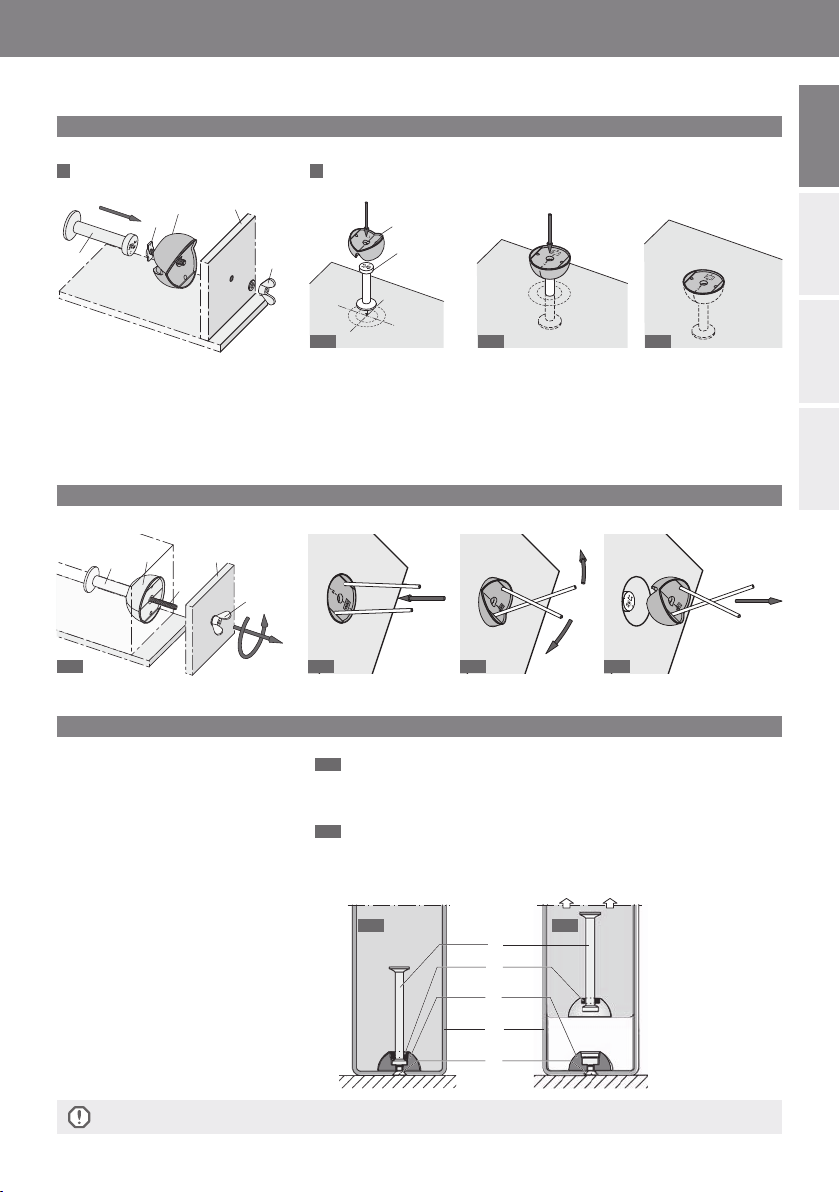
B1 Spherical head lifting anchor type 6000
The HALFEN DEHA Spherical head
transport anchors and the specified
additional reinforcement have to be
installed according to the engineers
drawing. The specified load class
and length are to be observed.
The spherical head lifting anchors
are installed in the mould by using
HALFEN DEHA Recess formers
(see fig. part A).
After the concrete of the precast
element is hardened, the recess
former is removed (see fig. part A).
If corrosion protection is required
for the anchor, the recess has to be
filled with mortar after the installation
of the element. Alternatively, the
available products in galvanised
steel or stainless steel can be used.
The assembly plan, which specifies
the required concrete strength, the
direction of tension loads relative to
the anchor and the design of the
spreader beam, must be followed.
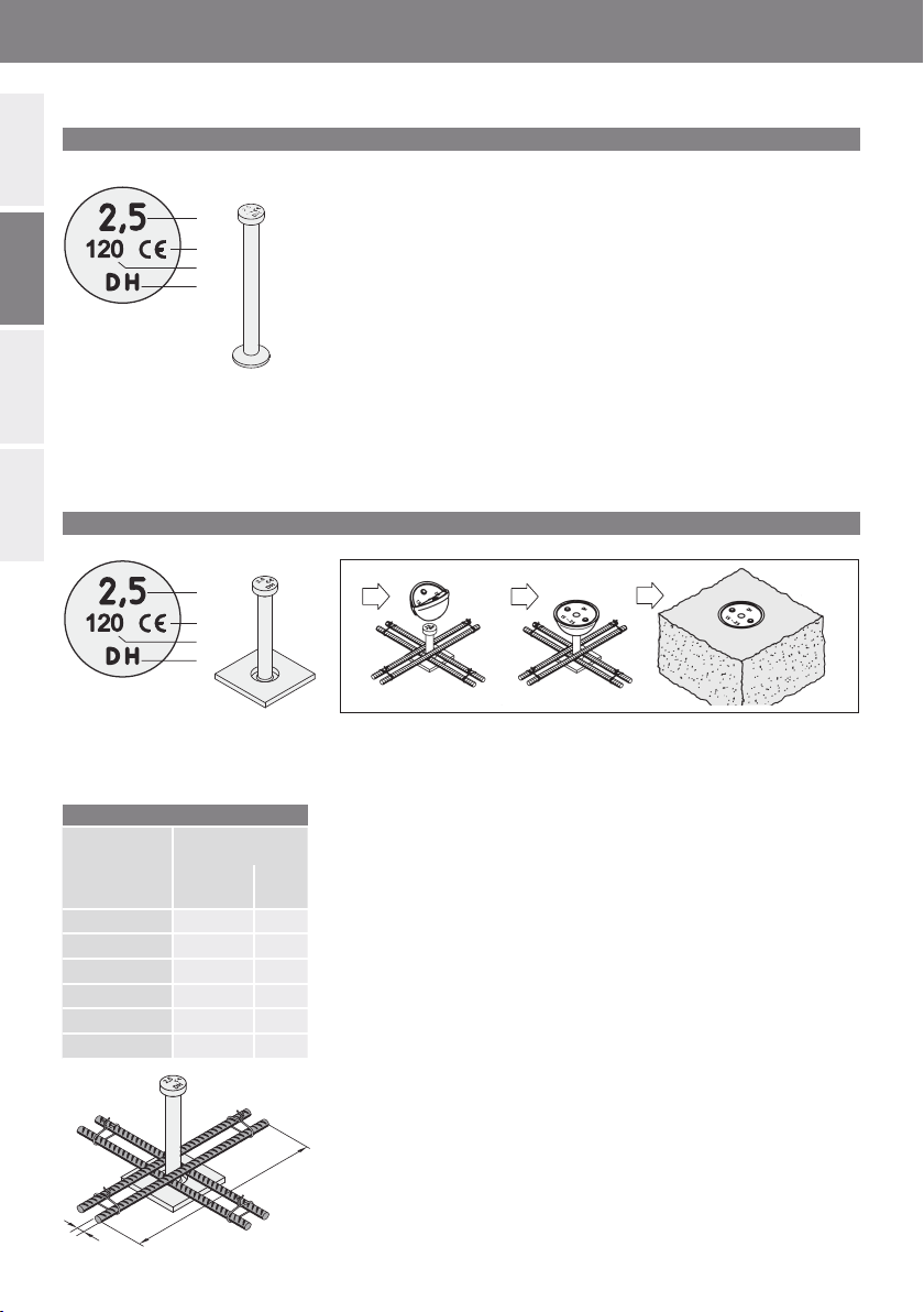
B2 Spherical head plate anchor type 6010
The HALFEN DEHA Spherical head
plate anchors have to be installed
according to the engineers plans.
The specified load group and length
are to be observed. The anchors are
installed in the mould by using
HALFEN DEHA Recess formers, as
shown in part A (see also instructions
KKT-A for the recess formers).
Additional reinforcement must be
installed, the appropriate
reinforcement bars (dimensions see
table) must be arranged crosswise
over the foot plate of the anchor, as
shown in the drawings. Make sure,
that the reinforcement bars bear
directly on the plate.
After the concrete of the precast
element is hardened, the recess
former is removed (see description
part A). If corrosion protection is
required for the anchor, the recess
is to be filled with mortar after the
installation of the element.
Identification of the anchor:
Load class
CE marking
Manufacturer mark
Anchor length [mm]
Identification of the anchor:
Load class
CE marking
Manufacturer mark
Anchor length [mm]
Required additional reinforcement
Designation Additional
reinforcement
ds
[mm]
Ls
[mm]
6010-2,5-0055 4 × ∅ 8 200
6010-2,5-0120 4 × ∅ 10 300
6010-5,0-0065 4 × ∅ 12 450
6010-5,0-0110 4 × ∅ 12 450
6010-10,0-0115 4 × ∅ 16 600
6010-10,0-0150 4 × ∅ 16 600
Alternatively, the available products
in galvanised steel or stainless steel
can be used. The assembly plan,
which specifies the required concrete
strength, the direction of tension
loads relative to the anchor, the
design of the spreader beam, must
be followed. The slab must be
designed as load case “handling”.
5
© 2023 HALFEN · INST_KKT-E 02/23 · www.halfen.com
HALFEN KKT-E Assembly Instructions
Deutsch EnglishFrançais
Polski

Contact with
eye hole
edge required Additional
reinforce-
ment
Ls30°
∅ ds
6002
Connector
ties
SPA-N
6052
B4 Spherical head eye lifting anchor type 6000
The HALFEN DEHA Spherical head eye
anchor and the specified additional
reinforcement must be installed
according to the drawing of the
precast element. The additional
reinforcement bar is inserted through
the eye hole (see fig.). It must be in
contact with the surface of the hole
edge in direction to the tension force.
Dimensions of the reinforcement bar
acc. to EC2 are shown in the table; the
ribbed bar in steel grade B500B acc.
to DIN 488 is bent to an angle of 30°.
B5 Spherical head lifting anchors, cranked, for sandwich panels
Drawing below:
Installation of HALFEN DEHA Offset
Spherical head Anchors in reinforced
concrete sandwich panels.
The Spherical head anchors have to
be installed acc. to the engineers
specification. The anchor head must
be placed in the axis of gravity of the
concrete sandwich panel, and the
foot of the anchor has to be placed in
the centre of the load bearing slab
(see drawing) to ensure that the loads
are securely introduced.
The anchor should be held into
position firmly during the pouring of
the concrete, e.g. by fastening to the
reinforcement. Some tie pins type
HALFEN SPA-N (see Technical Product
Information – HALFEN Sandwich
panel anchors) should be arranged
close to the head of the anchor,
acc. to the drawing adjacent. After
concreting of the precast element the
recess former is removed (see part A).
Designation Load
capacity
Min.
element
thickness
Fabric rein-
forcement
on both
sides
∅ ds
Additional reinforcement
at concrete strength
[N/mm²]
15 25 35
[kN] [mm] [mm] [mm] Ls[mm]
6001-1,3-0065 13 80 Q131 10 650 510 420
6001-2,5-0090 25 80 Q131 12 1000 800 650
6001-5,0-0120 50 100 Q257 16 1700 1350 1100
6001-10,0-0180 100 140 Q257 20 2000 1600 1300
6001-20,0-0250 200 160 Q257 32 3000 2400 1950
Load class
CE marking
Manufacturer mark
After the concrete of the precast
element is hardened, the recess
former is removed (see description
part A).
If corrosion protection is required for
the anchor, the recess has to be filled
with mortar after the installation of
the element.
Identification of the anchor:
Load class
CE marking
Manufacturer mark
Anchor length (only 6002) [mm]
..........
d/2 d/2d/2 d/2
dd
6© 2023 HALFEN · INST_KKT-E 02/23 · www.halfen.com
HALFEN KKT-E Assembly Instructions
Deutsch EnglishFrançaisPolski

B6 Spherical head rod anchor type 6050
B7 Quick fitting spherical head anchor type 6073
B8 Spherical head tilt-up anchors type 6006
The HALFEN DEHA Spherical head
tilt-up anchor has to be installed in
such a way that loads occur only in
axial or perpendicular direction
(see fig. at right). For tilting-up an
additional reinforcement (see figures
below) is necessary. To allow the
tilting-up also to the other side
opposite to the mould, a 2nd inverse
additional reinforcement is required.
The Tilt-up anchor is installed using a
The HALFEN DEHA Spherical head
rod anchors have to be installed
according to the engineers drawing.
The specified load class and length
must be observed. They are installed
in the mould by using appropriate
HALFEN DEHA Recess formers
(see part A). When the concrete is
hardened, the recess former is removed
(see part A). If a corrosion protection
of the anchor is required, the void
must be filled with mortar after the
The load capacity is the same as for
standard anchors type 6000 and the
anchor suits the same lifting links.
The anchor is used with DSM recess
formers code 6126; 6127 and 6128.
Usually the anchor is pushed into the
former with an oil based lubricant.
Recess former type 6134
Additional
rein-
forcement
Position of the
coupler tongue
Lifting link
Designation Length
Element
thickness
dmin
Fabric
reinforce-
ment
Additional
reinforcement Allow. Load
central pull,
shear
∅ dsL1
[mm] [mm] [mm²/m] [mm] [mm]
6006-2,5-0240 240 100 131 10 500 see KKT-E
6006-5,0-0240 240 140 2 x 131 12 750
final installation of the element on
the site.
The assembly plan, which specifies
the required concrete strength, the
direction of tension loads relative to
the anchor and the design of the
spreader beam, must be followed.
special recess former (designation
6134). After the concreting of the
precast element the recess former
is removed (see page 2). For lifting
a spreader beam must be used.
Additional
reinforcement
Lifting anchor 6006
L1
dS
dmin
Identification of the anchor:
Load class
CE marking
Manufacturer mark
Identification of the anchor:
Load class
CE marking
Manufacturer mark
Anchor length [mm]
..........
Load class
CE marking
Manufacturer mark
7
© 2023 HALFEN · INST_KKT-E 02/23 · www.halfen.com
HALFEN KKT-E Assembly Instructions
Deutsch EnglishFrançais
Polski

Teil A: Montageablauf für alle Typen
Einbau mit Gummi-Aussparungskörper
4. Einbau mit Stahl-Aussparungskörper
1An der Schalung 2Von oben in den frischen Beton
3. Gummi-Aussparungskörper nach Erhärten des Betons entfernen
Wenn der Einbau nachträglich von oben in den frischen Beton erfolgt, wird der
Aussparungskörper zusammen mit dem zuvor befestigten HALFEN DEHA Anker
an der vorgesehenen Stelle unter leichtem Rütteln in den Beton eingedrückt,
bis die Oberkante des Aussparungskörpers mit der Oberfläche des Betons bündig
ist. Die Anwendung von Schalfetten, insbesondere im Innenbereich des Ausspa-
rungskörpers, erleichtert das Ausschalen und verbessert dessen Lebensdauer.
Die Stahl-Aussparungskörper werden
verwendet, wenn der Kugelkopf-
Transportranker nach dem Betonieren
nicht zugänglich ist. Sie sind für zwei
Befestigungsarten lieferbar:
– für Befestigung mit Befestigungs-
schraube (Stahl- oder Holzschalung)
und
– für Magnetbefestigung an Stahl-
schalung, wenn keine Löcher
gebohrt werden können.
Wird der Aussparungskörper zum
horizontalen Einbau eines Trans-
portankers verwendet, sind Maß-
nahmen erforderlich, die ein Heraus-
rutschen des Transportankers beim
Rüttelvorgang verhindern (z. B. Befe-
stigen des Ankers an der Schalung,
Festklemmen mit Abstandhaltern
oder Anrödeln an der Bewehrung).
Beachten Sie auch die Montageanleitung KKT-A für die Aussparungskörper!
Befestigungsteile
Schalung
Aussparungskörper
Kugelkopf-Transportanker
Frischer Beton
2.1
3.1 3.2 3.3 3.3
2.2 2.3
Gummi-Manschette
4.1 4.2
Nach dem Ausschalen ist die Gummi-
Manschette vom einbetonierten
Kugelkopf-Transportanker zu entfer-
nen.
4.1 Stahl-Aussparungskörper
plus Kugelkopf-Transportanker,
fertig zum Betonieren
eingebaut.
4.2 Ausheben des Fertigteils
aus der Schalung.
Hilfswerkzeug, z.B. Bewehrungsstab
8© 2023 HALFEN · INST_KKT-E 02/23 · www.halfen.com
Deutsch EnglishFrançais
HALFEN KKT-E Montageanleitung
Polski

Bewehrung in Wänden
Last-
klasse
1
Grund-
bewehrung
kreuzweise
2
Steckbügel
(2-schnittig)
B500B
3
Rand-
bewehrung
B500B
4
Schrägzugbügel
B500B
bei Axialzug ≤ 30° [β] bei Schrägzug > 30° [β] beidseitig
dsl1dsl1ds2 ds1 dbr1 ls1
[mm2/m] Stck. [mm] [mm] Stck. [mm] [mm] [mm] [mm] [mm] [mm]
1,3 2 × 60 ≥ 2 ∅6 300 ≥ 2 ∅6 450 ∅10 ∅8 25 800
2,5 2 × 100 ≥ 2 ∅8 610 ≥ 4 ∅8 610 ∅ 10 ∅ 10 25 1500
5,0 2 × 140 ≥ 2 ∅10 720 ≥ 4 ∅10 720 ∅ 12 ∅14 35 2000
7,5 2 × 160 ≥ 4 ∅10 720 ≥ 6 ∅10 720 ∅ 12 ∅16 40 2300
10,0 2 × 180 ≥ 4 ∅10 720 ≥ 8 ∅ 10 720 ∅ 14 ∅20 50 2600
15,0 2 × 240 ≥ 4 ∅12 800 ≥ 6 ∅ 12 1000 ∅14 ∅25 80 3000
20,0 2 × 350 ≥ 6 ∅12 1000 ≥ 10 ∅ 12 1000 ∅16 ∅28 90 3400
32,0 2 × 400 ≥ 8 ∅12 1000 ≥ 10 ∅ 14 1100 ∅16 2 × ∅ 25 80 3000
45,0 2 × 500 ≥ 10 ∅14 1400 ≥ 12 ∅ 14 1440 ∅20 2 × ∅ 28 80 3400
1
1
2
2
3
4
4
4
Der Biegerollendurchmesser gemäß
DIN 488 muss für den Schrägzug-
bügel nicht eingehalten werden.
Einzubauende Bewehrung im Bereich der Transportanker
Die Schrägzugbewehrung ist
möglichst dicht am Aussparungs-
körper und mit Druckkontakt am
Anker anzuordnen.
Bewehrter Bereich
≥ 3-fache Ankerlänge L
Randbewehrung
Schrägzugbügel
immer entgegen
der Kraftrichtung
einlegen.
ls= l1+ Ankerlänge
Steckbügel möglichst dicht am Anker anordnen
kreuzweise Bewehrung
Schrägzugbewehrung ls1 = Gesamtlänge
(ca. 2x Schenkellänge)
e∼15cm
ds2
dbr
ez/2
15°
β
15°
15°
l1l
Die jeweils ersten Steckbügel sind
möglichst dicht am Aussparungs-
körper anzuordnen.
Die einzubauende Bewehrung ist vom Tragwerksplaner festzulegen!
4
≤ 30°
30°- 60°
9
© 2023 HALFEN · INST_KKT-E 02/23 · www.halfen.com
Deutsch EnglishFrançais
HALFEN KKT-E Montageanleitung
Polski

123
120
Ls
ds
120
Teil B: Produktbezogene Informationen
B1 Kugelkopf-Transportanker Typ 6000
HALFEN DEHA Kugelkopf-Trans-
portanker und die angegebene
Zulagebewehrung sind gemäß der
Fertigteilzeichnung einzubauen.
Die Lastgruppe und Länge des Ankers
sind zu beachten. Die Kugelkopf-
Transportanker werden mit Hilfe von
HALFEN DEHA Aussparungskörpern
in die Schalung eingebaut (siehe
Bilder Teil A). Wenn der Beton des
Fertigteils ausreichend erhärtet ist,
wird der Aussparungskörper entfernt
(siehe Bilder Teil A).
Ist ein Korrosionsschutz für den Anker
erforderlich, so ist die Aussparung
nach dem Einbau des Fertigteils mit
Mörtel zu verfüllen. Alternativ können
die lieferbaren Produkte in verzinkter
Ausführung bzw. aus nichtrostendem
Stahl eingesetzt werden.
Der Montageplan gibt die Beton-
druckfestigkeit, die Zugrichtung in
Bezug auf den Anker, Ausführung
und Art von Traversen etc. an und
ist einzuhalten.
B2 Kugelkopf-Plattenanker Typ 6010
Die HALFEN DEHA Kugelkopf-Platten-
anker sind gemäß der Fertigteilzeich-
nung einzubauen. Dabei sind Last-
gruppe und Länge des Ankers zu be-
achten. Die Plattenanker werden mit
Hilfe der HALFEN DEHA Aussparungs-
körper in die Schalung eingebaut wie
in Teil A dargestellt (siehe auch Mon-
tageanleitung KKT-A für die Ausspa-
rungskörper).
Als zusätzliche Bewehrung sind Be-
wehrungsstäbe gem. nebenstehender
Tabelle kreuzweise über der Platte an-
zuordnen, siehe Bild. Dabei ist darauf
zu achten, dass die Bewehrungsstäbe
direkt auf der Platte aufliegen.
Nach dem Erhärten des Betons wird
der Aussparungskörper entfernt, siehe
Beschreibung in Teil A.
Ist ein Korrosionsschutz für den Anker
erforderlich, so ist die Aussparung
nach dem Einbau des Fertigteils mit
Mörtel zu verfüllen.
Kennzeichnung Ankerkopf:
Lastklasse
CE-Zeichen
Herstellerkennzeichen
Ankerlänge [mm]
Kennzeichnung Ankerkopf:
Lastklasse
CE-Zeichen
Herstellerkennzeichen
Ankerlänge [mm]
Alternativ können die lieferbaren Pro-
dukte in verzinkter Ausführung bzw.
aus nichtrostendem Stahl eingesetzt
werden. Der Montageplan gibt die
Betondruckfestigkeit, die Zugrichtung
in Bezug auf den Anker, Ausführung
und Art von Traversen etc. an und ist
einzuhalten.
Die Platte ist für den Lastfall „Trans-
port“ zu bemessen.
Erforderliche Zulagebewehrung
Artikel-
bezeichnung Zulagebewehrung
ds
[mm]
Ls
[mm]
6010-2,5-0055 4 × ∅ 8 200
6010-2,5-0120 4 × ∅ 10 300
6010-5,0-0065 4 × ∅ 12 450
6010-5,0-0110 4 × ∅ 12 450
6010-10,0-0115 4 × ∅ 16 600
6010-10,0-0150 4 × ∅ 16 600
10 © 2023 HALFEN · INST_KKT-E 02/23 · www.halfen.com
Deutsch EnglishFrançais
HALFEN KKT-E Montageanleitung
Polski

Kontakt
mit der
Lochlaibung Zulage-
bewehrung
Ls30°
∅ ds
6002
Verbund-
nadeln
SPA-N
6052
B4 Kugelkopf-Augenanker Typ 6001
HALFEN DEHA Kugelkopf-Augenanker
und die angegebene Zulagebewehrung
sind gemäß der Fertigteilzeichnung
einzubauen. Der Zulage-Bewehrungs-
stab ist so einzubauen, dass er fest
in der unteren Ausrundung anliegt
und ein Kontakt besteht (siehe Bild).
Die Abmessungen der Zulage-
bewehrung nach EC2 sind der Tabelle
zu entnehmen. Die Bewehrungsstäbe
aus gerippten B500B nach DIN 488
werden zu einem Winkel von 30°
gebogen. Nach dem Erhärten des
Betons wird der Aussparungskörper
entfernt, siehe Beschreibung in Teil A.
B5 Kugelkopf-Transportanker, gekröpft, für Sandwich-Platten
Zeichnung unten:
Einbau von gekröpften HALFEN
DEHA Kugelkopf-Transportankern in
Stahlbeton-Sandwichplatten.
Die Anker sind gemäß der Fertigteil-
zeichnung und den Angaben des
Planers einzubauen. Der Ankerkopf
befindet sich nach dem Einbau an
der Innenseite der Tragschicht in der
Schwerachse der Mehrschichtenplatte
und der Fuß zur sicheren Lastein-
leitung in der Tragschichtmitte, siehe
Bild.
Durch Anrödeln des Kugelkopfankers
an der Bewehrung wird der Anker
während des Betonierens in der rich-
tigen Lage gehalten. Im Kopfbereich
des Ankers sind einige HALFEN SPA-N
Verbundnadeln (vgl. Produktinformati-
on Technik – HALFEN Sandwichplat-
tenanker) angeordnet, siehe Bild.
Nach dem Erhärten des Betons wird
der Aussparungskörper entfernt, siehe
Beschreibung in Teil A.
Artikel-
bezeichnung
Zul.
Trag-
fähigkeit
Mindest-
bauteil-
dicke
Mattenbe-
wehrung
beidseitig
∅ds
Zulagebewehrung
bauseits bei
Betondruck-
festigkeit [N/mm²]
15 25 35
[kN] [mm] [mm] [mm] Ls [mm]
6001-1,3-0065 13 80 Q131 10 650 510 420
6001-2,5-0090 25 80 Q131 12 1000 800 650
6001-5,0-0120 50 100 Q257 16 1700 1350 1100
6001-10,0-0180 100 140 Q257 20 2000 1600 1300
6001-20,0-0250 200 160 Q257 32 3000 2400 1950
Lastklasse
CE-Zeichen
Herstellerkennzeichen
Lastklasse
CE-Zeichen
Herstellerkennzeichen
Ankerlänge (nur 6002) [mm]
Ist ein Korrosionsschutz für den Anker
erforderlich, so ist die Aussparung
nach dem Einbau des Fertigteils mit
Mörtel zu verfüllen.
..........
d/2 d/2d/2 d/2
dd
11
© 2023 HALFEN · INST_KKT-E 02/23 · www.halfen.com
Deutsch EnglishFrançais
HALFEN KKT-E Montageanleitung
Polski

B6 Kugelkopf-Stabanker Typ 6050
B7 DSM Schnellmontageanker 6073
B8 Kugelkopf-Aufstellanker 6006
Der HALFEN DEHA Kugelkopf-Aufstel-
lanker muss so eingebaut werden,
dass er nur axial oder quer belastet
wird (Bild rechts). Zum Aufstellen ist
eine Zulagebewehrung (Bilder und
Tabelle unten) erforderlich. Um ein
späteres Aufstellen von der schalungs-
abgewandten Seite zu ermöglichen
muß die Grund- und Zulagebeweh-
rung nochmals spiegelbildlich einge-
baut werden. Für den Einbau wird der
HALFEN DEHA Kugelkopf-Stabanker
sind gemäß der Fertigteilzeichnung
einzubauen. Die Lastgruppe und
Länge des Ankers sind zu beachten.
Die Kugelkopf-Transportanker werden
mit Hilfe von HALFEN DEHA
Aussparungskörpern in die Schalung
eingebaut (siehe Beschreibung Teil A).
Wenn der Beton des Fertigteils
ausreichend erhärtet ist, wird der
Aussparungskörper entfernt (siehe
Beschreibung Teil A).
Der DSM Schnellmontageanker kann
einfach und problemlos in Situationen
eingesetzt werden, bei denen der
Aussparungskörper an der Schalung
verbleiben muss (z.B. Deckenherstel-
lung im Negativ-Verfahren, Überkopf-
Produktion von Schachtunterteilen
und Einbau in Treppenwangen).
Der Anker wird mit etwas Fett einfach
in den DSM-Aussparungskörper
gesteckt.
Lastklasse
CE-Zeichen
Herstellerkennzeichen
Lastklasse
CE-Zeichen
Herstellerkennzeichen
Ankerlänge [mm]
Lastklasse
CE-Zeichen
Herstellerkennzeichen
Aussparungskörper 6134
Zulage-
bewehrung
Position der
Kupplungslasche
Abhebekupplung
Artikel-
bezeichnung Länge
Bauteil-
dicke
dmin
Matten-
beweh-
rung
Zulagebewehrung Zulässige
Belastung
zentr. Zug,
Querzug
∅ dsL1
[mm] [mm] [mm²/m] [mm] [mm]
6006-2,5-0240 240 100 131 10 500 Siehe KKT-E
6006-5,0-0240 240 140 2 x 131 12 750
Ist ein Korrosionsschutz für den Anker
erforderlich, so ist die Aussparung
nach dem Einbau des Fertigteils mit
Mörtel zu verfüllen. Der Montageplan
gibt die Betondruckfestigkeit, die
Zugrichtung in Bezug auf den Anker,
Ausführung und Art von Traversen
etc., an und ist einzuhalten.
spezielle Aussparungskörper Typ 6134
verwendet. Nach dem Betonieren
wird dieser, sinngemäß wie in Teil A
dargestellt, entfernt. Zum Heben ist
eine Traverse zu verwenden.
Zulagebewehrung Transportanker 6006
L1
dS
dmin
..........
12 © 2023 HALFEN · INST_KKT-E 02/23 · www.halfen.com
Deutsch EnglishFrançais
HALFEN KKT-E Montageanleitung
Polski

Partie A: procédure d’installation pour tous les types
Installation avec réservation en caoutchouc
4. Installation avec réservation en acier
1Contre le coffrage 2Par le dessus dans le béton frais
3. Retrait de la réservation en caoutchouc une fois le béton durci.
Si l’installation se fait par le dessus après coulage de béton frais, la réservation
avec l’ancre à tête hémisphérique HALFEN DEHA pré-assemblée sera insérée à la
position spécifiée en la poussant et en la faisant osciller légèrement jusqu’à ce
que son bord supérieur affleure la surface du béton. L’application de lubrifiant
pour coffrage, en particulier sur l’intérieur de la réservation, se révèlera utile pour
le décoffrage et pour améliorer la durée de service de la réservation.
Dans les cas où l’élément préfabriqué
doit être sorti du coffrage sans avoir
accès à la réservation, des réserva-
tions en acier doivent être utilisées.
Deux options de fixation existent :
- fixation avec boulons de fixation
(coffrage acier ou bois) et
- fixation magnétique aux coffrages en
acier sur lesquels il est impossible de
percer des trous.
Si ce type de réservation est utilisé
pour positionner l’ancre horizontale-
ment dans le coffrage, des mesures
doivent être prises pour empêcher
l’ancre de se déloger lors du coulage
du béton (par ex. en la fixant au ren-
forcement ou en la maintenant au
moyen de distanceurs).
Après décoffrage, l’œillet en caout-
chouc est retiré de l’ancre de le-
vage HALFEN DEHA coulée.
4.1 4.1 Réservation et ancre de
transport à tête hémisphérique
installés, prêts pour le coulage.
4.2 4.2 Décoffrage de l’élément
préfabriqué par levage.
Voir aussi les instructions KKT-A pour la réservation!
Éléments de fixation
Coffrage
Réservation
Ancre de levage à tête hémisphérique
Béton frais
2.1
3.1 3.2 3.3 3.3
2.2 2.3
Œillet en caoutchouc
4.1 4.2
Outillage auxiliaire (barre de renfort par ex.)
13
© 2023 HALFEN · INST_KKT-E 02/23 · www.halfen.com
Deutsch EnglishFrançais
Polski
HALFEN KKT-E Notice d‘utilisation

Reinforcement in walls
Classe
de
charge
1
Renforce-
ment en
treillis à
maille
carrée
2
Armature en U
B500B
3
Renforcement
du bord
B500B deux
côtés
4
Étrier de traction
diagonale B500B
pour traction axiale ≤ 30°[β] pour traction diagonale > 30°[β]
dsl1dsl1ds2 ds1 dbr1 ls1
[mm2/m] Pièces [mm] [mm] Pièces [mm] [mm] [mm] [mm] [mm] [mm]
1,3 2 × 60 ≥ 2 ∅ 6 300 ≥ 2 ∅6 450 ∅10 ∅8 25 800
2,5 2 × 100 ≥ 2 ∅ 8 610 ≥ 4 ∅ 8 610 ∅10 ∅10 25 1500
5,0 2 × 140 ≥ 2 ∅ 10 720 ≥ 4 ∅10 720 ∅ 12 ∅14 35 2000
7,5 2 × 160 ≥ 4 ∅10 720 ≥ 6 ∅ 10 720 ∅ 12 ∅16 40 2300
10,0 2 × 180 ≥ 4 ∅10 720 ≥ 8 ∅10 720 ∅ 14 ∅20 50 2600
15,0 2 × 240 ≥ 4 ∅12 800 ≥ 6 ∅ 12 1000 ∅14 ∅25 80 3000
20,0 2 × 350 ≥ 6 ∅ 12 1000 ≥ 10 ∅12 1000 ∅ 16 ∅28 90 3400
32,0 2 × 400 ≥ 8 ∅ 12 1000 ≥ 10 ∅14 1100 ∅ 16 2 × ∅ 25 80 3000
45,0 2 × 500 ≥ 10 ∅ 14 1400 ≥ 12 ∅ 14 1440 ∅20 2 × ∅ 28 80 3400
1
1
2
2
3
4
4
4
4
Le rayon de courbure conf. DIN 488
n’est pas obligatoire pour l’armature
en U diagonale.
Renforcement supplémentaire au niveau des positions de l’ancre de levage
Le renforcement de traction diago-
nale doit être placé aussi près que
possible sous la réservation et avoir
un contact total avec l’ancre.
Zone de renfort ≥ 3 fois
la longueur L de l’ancre
Renforcement du bord
Insérez toujours le
renforcement de
traction diagonale
dans le sens oppo-
sé à celui de la
charge.
ls= l1+ l
(Longueur de
l’attache coulée)
Armature en U (aussi proche que possible de l’ancre)
Renforcement en treillis à maille carrée
Renforcement de traction
diagonale
ls1 = longueur totale (approx.
2 fois la longueur de patte)
e∼15cm
ds2
dbr
ez/2
15°
β
15°
15°
l1l
La première armature en U de chaque
côté doit être aussi proche que possi-
ble de la réservation.
L’installation d’un renforcement doit toujours être conforme aux spécifications de l’ingénieur en mécanique statique
responsable!
≤ 30°
30°– 60°
14 © 2023 HALFEN · INST_KKT-E 02/23 · www.halfen.com
Deutsch EnglishFrançaisPolski
HALFEN KKT-E Notice d‘utilisation

123
120
Ls
ds
120
Partie B: informations spécifiques sur le produit
B1 Ancre de levage à tête hémisphérique type 6000
Les ancres de transport à tête hé-
misphérique HALFEN DEHA et le
renfort supplémentaire spécifié
doivent être installés conformément
au schéma d’ingénierie. La classe de
charge et la longueur spécifiées
doivent être respectées. Les ancres
de levage à tête hémisphérique sont
installées dans le coffrage au moyen
de réservations HALFEN DEHA (voir
fig. partie A).
Une fois que le béton de l’élément
préfabriqué a durci, la réservation
peut être retirée (voir fig. partie A).
Si une protection anticorrosion pour
l’ancre est requise, la réservation
doit être remplie de mortier après
l’installation de l’élément. Sinon,
des produits en acier galvanisé ou
en acier inox disponibles peuvent
être utilisés.
Le plan d’assemblage, qui spécifie la
résistance requise du béton, le sens
des charges de traction par rapport
à l’ancre et la conception du palon-
nier, doit être suivi.
B2 Ancre à semelle carrée à tête hémisphérique type 6010
Les ancres à semelle carrée à tête
hémisphérique HALFEN DEHA
doivent être installées conformément
aux plans d’ingénierie.
La classe de charge et la longueur
spécifiées doivent être respectées.
Les ancres doivent être installées
dans le coffrage au moyen de réser-
vations HALFEN DEHA, comme indi-
qué à la partie A (voir aussi les ins-
tructions KKT-A pour les réserva-
tions).
Un renforcement supplémentaire
doit être installé, des armatures de
renfort adéquates (voir dimensions
dans le tableau) doivent être dispo-
sées en croix au-dessus de la semelle
de l’ancre, comme indiqué sur les
schémas. Assurez-vous que les arma-
tures de renfort reposent directement
sur la semelle.
Une fois que le béton de l’élément
préfabriqué a durci, la réservation
peut être retirée (voir description
partie A).
Identification de l’ancre:
Classe de charge
Marquage CE
Marquage fabricant
Longueur de l’ancre [mm]
Renforcement supplémentaire requis
Désignation Armature de renfort
supplémentaire
ds
[mm]
Ls
[mm]
6010-2.5-0055 4 × ∅ 8 200
6010-2.5-0120 4 × ∅ 10 300
6010-5.0-0065 4 × ∅ 12 450
6010-5.0-0110 4 × ∅ 12 450
6010-10.0-0115 4 × ∅ 16 600
6010-10.0-0150 4 × ∅ 16 600
Si une protection anticorrosion pour
l’ancre est requise, la réservation doit
être remplie de mortier après l’instal-
lation de l’élément. Sinon, des pro-
duits en acier galvanisé ou en acier
inox disponibles peuvent être utilisés.
Le plan d’assemblage, qui spécifie la
résistance requise du béton, le sens
des charges de traction par rapport à
l’ancre et la conception du palonnier,
doit être suivi. La dalle doit être
conçue pour la « manipulation » d’un
cas de charge.
Identification de l’ancre:
Classe de charge
Marquage CE
Marquage fabricant
Longueur de l’ancre [mm]
15
© 2023 HALFEN · INST_KKT-E 02/23 · www.halfen.com
Deutsch EnglishFrançais
Polski
HALFEN KKT-E Notice d‘utilisation

Contact with
eye hole
edge required renforcement
supplémentaire
Ls30°
∅ ds
6002
Attaches de
liaison SPA-N
6052
B4 Ancre de levage à œil à tête hémisphérique type 6000
Les ancres à œil à tête hémisphérique
HALFEN DEHA et l’armature de ren-
fort supplémentaire spécifiées doivent
être installées conformément au sché-
ma de l’élément préfabriqué. L’arma-
ture de renfort supplémentaire doit
être insérée dans l’œil (voir fig.). Elle
doit être en contact avec le bord de
l’orifice dans le sens de la force de
traction. Les dimensions de l’armature
de renfort selon EC2 sont indiquées
dans le tableau: la barre nervurée en
acier grade B 500 B conf. DIN 488
B5 Ancres de levages à tête hémisphérique, contre-coudées, pour panneaux sandwichs
Schéma ci-dessous:
Installation d’ancres contre-coudées à
tête hémisphérique HALFEN DEHA
dans des panneaux sandwich en
béton renforcé
Ces ancres à tête hémisphérique
doivent être installées conformément
aux spécifications d’ingénierie. La tête
de l’ancre doit être placée dans l’axe
de gravité du panneau sandwich en
béton et le pied de l’ancre doit être
au centre de la dalle de support de
charge (voir schéma) pour garantir
que les charges soient reprises en
toute sécurité.
L’ancre doit être maintenue ferme-
ment en place durant le coulage du
béton, en la fixant par ex. à l’arma-
ture de renfort. Les attaches de liai-
son de type HALFEN SPA-N (voir
Fiche d’information produit – Ancres
pour panneaux sandwichs HALFEN)
doivent être disposées près de la tête
de l’ancre, comme sur le schéma
adjacent.
Une fois que l’élément préfabriqué est
coulé, la réservation peut être retirée
(voir partie A).
Désignation
Capacité
de
charge
Épaisseur
minimale
de
l’élément
Renforce-
ment en
tissu des
deux côtés
∅ ds
Armature de renfort
supplémentaire ayant la
résistance du béton
[N/mm²]
15 25 35
[kN] [mm] [mm] [mm] Ls[mm]
6001-1.3-0065 13 80 Q131 10 650 510 420
6001-2.5-0090 25 80 Q131 12 1000 800 650
6001-5.0-0120 50 100 Q257 16 1700 1350 1100
6001-10.0-0180 100 140 Q257 20 2000 1600 1300
6001-20.0-0250 200 160 Q257 32 3000 2400 1950
est cintrée selon un angle de 30°.
Une fois que le béton de l’élément
préfabriqué a durci, la réservation
peut être retirée (voir description
partie A).
Si une protection anticorrosion pour
l’ancre est requise, la réservation doit
être remplie de mortier après l’instal-
lation de l’élément.
Identification de l’ancre:
Classe de charge
Marquage CE
Marquage fabricant
Longueur de l’ancre (6002 uniquement) [mm]
..........
d/2 d/2d/2 d/2
dd
Identification de l’ancre:
Classe de charge
Marquage CE
Marquage fabricant
16 © 2023 HALFEN · INST_KKT-E 02/23 · www.halfen.com
Deutsch EnglishFrançaisPolski
HALFEN KKT-E Notice d‘utilisation

B6 Ancre à tige nervurée à tête hémisphérique type 6050
B7 Ancre à tête hémisphérique à insertion rapide type 6073
B8 Ancres basculantes à tête hémisphérique type 6006
L’ancre basculante à tête hémisphé-
rique HALFEN DEHA doit être installée
de manière à ce que les charges s’ap-
pliquent dans le sens axial ou perpendi-
culaire uniquement (voir fig. de droite).
Elle est nécessaire pour le basculement
d’une armature de renfort supplémen-
taire (voir les figures ci-dessous).
Pour permettre un basculement du
côté opposé au coffrage également,
une 2e armature de renfort inversée
supplémentaire est requise. Cette ancre
Les ancres à tige nervurée à tête
hémisphérique HALFEN DEHA
doivent être installées conformément
au schéma d’ingénierie.
La classe de charge et la longueur
spécifiées doivent être respectées.
Ces ancres doivent être installées dans
le coffrage au moyen de réservations
HALFEN DEHA adéquates (voir partie
A). Une fois le béton durci, la
réservation peut être retirée (voir
partie A). Si une protection
Sa capacité de charge est la même
que celle des ancres standard type
6000 et cette ancre est utilisable avec
les mêmes maillons de levage.
Elle s’utilise avec des réservations
DSM codes 6126, 6127 et 6128.
Généralement, l’ancre est poussée
dans la réservation en utilisant un lu-
brifiant à base d’huile.
Réservation type 6134
Armature
de
renfort sup-
plémentaire
Position de l’ergot
de couplage
Maillon de levage
Désignation Longueur
Épaisseur
de
l’élément
dmin
Renforce-
ment en
tissu
Armature de ren-
fort supplémentaire
Traction cen-
trale de
charge ad-
miss., cisaille-
ment
∅ dsL1
[mm] [mm] [mm²/m] [mm] [mm]
6006-2,5-0240 240 100 131 10 500 Voir KKT-E
6006-5,0-0240 240 140 2 x 131 12 750
anticorrosion pour l’ancre est requise,
l’espace vide laissé devra être rempli
de mortier après l’installation définitive
de l’élément sur le site. Le plan
d’assemblage, qui spécifie la résistance
requise du béton, le sens des charges
de traction par rapport à l’ancre et la
conception du palonnier, doit être
suivi.
basculante doit être installée au moyen
d’une réservation spéciale (désignation
6134). Une fois que l’élément préfabri-
qué est coulé, la réservation peut être
retirée (voir 2). À utiliser pour le levage
d’un palonnier.
Armature de renfort
supplémentaire
Ancre de levage 6006
L1
dS
dmin
..........
Identification de l’ancre:
Classe de charge
Marquage CE
Marquage fabricant
Identification de l’ancre:
Classe de charge
Marquage CE
Marquage fabricant
Longueur de l’ancre [mm]
Identification de l’ancre:
Classe de charge
Marquage CE
Marquage fabricant
17
© 2023 HALFEN · INST_KKT-E 02/23 · www.halfen.com
Deutsch EnglishFrançais
Polski
HALFEN KKT-E Notice d‘utilisation

Część A : Montaż wszystkich typów
Montaż z użyciem gumowej kształtki szalunkowej
4. Montaż z użyciem stalowej kształtki szalunkowej
1Montaż do szalunku 2Montaż z góry, w świeżym betonie
3. Demontaż gumowej kształtki szalunkowej po związaniu betonu
Przy montażu w świeżym betonie, kotwę HALFEN DEHA z głowicą kulową
razem z zamontowaną na niej kształtkę szalunkową umieszczamy w wymaganym
położeniu i wciskamy w beton do momentu aż górna krawędź kształtki
szalunkowej znajdzie się w płaszczyźnie powierzchni betonu.
Dla ułatwienia demontażu i zwiększenia trwałości kształtek szalunkowych zaleca
się nanieść na ich powierzchnie płyn antyadhezyjny.
W przypadku gdy prefabrykat musi
być wyciągnięty z formy, w której nie
ma dostępu do kształtki szalunkowej,
używa się stalowej kształtki.
Możliwe są dwa sposoby mocowania:
• za pomocą śrub mocujących
(stalowa lub drewniana forma)
• magnetyczne, w przypadku gdy
nie można wiercić otworów.
Jeśli taki typ kształtki szalunkowej jest
użyty do umiejscowienia kotwy w
poziomie, należy zabezpieczyć ją
przed przemieszczeniem w trakcie
betonowania (np. przez mocowanie
do zbrojenia albo zabezpieczenie
rozpórkami).
Po rozformowaniu uszczelkę gumową
należy usunąć z kotwy.
Patrz również instrukcja dla kształtek szalunkowych KKT-A!
Elementy mocujące
Szalunek
Kształtka szalunkowa
Kotwa HALFEN DEHA
z głowicą kulową
Beton
2.1
3.1 3.2 3.3 3.3
2.2 2.3
Uszczelka gumowa
4.1 4.2
4.1 Kształtka szalunkowa i kotwa
transportowa z głowicą kulową
gotowe do zabetonowania.
4.2 Wyciąganie prefabrykatu z
formy.
Narzędzie pomocnicze, np. pręt zbrojeniowy
18 © 2023 HALFEN · INST_KKT-E 02/23 · www.halfen.com
Deutsch EnglishFrançaisPolski
HALFEN KKT-E Instrukcja montażu

Zbrojenie ścian
Klasa
obcią-
żenia
1
Siatka
zbrojeniowa
2
Strzemiona otwarte
B500B
3
Zbrojenie
krawędziowe
po obu
stronach
B500B
4
Strzemiona ukośne
B500B
siła osiowa ≤ 30° [β] siła ukośna > 30° [β]
dsl1dsl1ds2 ds1 dbr1 ls1
[mm2/m] szt. [mm] [mm] szt. [mm] [mm] [mm] [mm] [mm] [mm]
1,3 2 × 60 ≥ 2 ∅6 300 ≥ 2 ∅6 450 ∅10 ∅8 25 800
2,5 2 × 100 ≥ 2 ∅8 610 ≥ 4 ∅8 610 ∅ 10 ∅ 10 25 1500
5,0 2 × 140 ≥ 2 ∅10 720 ≥ 4 ∅10 720 ∅ 12 ∅14 35 2000
7,5 2 × 160 ≥ 4 ∅10 720 ≥ 6 ∅10 720 ∅ 12 ∅16 40 2300
10,0 2 × 180 ≥ 4 ∅10 720 ≥ 8 ∅ 10 720 ∅ 14 ∅20 50 2600
15,0 2 × 240 ≥ 4 ∅12 800 ≥ 6 ∅ 12 1000 ∅14 ∅25 80 3000
20,0 2 × 350 ≥ 6 ∅12 1000 ≥ 10 ∅ 12 1000 ∅16 ∅28 90 3400
32,0 2 × 400 ≥ 8 ∅12 1000 ≥ 10 ∅ 14 1100 ∅16 2 × ∅ 25 80 3000
45,0 2 × 500 ≥ 10 ∅14 1400 ≥ 12 ∅ 14 1440 ∅20 2 × ∅ 28 80 3400
1
1
2
2
3
4
4
4
Promień gięcia wg DIN 488 dla
ukośnego strzemienia rozciąganego
nie musi być dotrzymany.
Dodatkowe zbrojenie w obszarze kotwy transportowej
Strzemię na siły poziome musi
byćumieszczone bezpośrednio
pod kształtką szalunkową i
stykać się z kotwą.
Obszar dozbrojenia
≥ 3x długość kotwy L
Zbrojenie krawędziowe
Zbrojenie ukośne
rozciągane zawsze
umieszczać prze-
ciwnie do kierunku
obciążenia.
ls= l1+ dł. kotwy
Strzemiona otwarte (maksymalnie blisko kotwy)
Siatka zbrojeniowa
Rozciągane zbrojenie
ukośne
ls1 = dł. całkowita
(ok. 2x dł. ramienia)
e∼15cm
ds2
dbr
ez/2
15°
β
15°
15°
l1l
Pierwsze strzemię z każdej strony ko-
twy musi być tak blisko kształtki sza-
lunkowej jak to możliwe.
Montaż zbrojenia musi być zgodny z projektem i wytycznymi projektanta!
4
≤ 30°
30°- 60°
19
© 2023 HALFEN · INST_KKT-E 02/23 · www.halfen.com
Deutsch EnglishFrançais
Polski
HALFEN KKT-E Instrukcja montażu

123
120
Ls
ds
120
Część B: Informacje o produkcie
B1 Kotwy transportowe z głowicą kulową typu 6000
Kotwy transportowe z głowicą kulową
HALFEN DEHA i zbrojenie dodatkowe
montować zgodnie z dokumentacją
techniczną. Należy zwrócić uwagę na
grupę obciążenia i długość kotwy.
Kotwy z głowica kulową należy
montować we formach przy użyciu
kształtek szalunkowych HALFEN
DEHA (patrz rysunki w części A).
Po związaniu betonu w prefabrykacie,
kształtki szalunkowe są usuwane
(patrz rys. w części A).
Gdy wymagana jest ochrona antyko-
rozyjna kotwy, gniazdo głowicy kotwy
należy po montażu prefabrykatu
wypełnić zaprawą. Alternatywnie, ko-
twy mogą być dostarczone jako ocyn-
kowane galwanicznie lub ze stali
nierdzewnej.
Należy postępować zgodnie z pro-
jektem montażu, w którym określa się
wymaganą klasę betonu, kierunki
obciążenia kotew, typ trawersu itp.
B2 Kotwy transportowe z głowicą kulową płytowe typu 6010
Kotwy transportowe z głowicą kulową
płytowe należy montować zgodnie z
dokumentacją techniczną. Należy
zwrócić uwagę na grupę obciążenia i
długość kotwy. Kotwy z głowicą
kulową należy montować we formach
przy użyciu kształtek szalunkowych
HALFEN DEHA jak pokazano na
rysunkach w części A (patrz również
instrukcja dla kształtek szalunkowych
KKT-A).
Należy zamontować dodatkowe zbro-
jenie. Właściwe pręty zbrojeniowe
(wymiary- patrz tabela) należy ułożyć
na krzyż na płytce stalowej jak
pokazano na rysunku. Należy zwrócić
uwagę aby pręty zbrojeniowe leżały
bezpośrednio na płytce.
Po związaniu betonu w prefabrykacie,
kształtki szalunkowe są usuwane
(patrz rys. w części A).
Identyfikacja kotwy:
Klasa obciążenia
Znak CE
Znak producenta
Dł. kotwy [mm]
Identyfikacja kotwy:
Klasa obciążenia
Znak CE
Znak producenta
Dł. kotwy [mm]
Gdy wymagana jest ochrona
antykorozyjna kotwy, gniazdo
głowicy kotwy należy po montażu
prefabrykatu wypełnić zaprawą.
Alternatywnie, kotwy mogą być
dostarczone jako ocynkowane
galwanicznie lub ze stali nierdzewnej.
Należy postępować zgodnie z
projektem montażu, w którym określa
się wymaganą klasę betonu, kierunki
obciążenia kotew, typ trawersu itp.
Płytę należy wymiarować na
obciążenia w trakcie podnoszenia
i transportu.
Wymagane zbrojenie dodatkowe
Nr. artykułu Zbrojenie
ds
[mm]
Ls
[mm]
6010-2.5-0055 4 × ∅ 8 200
6010-2.5-0120 4 × ∅ 10 300
6010-5.0-0065 4 × ∅ 12 450
6010-5.0-0110 4 × ∅ 12 450
6010-10.0-0115 4 × ∅ 16 600
6010-10.0-0150 4 × ∅ 16 600
20 © 2023 HALFEN · INST_KKT-E 02/23 · www.halfen.com
Deutsch EnglishFrançaisPolski
HALFEN KKT-E Instrukcja montażu
Table of contents
Languages:
Popular Lifting System manuals by other brands

Braun Corporation
Braun Corporation NL501 Series Service manual

stertil
stertil HP/10,5 manual

LSP inc.
LSP inc. LSC1576 owner's manual

Nussbaum
Nussbaum MCS 7500 Operating Instruction and Documentation

Avanti
Avanti OCTOPUS L80 Installation and maintenance manual

WOOD'S POWR-GRIP
WOOD'S POWR-GRIP P11104DC(3) operating instructions