CRL ESK1/ESP1 - ELECTRIC STRIKE KEEPER FOR SINGLE DOORS
03
crlaurence.com | usalum.com
INTRODUCTION
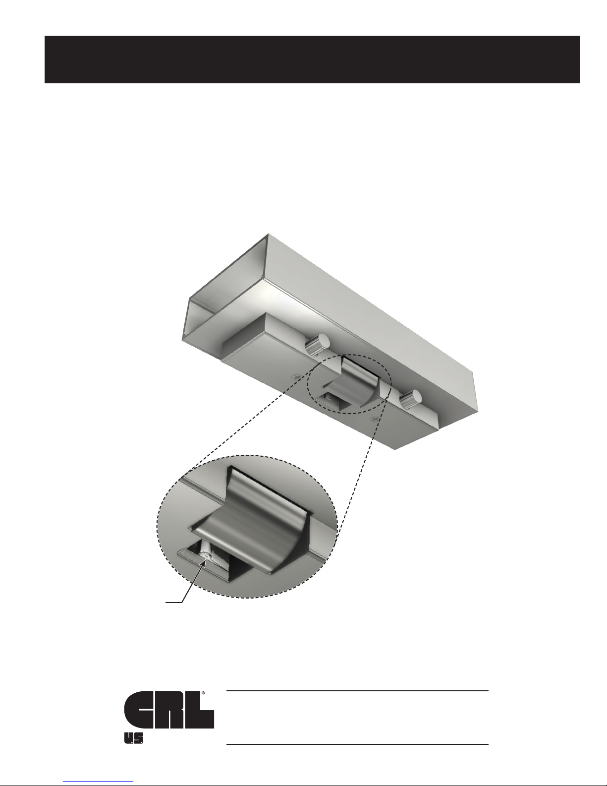
ESK1/ESP1 ELECTRIC STRIKE KEEPER
•Designed for use with 1/2" or 3/4" (12.7 or 19) tempered glass doors.
• Used in conjunction with CRL glass door Panic and Deadbolt Handles.
• Fail secure. (Fail safe optional)
• Latch/Deadbolt Monitor (ESP Strikes only)
This Electric Strike Keeper satises the following safety standards:
a. American National Standards Institute (ANSI/BHMA)
i. A117.1 Providing Accessibility and Usability for Physically Handicapped People
ii. A156.3 Exit Devices
iii. A156.18 Materials and Finishes
b. Americans with Disabilities Act (A.D.A.)
c. American Society for Testing and Materials (ASTM)
d. National Fire Protection Association (NFPA 101)
e. Underwriters Laboratory (UL)
i. 305 Panic Hardware
Tools Required
Drill bits: 1/4"
Taps: 5/16-18
Tape Measure
Saw Horses
Cordless Drill
Phillips Head Screwdriver
1/4" and 3/16" Hex Keys
3/4" Masking Tape
Center Punch
Flat Metal File
Round Metal File
Jigsaw with Metal Cutting Blade
Stepladder
Framing Square/Straight Edge
ESP040 Adjustable Gauge (Ordered Separately)
FEATURES
NOTE: Any modications, other than those specied in this document, could result in this product's failure
to meet UL safety ratings and void the manufacturer's warranties.