CROWN INDUSTRIAL 1295 User manual
C
ROW
N
INDUSTRIAL
OPE
RAT
a R S
GENERAL
OPERATOR
WIRING
AND
CONTROL
INFORMATION
1295
SLIDING
GATE
OPERATORS
Copyright
©
Crown
Indus1rial
Operators
2000
Crown
Industrial
Operators
(formerly
manufactured
by
Richards-Wilcox)
213
Michelle
Court
So.
Son
Francisco,
CA
94080
phone:
(650)
952·5150
fox:
(650)
873-1495
website:
www.crown-industriol.com
G-992-R2
CONTENTS
PAGE
INTRODUCTION
AND
GENERAL NOTES 3
OPERATOR & REVERSING STARTER WIRING
460
Volts
-
60
Hz - 3 Phase
230
Volts
-
60
Hz - 3 Phase
230
Volts
-
60
Hz - 1 Phase
115
Volts
-
60
Hz - 1 Phase
4
5
6
7 '-..---"
CONTROL WIRING
"Open"
-
"Close"
Pushbutton
Control
.
"Open"
-
"Stop"
-
"Close"
Pushbutton
Control
Momentary
Impulse
-
Timer
Control
.
Momentary
Impulse
-
Sequence
Relay
Control
8
9
10
10
NOTE: We reserve
the
right
to
modify
or
change,
without
prior
notice,
any
statements
or
information
contained
herein. If
exact
dimensions
or
specifications
are
required
by
the
customer
certified
prints
will
be
furnished
without
charge
upon
request
to
Crown
Industrial
Operators.
This
manual
covers
standard
catalogued
operators
only
and
does
not
cover
special
non-standard
equipment.
Crown
Industrial Operators, So. San Francisco, CA
G-992-R2
(650)952-5150
• Fax:
650)873-1495
2

Introduction
The
Crown
Industrial
No.
1295
Electric
Gate
Operator
is
supplied
with
the
internal
wiring
of
the
electrical
components
completed
at
the
factory.
Terminal
strip
provision
is
supplied
for
site
wiring
of
the
operator
to
external
power
supply
and
control
system.
The
factory
wiring
provides
for
ease
in site
applying
a
number
of
different
control
systems
to
the
operator
by
variations
in
terminal
connections
and
bridging.
The
purpose
of
this
booklet
is
to
provide
wiring
diagrams
and
instructions
for
the
most
popular
of
the Gate
Operator
Control
Systems.
It is
to
be
used
in
connection
with
the
Installation
Manual
(G-991)
supplied
with
each
operator.
General
Notes
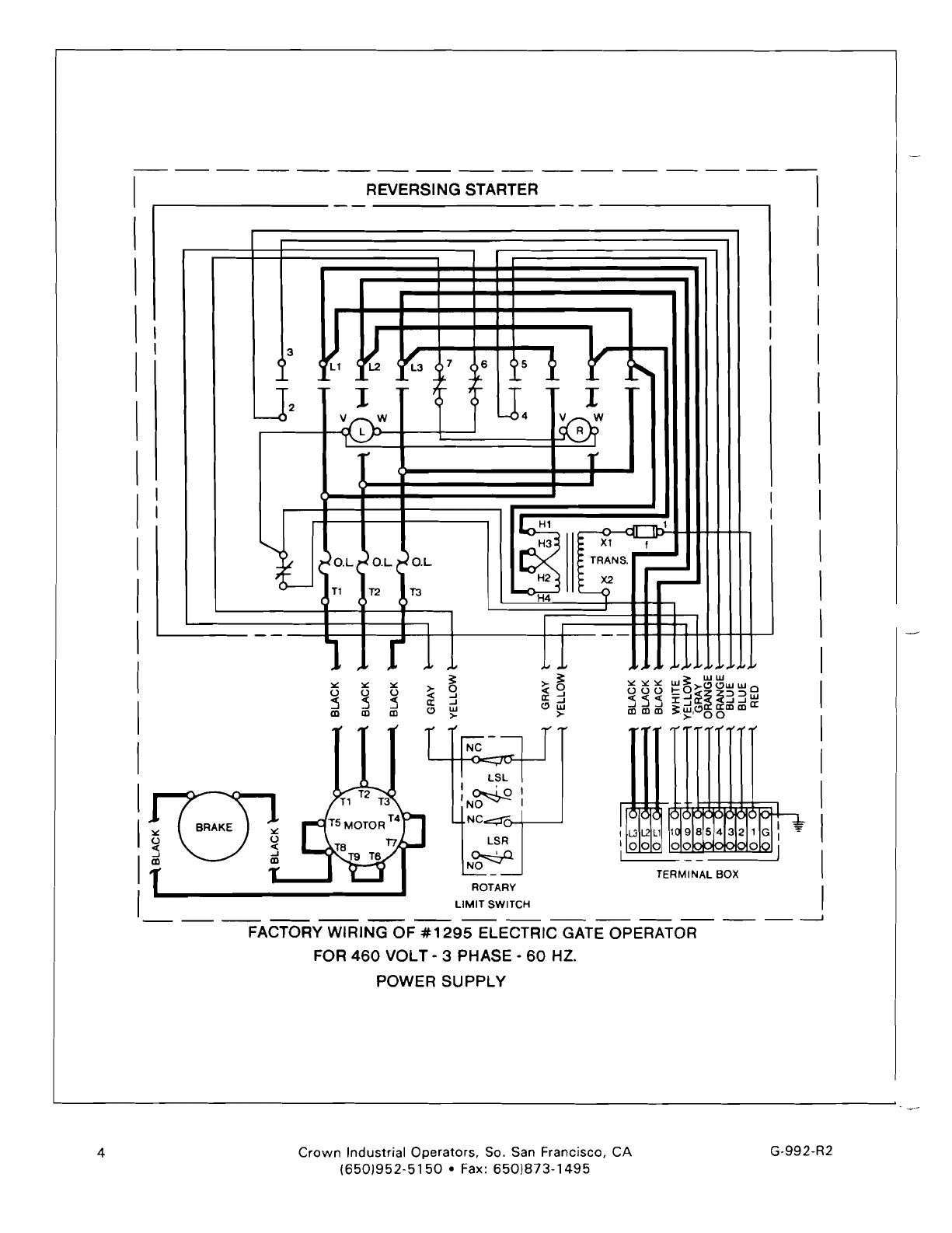
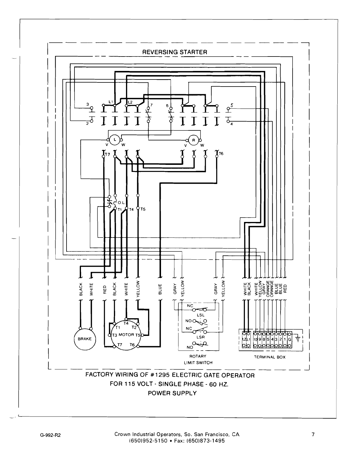
Wiring
diagrams
have been prepared to
illustrate
conditions
with
the
gate
in
the
fully
closed
position.
On
the
wiring
diagrams
of
the
Operator
Assemblies
i.e. pages 4, 5, 6 and 7
heavy
weight
lines have been used
to
denote
the
internal
power
wiring
and
lighter
weight
lines
for
internal
control
wiring.
On the
diagrams
of
"Control
Systems"
i.e. pages
8,9,
10
and 11
heavy
weight
lines
have
been used to
show
site
Wiring and
lighter
weight
lines
to
denote
factory
wiring.
In
the
control
diagrams,
control
circuits
transformers
are
shown.
(Control
circuit
transformers
are
not
provided
With
operators
intended
for
use on
115
volt
power
supplies.)
Terminal
connection
numbers
for
control
wiring
are
always
retained.
See general
installation
Instructions
manual
(G-991)
for
establishing
proper
direction
of
gate
travel.
WARI\JING
The
operator
is
pre-wired
and
tested
at
the
factory
for
a
specific
voltage
and is
marked
as
such.
Check
to
insure
that
your
power
source
is
the
same as
shown
on
the
packing
list
from
the
packing
list
envelope.
Bring
power
and
control
leads
to
the
operator
and
connect
to
the
proper
numbered
terminals
in
the
operator
terminal
box.
WARI\JING
BE SURE
ALL
POWER IS
ALWAYS
OFF WHILE WIRING OR SERVICING OPERATOR. UPON
APPLYING POWER,
SOME
ELECTRICAL
GATE
OPERATOR
CONTROL
CIRCUITS
CAN
CAUSE
IMMEDIATE
GATE OPERATION. INSURE
THAT
THE
PATH
OF THE
GATE
IS FREE FROM
OBSTRUCTIONS
AND
PERSONNEL BEFORE TURNING POWER
ON.
BRAKE
MOTOR
-----.
L ..
+111----
REVERSING
STARTER
-EPr.'INA~
BOX
Figure 1.
1295
Slide Gate
Operator
s
...
:
....
- :""':
...
:
s::=.--
::.e-
...
...
e2~-e~
~es
G-992-R2
Crown
Industrial
Operators,
So. San
Francisco,
CA
(650)952-5150
• Fax:
(650)873·
1
495
3
--
I
I
I
I I
3
o
~1
I J2 v
I
I
I
~)
)
;;~
(O.L
(
I
I
()---
T1 T2 T3
I r 1v
1
REVERSING
STARTER
I
~
I
~3
i r
7 6
>5
~
~
ll-
l..
J
1r-
1'-
114
I
)
W
lS0?
T0
r
I I
I
~
~
1
) H3 Xl I
O.L t' O.L TRANS. ......-
H2 X2 -
~
H4
--
.1
Jl
I >-
~
<0
a: ...J
Clul
I >-
I
LSL
I I .
'N~
I
NC..::::;::rcH------'
LSR
N~
I ROTARY
I
__
--J
FACTORY
WIRING
OF
#1295
ELECTRIC GATE OPERATOR
FOR
460
VOLT·
3
PHASE·
60
HZ.
POWER
SU
PPL
Y
LIMIT
SWITCH
Crown
Industrial Operators, So. San Francisco, CA G-992-R2
(6501952-5150
• Fax:
650)873-1495
4

REVERSING STARTER
I
I
~
I
I 3
ilL
1
~3
( 5 i v
7 6
~
l<-
~
lj2
I 1
.....
114
J
6
v W
lS0?
~
r•
I I
I I
~
1
<, H3
Xl
f
~
12OL.
~OL
) TRANS.
~
01.. H2 X2 ....-
)--
~
T1 T2 T3
'H4
-
TERMINAL BOX
L..
L.<
>-
~
« 0
II: j
Cl UJ
>-
~
v II
~
>-
~
o
~
...J
~
o
u1
l'
~
I'
INC
--=:l
I
JL
I
I r I
IN~I
!'l~H-_---l
LSR
~
~--
_T61
T4
TVI
'i..J'
~~
(.) (.)
:5
:5
al al
T
ROTARY
LIMIT
SWITCH
--
--
--
--
--
--
----
-- --
--
--
--
__
---I
FACTORY WIRING OF
#1295
ELECTRIC GATE OPERATOR
FOR
208
OR
230
VOLT
- 3 PHASE -
60
HZ.
POWER
SUPPLY
G-992-R2
Crown
Industrial Operators, So, San Francisco, CA
(650)952-5150
• Fax:
(6501873-1495
5

I--
I
I
I
I
I
I
I
I
REVERSING STARTER
3
L1~~~
7 6 d
1""
1
-i'
.L
_,-
_ _ _
~
-
~-
r-
ITT
I (
~
-r TTTT
IT
2-
( 4
~
~W
(17
[\(
~
T6 T
~
,
I •
I
.;~(
O.L
H4 1
,--
H),-
~
Tl,-
T4 T5
~
Xl f
TRANS. -
TX2
r---
1-'1
--
-
r-'
-
f-
1,L
I.-
, , ~,
I
I
I
I
~
UJUJ
~ ~
:.: UJ :.:
UJ
~
UJ UJ:':
>- >- >- :':' o>-<:J<:JUJUJ 0
0 o 0 0 a >-.u
U t:
UJ
-c t: ..J
::::>
-c -c ..J -c ..J
-«
-..J«zZ::::>::::>UJ
:I: :I: ..J ..J a: a: ..J a: ..J
:I:..J
:5
a: ..J UJ
CD
<:J <:J
UJ
<:J
loU
~CD
~
u:l~~i'h:liIl
a:
CD
~
CD
~
>- >- >- >-
00
LSL
NO~
I NC
~'~"
NO~
TERMINAL
BOX
G-992-R2
Crown
Industrial Operators, So. San Francisco, CA
(650)952-5150
• Fax:
6501873-
1495
6
---
-----
---,
REVERSING STARTER
3 L1 J L2
~
-i. r
_L'Y
~
T
2
TTl
1
~
Ij
(17
-, , r\.
I
'!-
OL
~
H~'
T5
I
T11
T4
--
7 6
L.
~L.
-~
~
~
_5
L.
..I.-
TIlT
T 4
~
V W
{ "
T6
~
~
poo--
-
l-
,(,
,
>-
3:
...:
0
a: j
c:>
UJ
>-
I
I
I
I
>-
~
...:
-'
a:
-'
c:>
UJ
>-
NC
LSL
NO~
I NC
I
'--......£:JTT)----..--'
L~R
I
NO~
~--
ROTARY
LIMIT
SWITCH
_
TERMINAL
BOX
I
I
I
I
I
I
I
I
I
I
I
I
I
I
I
I
I
I
I
I
I
I
I
I
--.J
FACTORY WIRING OF #
1295
ELECTRIC GATE OPERATOR
FOR 115 VOLT - SINGLE PHASE - 60 HZ.
POWER SUPPLY
G-992-R2
Crown
Industrial Operators, So. San Francisco, CA
(650)952-5150
• Fax:
(650)873-1495
L
7
"L3"
- THREE PHASE OPERATOR
APPLICATIONS ONLY TERMINAL STRIP
PUSHBUTTON
STATION
SITEWIRING
Xl
TRANS. X2
115
Volt
O.L.
OPEN
....
..
~-J..-._
..
LSR(N.C.1
9 w
CLOSE
~
Jj~e-
_
8 LSLlN.C.1 6 R
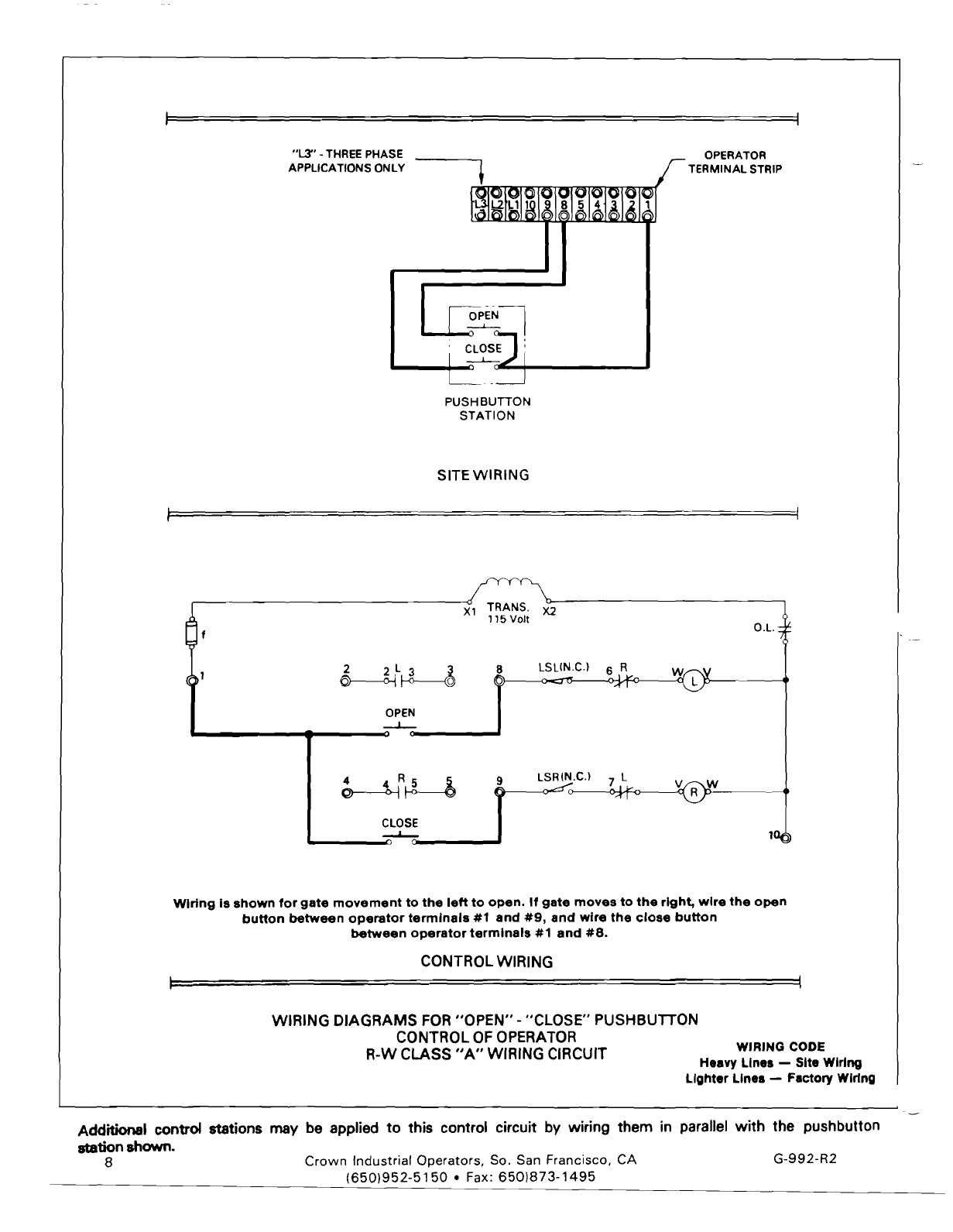
WIring
Is
shown
for
gate
movement
to
the
left
to
open.
If
gate
moves
to
the
right,
wire
the
open
button
between
operator
terminals
#1
and
#9,
and
wire
the
close
button
between
operator
terminals
#1
and
#8.
CONTROL WIRING
WIRING DIAGRAMS FOR
"OPEN"
-"CLOSE" PUSHBUTTON
CONTROL OFOPERATOR WIRING CODE
R-W CLASS
"A"
WIRING CIRCUIT Heavy
Line.
- Site Wiring
Lighter
Line.
-Factory WIring
Additional control stations may be applied to this control circuit by wiring them in parallel
with
the pushbutton
stationshown. Crown Industrial Operators, So. San Francisco, CA G-992-R2
(650)952-5150
• Fax:
6501873-1495
8

"l..3"
•THREEPHASE OPERATOR
APPUCATIONS ONLY
-.
TERMINAL STRIP
1L3~L2U]
I
!!!I
III
d
4-1
~II
~I
--.:;.
IOPEN~
I
___
,..
I
CLOS:..I
i
I STOP
......
Ii
L--
__ -----l
PUSHBUTTON
STATION
SITEWIRING
TRANS.
115 Volt
Xl X2 O.L
STOP 22t 3 B LSLIN.C.1
OPEN
--L-
4 4 R 5 5
CLOSE
~
LSRIN.C.1 7 L V R
10
WIring
Is
shown
for
gate
movement
to
the
left
to
open.
If
gate
opens
to
the
right,
wire
the
open
button
between
operator
terminals
#2
and
#9,
and
the
close
button
between
operator
terminals
#2
and
#8.
CONTROLWIRING
WIRING DIAGRAMS FOR"OPEN".- "CLOSE" - "STOP" PUSHBUTTON
CONTROLOF
OPERATOR
WIRING
CODE
R-W CLASS
"B"
WIRING CIRCUIT H
••
vy Linea -
Sit.
WIring
Lighter Lines -
F.ctory
Wlrtng
Additional control stations maybeappliedto this control circuit by wiring the
"Stop"
contacts of all stations in serieswith
the
"Stop"
pushbutton shown. Wire
"Open"
and "Close" contacts in parallelwith
"Open"
and "Close" push button
shown. Note that
A1I.
"Stop
contacts" must be wired in series in the wire from terminal number 1 prior to supplying
"Open"or "Close"contacts. Crown Industrial Operators, So. San Francisco, CA
(650)952-5150
• Fax:
(6501873-1495
G-992-R2 9
IL~IL2IL;11019
815.14131211
r-.
(@i
,
,
I I
r----oPEN\
--L.-
,
;
le:1
Ie
'C§I
I~
'---~
04 1 air :
I
91c
rl
o~
PUSHBUTTON
STATION
,
"L3".
THREEPHASE OPERATOR
APPLICATIONS ONLY TERMINAL STRIP
+
TIMER SITEWIRING
X2
O.L
6 T
3 T
OPEN
~
.....
_.....0
.-
T.
SOL
__
...
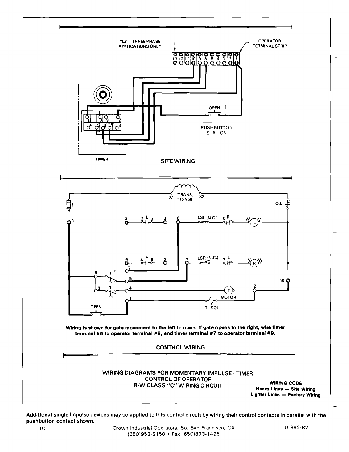
WIring
Is
shown
for
gate
movement
to
the
left
to
open.
If
gate
opens
to
the
right,
wire
timer
terminal
#5
to
operator
terminal
#8,
and
timer
terminal
#7
to
operator
terminal
#9.
CONTROL WIRING
9 LSR (N.C.) 7 L W
R
5 10
4
WIRING
DIAGRAMS
FOR MOMENTARY IMPULSE - TIMER
CONTROL OF OPERATOR WIRING CODe
R-W CLASS
"C"
WIRING CIRCUIT Heayy Lines - Site WIring
Lighter Lines - Factory WIring
Additional single Impulse devices may be applied to
this
control circuit by wiring their control contacts in parallel with the
pushbutton
contact
shown.
Crown
Industrial Operators, So. San Francisco, CA
G-992-R2
(6501952-5150
• Fax:
650)873-1495
10

----
SEQUENCERELAY
PUSHBunON
STATION
SITEWIRING
OPERATOR
TEkMINAl
STRIP
"L3"
- THREEPHASE
APPLICATIONS ONLY
r-P.BI
,
--!-
.b---+---------+-::
0-""1"'---
C
L...._
......
TRANS.
115
Volt
Xl X2
e(t
O.l.
t
1
8
lSLlN.C.l
6 R
~
1
~l~~
(
.J-~--
l
4 4 R 5 5
lS~~_
@-------<''-1
f--O-----©
SR N.C.H.O.
-,..,
T
S~
N.C.H.C.
10~~
·~"B.
SR
CONTROL WIRING
WIRING
DIAGRAMS
FOR
MOMENTARY
IMPULSE - SEQUENCERELAY
CONTROL OFOPERATOR WIRING CODE
R-W CLASS
"0"
WIRING CIRCUIT Heavy Lines - Site Wiring
Lighter Lines -
Factory
Wiring
Additional single impulse devices may be applied to
this
control
circuit
by wiring their control
contacts
in parallel
with
the
pushbutton
contact
shown.
G-992-R2
Crown
Industrial Operators, So. San Francisco, CA
(650)952-5150.
Fax:
(650)873-1495
11
MAINTENANCE
INFORMATION
(To
Be
Filled
Out
By
User)
Operator
Serial
Number
1295-
__
Supplied
on
(10
Order
Number
Power
Supply
Installed
At:
\lJlts
Hz
Dote:
Hp
Phase
_
_
_
Notes:
_
GUARANTEE
If,
within
a
period
of
one
year
from
dote
of
shipment,
any
port
ofa
ao
£Ied,;c
'Aut~oR'
Operator
is
found
defective
due
to
poor
materials
or
workmanship,
new
ports
will
be
furnished
free
of
charge
fO.B.
manufacturer's
plant,
providing
the
equipment
has
been
given
normal
and
proper
usage,
lubrication,
and
maintenance
and
is
still
the
property
of
the
original
purchaser
and/or
port
of
the
original
installation.
THIS
WARRANTY
IS
GIVEN
IN
LIEU
OF
All
OTHER
WARRAN·
TIES,
EXPRESS
OR
IMPLIED,
AND
THE
MANUFACTURER
MAKES
NO
IMPLIED
WARRANTY
OF
MERCHANTABILITY
BEYOND
THE
EXPRESS
TERMS
HEREOF.
MANUFACTURES'S
lIABIl1TY
FOR
DAMAGES,
INCLUDING
CONSEOUENTlAl
DAMAGES,
RESULTING
FROM
ANY
SUCH
DEFECTIVE
PRODUCT
IS
STRICTlY
LIMITED
TO
THE
DElIVERY
OF
NEW
PARTS,
AS
SET
FORTH
ABOVE.
----~---~-----1::J·····
lEc--
__
-_
-_~
--~
=========
213
Michelle
Court
c • 0 W III
South
San
Francisco,
CA
94080
INDUI'.IAI.
OPE
A
AT
0 A S
Phone
(650)
952-5150
Fax
(650)873-1495
Table of contents
Other CROWN INDUSTRIAL Gate Opener manuals


