CROWN INDUSTRIAL AUT-O-DOR 1510 User manual

G-993-R3
Crown Industrial Operators
(Formerly manufactured by Richards-Wilcox)
213 Michelle Court
So. San Francisco, CA 94080
Phone (650) 952-5150
Fax (650) 873-1495
website: www.crown-industrial.com
Copyright © Crown Industrial Operators 2011
GENERAL
INSTALLATION,
OPERATION,
MAINTENANCE,
and PARTS MANUAL
for your
1510 SWING-GATE
OPERATOR MODEL "F"
HEAVY DUTY & EXTRA HEAVY DUTY
CROWN
NDUSTRAI IL
OPERATORS

CONTENTS
PARAGRAPH PAGE
1 INTRODUCTION............................................................................... 1
A Purpose......................................................................................... 1
B Models Covered............................................................................ 1
C Application..................................................................................... 1
D Description.................................................................................... 1
2 INSTALLATION AND OPERATION................................................... 1
A General ......................................................................................... 1
B Preparing The Mounting Channel................................................. 2
C Mounting the Operator.................................................................. 2
D Mounting the Arms........................................................................ 2
E Wiring the Operator....................................................................... 6
F Phasing Out Motor........................................................................ 6
G Adapting Controls.......................................................................... 7
H Preliminary Limit Switch Adjustment ............................................. 7
I Setting the Clutch.......................................................................... 7
J Final Limit Switch Adjustment ....................................................... 7
3 MAINTENANCE ................................................................................ 8
A General ......................................................................................... 8
B Lubrication..................................................................................... 8
C Preventative maintenance............................................................. 8
4 PARTS............................................................................................... 9
A To Order Replacement Parts......................................................... 9
B Parts List....................................................................................... 9
Parts List-Heavy Duty 1/2, 3/4, 1 HP Operator............................. 10
Parts List-Extra Heavy Duty 1 HP Operator.................................. 12
WARRANTY...................................................................................... 14
Note: We reserve the right to modify or change, without prior notice,
any statements or information contained herein. If exact dimensions
or specifications are required by the customer certified prints will
be furnished without charge upon request to Crown Industrial. This
manual covers standard catalogued operators only and does not cover
special non-standard equipment.
Crown Industrial Operators • 213 Michelle Ct. • So. San Francisco, Ca 94080-6202
Phone: (650) 952-5150 • Fax: (650) 873-1495

1. GENERAL INTRODUCTION
A. PURPOSE: This Crown Installation, Operation,
Maintenance and Parts Manual has been developed to
assist you in the installation, operation and maintenance
of your electric operator and thus enable you to utilize it
to its maximum efficiency.
B. MODELS COVERED: The manual covers the
Model 1510 Operator in production and contains the
latest information available. The parts pages have been
prepared so that you can easily determine the parts
contained in your Electric Operator.
C. DESCRIPTION:
(1) GENERAL: The Heavy Duty Operator is built into a
compact unit consisting of an instantly reversing motor, a
precision made speed reduction mechanism with V-belt
and pulleys, a safety friction disc clutch, an emergency
release, a fully automatic double acting limit switch, a
heavy duty crank and connecting arm assembly, and
a weather resistant cover (Figure 1). The Extra Heavy
Duty Operator is similar but without the V-belt and
pulleys.
(2) MOTORS: The motor has ample reserve power to
take occasional overloads, and is furnished in 1/2, 3/4,
or 1 HP sizes for standard gates, and a 1 HP (gearhead
motor) for extra large and heavy gates. Motors are
available in single phase, however three phase current is
highly recommended for best all around performance.
(3) SHAFTS AND GEARS: Shafts and gears in the
heavy unit are mounted in long life bearings enclosed
in an oil tight housing and operate at all times in a bath
of grease (extra heavy duty units are oil filled). The
automatic limit switch is built on the reduction unit and
stops the gate in the desired open or closed position.
(4) CRANK AND CONNECTING ARMS: The operating
levers consist of a heavy duty crank and connecting
arms. The crank arm is driven by a safety friction disc
clutch which protects equipment in case the gate comes
in contact with an obstruction. A disconnecting device is
provided to allow manual operation.
2. INSTALLATION AND OPERATION
A. GENERAL
The Crown Industrial 1510 Electric Gate Operator is
rugged, well designed, dependable, and field proven
to be trouble free for swing gates. To ensure correct
installation and proper operation, observe the following
instructions:
(1) CHECK THE SHIPMENT: Included with the
installation packet is a copy of the material specification
sheet for the components supplied with the order.
Compare the components received with the material
specification sheets to insure that all equipment is
complete.
Figure 1.
1510 Heavy Duty Swing Gate Operator.
(Shown with weather-resistant cover removed)
Figure 2. Swing Gate
RIGHT HAND SWING
LEFT HAND SWING
Crown Industrial Operators • 213 Michelle Ct. • So. San Francisco, Ca 94080-6202
Phone: (650) 952-5150 • Fax: (650) 873-1495

(3) CHECK THE GATES: Before starting Operator
installation, inspect to ensure that the gates are in good
working condition, are rigidly supported, and have no
obstructions to block or retard their swing. Electric Gate
Operators cannot be expected to power operate gates
where conditions prevent or resist manual operation.
Latches, foot bolts, or other devices should be removed
from the gate to prevent their accidental engagement.
When standing in a position facing the closed gate and
the gate swings toward you to open, the gate has its
pivot pin to the left, this is considered a left hand. When
the gate has its pivot pin on the right and opens toward
you, it is considered right hand. Refer to Figure 2 Swing
Gate for gate handing.
(4) REVIEW THE INSTALLATION DRAWINGS: The
installation drawings show the layout of the gate,
template drilling for the gate bracket and channel post,
and general terms used to describe components.
Review of the installation drawings will familiarize you
with the equipment.
(5) PREPARING THE GATE: The Electric Gate
Operator powers the gate through a gate bracket
attached to an intermediate cross rail of the gate. If the
gate is not provided with a cross rail, a 2-1/2"x 2-1/2"
x 3/8" or larger structural angle can be installed, leg
up, across the gate to receive the gate bracket. The
cross rail is prepared for the gate bracket by drilling two
mounting holes on the horizontal center line of the cross
rail. These holes are located from the center line of the
gate pivot or hinge pin - see Figure 3, 4, 5, or 6.
B. PREPARING THE MOUNTING CHANNEL
(1) CONCRETE EMBEDDED TYPE:
(a) The channel post for support of the Operator is
an optional extra cost item. When furnished as an
optional part of the operator equipment, they will be pre-
drilled for the mounting of the Operator and hot dipped
galvanized. When the channel posts are not provided,
posts of the size indicated on Figure 3 or 4 are required.
These posts should be drilled in accordance with the
channel post drilling template on Figure 3 or 4. It is
recommended that the posts be hot dipped galvanized
or specially treated to avoid corrosion. The channel post
should be set to dimensions shown on Figure 3 or 4 in
concrete piers, considering the angle of the gate in the
full open position. The size and depth of the piers may
vary with soil and fill types.
NOTE: The customer and/or contractor is
responsible for the proper installation of the
mounting posts. The posts must be installed plumb
and in exact position as shown on Figure 3 or 4.
(b) The top of the channel post should be positioned
vertically one inch below the horizontal center line of the
gate bracket mounting holes drilled in the gate cross rail.
The back of the channel post web should be located
parallel to, and three and one-half inches away from the
gate frame in the gate’s fully opened position (regardless
of degree of opening).
(c) Locate the inside edge of the channel post flange
(Dim. "E") from the center line of the gate pivot and
along the line of the opened gate as indicated on Figure
3 or 4.
(2) PAD MOUNTED TYPE: The type mounted channel
for support of the Operator is available as an optional
extra cost item. When furnished, they will be pre-drilled
for mounting of the Operator and to the concrete pad.
NOTE: A suitable mounting pad with (4 ea.) 3/4"
diameter studs is the responsibility of the customer
and/or contractor. The pad must be level and the
studs in the exact position as shown on Figure 5.
C. MOUNTING THE OPERATOR
(1) Remove the Electric Gate Operator from the crate.
The Gate Operators are universal and therefore can be
used on either hand gate. (Heavy Duty Units Only).
NOTE: The extra heavy duty operators are handed.
(2) Remove the front cover of the Operator by removing
the self-tapping screws from the edges of the cover and
sliding the front cover down, then away.
(3) Remove the nuts, lock washers, and flat washers
from the bolts on the back of the Operator. Raise the
Operator into position on the channel post, inserting
the mounting bolts. Secure the Operator with the flat
washers, lock washers, and nuts.
D. MOUNTING THE ARMS
(1) Release the arm plate by pulling down on the clutch
release chain located on the side of the Operator. To
keep the arm plate disengaged, insert a wedge of some
sort between the clutch yoke the chain is connected to
and the bottom of the clutch. Check to see if the arm
plate is free to rotate. (See Figure 7).
Crown Industrial Operators • 213 Michelle Ct. • So. San Francisco, Ca 94080-6202
Phone: (650) 952-5150 • Fax: (650) 873-1495
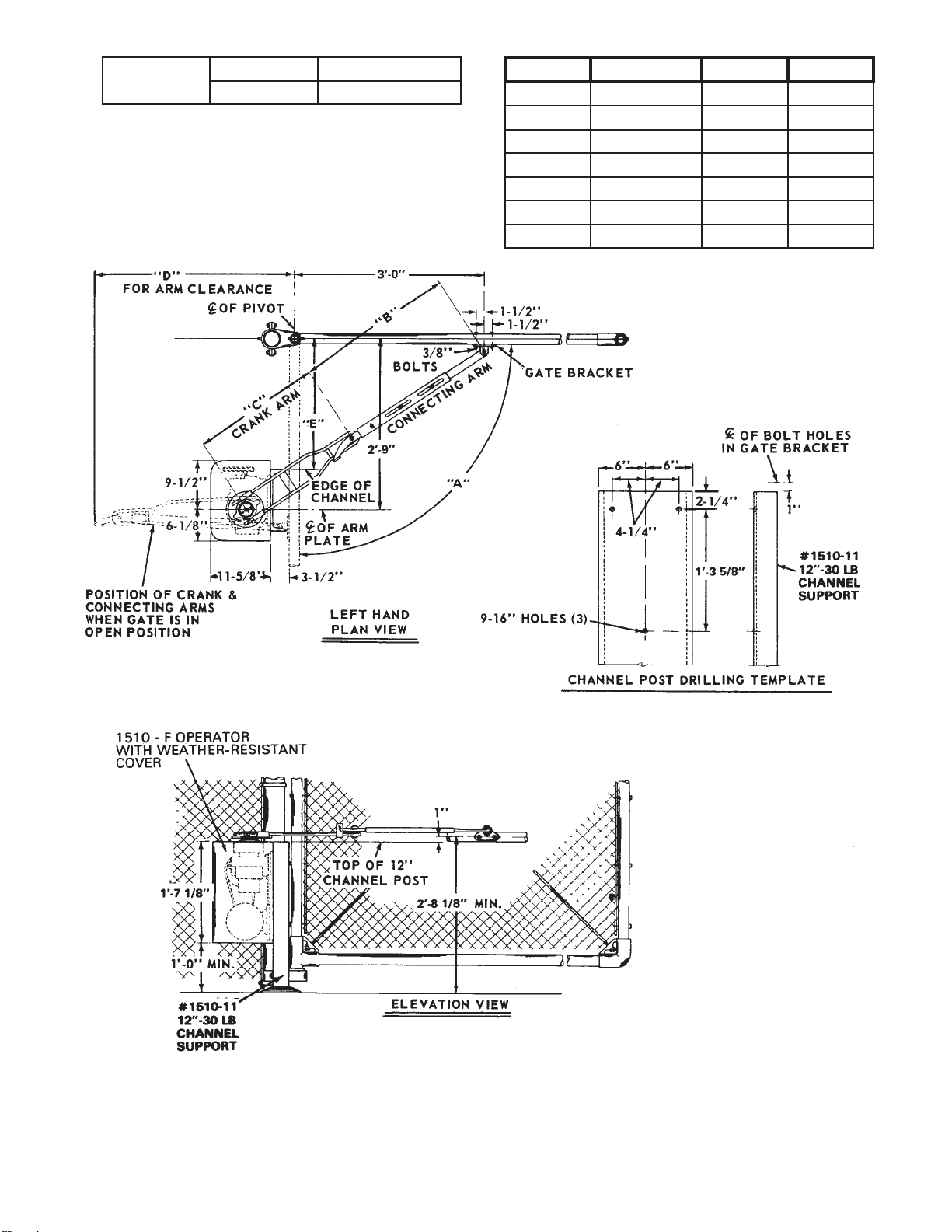
Figure 3. Installation of Operator - Heavy Duty 1/2, 3/4, and 1 H.P.
(Using Concrete Embedded Mounting Channel)
E2’ - 1-1/4" LEFT HAND
2’ - 4-3/4" RIGHT HAND ABCD
90° 2’ - 6-1/4" 2’ - 0" 3’ - 2"
95° 2’ - 7 1/4" 2’ - 1" 3’ - 6"
100° 2’ - 8" 2’ - 2" 3’ - 10"
105° 2’ - 8-3/4" 2’ - 2-3/4" 4’ - 1"
110° 2’ - 9-3/4" 2’ - 3-1/2" 4’ - 4"
115° 2’ - 10 1/4" 2’ - 4 1/4" 4’ - 8"
120° 2’ - 11" 2’ - 4-3/4" 4’ - 11"
Crown Industrial Operators • 213 Michelle Ct. • So. San Francisco, Ca 94080-6202
Phone: (650) 952-5150 • Fax: (650) 873-1495
G-993-R3 3

Figure 4. Installation of Operator - Extra Heavy Duty 1 H.P.
ABCD
90° 2’ - 10-1/2" 2’ - 2-1/4" 3’ - 6"
95° 2’ - 11-5/8" 2’ - 3-7/8" 3’ - 7-1/8"
100° 3’ - 0-1/4" 2’ - 4-1/4" 3’ - 7-3/4"
105° 3’ - 1-3/8" 2’ - 5-1/8" 3’ - 8-7/8"
110° 3’ - 2-1/4" 2’ - 6-1/8" 3’ - 9-3/4"
115° 3’ - 3" 2’ - 6 7/8" 3’ - 10-1/2"
120° 3’ - 3-5/8" 2’ - 7-1/2" 3’ - 11-1/8"
1' - 8"
2' - 3"
8 1/2"
1'-10"
1'- 5"
1'- 3"
14"
Crown Industrial Operators • 213 Michelle Ct. • So. San Francisco, Ca 94080-6202
Phone: (650) 952-5150 • Fax: (650) 873-1495

Figure 5. Installation of Operator - Heavy Duty 1/2, 3/4, and 1 H.P.
(Using Pad Mounted Column)
ABCD
90° 2’ - 6-1/4" 2’ - 0" 3’ - 2"
95° 2’ - 7-1/4" 2’ - 1" 3’ - 6"
100° 2’ - 8" 2’ - 2" 3’ - 10"
105° 2’ - 8-3/4" 2’ - 2-3/4" 4’ - 1"
110° 2’ - 9-3/4" 2’ - 3-1/2" 4’ - 4"
115° 2’ - 10-1/4" 2’ - 4-1/4" 4’ - 8"
120° 2’ - 11" 2’ - 4 3/4" 4’ - 11"
Crown Industrial Operators • 213 Michelle Ct. • So. San Francisco, Ca 94080-6202
Phone: (650) 952-5150 • Fax: (650) 873-1495

(2) Mount the crank arm in place by inserting the rod
ends into the two holes at the edge of the arm plate on
top of the Operator. Be sure the pivot stud at the end of
the arm is pointing up. By sliding the arm into or out of
the arm plate holes, you can adjust the distance between
the center point of the arm plate to the pivot stud to
dimension "C" shown on Figure 3, 4, or 5. Tighten the
two set screws securely on each side of the arm plate to
secure the crank arm into the arm plate.
(3) Loosen the adjusting bolts on the connecting arm.
Remove the nut and washer from the crank arm pivot
stud and install the hooked end of the connecting arm
to the crank arm. Note that the extended hooked end
over-travel stop on the connecting arm should fall on
the side of the crank arm away from the gate pivot. The
gate bracket on the far end of the connecting arm should
then be attached to the gate cross rail with the 3/8" bolts
provided. (See Figure 3, 4, or 5).
(4) With the gate closed, the arms should then be
placed in a position so that the center point of the crank
arm pivot stud falls on a direct line between the center
point of the arm plate and the center point of the gate
bracket. With this accomplished, the adjustment bolts on
the connecting arm should be tightened.
(5) The gate should then be opened, with the clutch
disengaged, by manually breaking the dead center
condition of the crank arm and connecting arm away
from the gate pivot and then manually swinging the gate
open.
WARNING: After breaking the dead center position
of the arms, do not attempt to open the gate with
operator arms. Hands can be pinched between the
crank and connecting arms as the gate reaches the
open position.
(6) When the gate is fully open, the arms should
assume the position shown by the dotted lines in Figure
3, 4, or 5. If the arms reach a locking position before
the gate is fully open, a re-adjustment of the arms is
required.
E. WIRING THE OPERATOR
(1) Wire the Operator and control circuit as shown
onokay the wiring diagram enclosed, "General Operator
Wiring and Control Information Manual". BE SURE ALL
POWER IS OFF.
F. PHASING OUT MOTOR
(1) Remove the weather plate, gasket, and retaining
ring from the arm plate and lift the arm plate from the
operator. Remove the wedge from the clutch.
(2) THREE PHASE: Turn power on. Using the left side
reversing contactor for counter-clockwise rotation, and
the right side contactor for clockwise rotation, press
one of the control buttons. Note the direction the top of
the operator is rotating. For a pair operation, operators
should be tested separately. If the top is rotating counter-
clockwise, then the left side contactor coil should be
energized. If the wrong coil happens to be energized, for
the counter-clockwise direction, exchange any to power
leads.
(3) SINGLE PHASE: The operator and reversing starter
are factory prepared for proper rotation.
(4) Check both directions several times to ensure proper
phasing of motors. In case the motor continues to run at
end of travel and the limit switch does not stop rotation,
check the limit switch function and review the proper
control circuit wiring.
SNAP ACTION
SWITCHES
PINION
SWITCH CAM
PULL OUTWARD,
AWAY FROM CENTER
AND ROTATE TO
ADJUST TIMING Figure 6. Adjusting Limit Switch
Crown Industrial Operators • 213 Michelle Ct. • So. San Francisco, Ca 94080-6202
Phone: (650) 952-5150 • Fax: (650) 873-1495

G. ADAPTING CONTROLS
(1) Using the left side contactor for counter-clockwise
rotation of the top of the operator, determine if this
rotation sends an open or close signal to the left side
contactor. On pair operated gates, one operator is to
be wired as described, and the second operator is
wired using the opposite reversing starter coils. I.E. If
less contactor coil opens the right-hand gate, the right
contactor coil will open the left-hand gate.
H. PRELIMINARY LIMIT SWITCH ADJUSTMENT
(1) Loosen the four clutch tension bolts and then set the
arm plate back into place on the clutch. Do not replace
any other items at this time.
(2) To adjust the limit switch, (Figure 6), manually open
the gate to within 6 inches of its fully open position, at
the same time allowing the clutch to slip. At this point,
determine which snap action switch would shut the
operator off. Pull outward on the cam in line with that
switch and rotate it toward the switch and over it just
far enough to shut the operator off. The cam must be
rotated in the same direction as the crank arm is rotated
to open the gate. The cam should also be reengaged
with the center pinion at this point.
(3) Manually close the gate to within 6 inches of its
fully closed position. Pull outward on the other cam and
rotated toward an slightly over the other snap action
switch. The cam must be rotated in the same direction
as the crank arm is rotated to close the gate and must
be reengaged with the center pinion.
I. SETTING THE CLUTCH (Figure 7)
(1) Remove the arm plate and tighten down the four
clutch tension bolts evenly (see Figure 7) until the friction
is sufficient to operate the gate. Never tighten the bolts
so that the clutch cannot be slipped by forcing the end
of the crank arm, and never I just bolts consecutively,
but always directly across from each other so as to
provide even tension. An equal turn of each bolt is a very
important adjustment procedure.
WARNING!! Some electrical gate operator control
circuits can cause immediate gate operation upon
applying power. Ensure that the path of the gate
and operating arm is free from obstructions and
personnel.
(2) Replace on plate being certain the clutch pins are
engaged and electrically start the gate moving until it is
halfway between the open and closed position. Cut the
power at this point.
(3) If the gate can be manually moved from this halfway
point, readjust the clutch accordingly.
(4) After the clutch is adjusted to suit, replaced the
retaining ring, gasket, and weather plate in that order.
J. FINAL LIMIT SWITCH ADJUSTMENT
(1) With Power on, opened the gate until it stops under
its own power. If it stops short, electrically start gate
closing and cut the power. Pull outward on the opening
cycle switch camp and rotate away from the opening
cycle snap action switch one tooth on pinion gear and
reengage with center pinion. Turn power on.
(2) Close the gate until it stops under its own power. If
it stops short, electrically start gate open and cut power.
Pull outward on the closing cycle switch camp and
rotates away from the closing cycle snap action switch
one tooth on pinion gear and reengage with center
pinion. Turn power on.
(3) Continue cycling the gate and make cam
adjustments until the gate stops in the proper location.
(4) Replace the front weather resistant cover.
ARM PLATE CLUTCH TENSION
ADJUSTMENT
(FRONTAND BACK)
TOP VIEW
CLUTCH TENSION
ADJUSTMENT
(FRONTAND BACK)
Figure 7. Adjusting Clutch
Crown Industrial Operators • 213 Michelle Ct. • So. San Francisco, Ca 94080-6202
Phone: (650) 952-5150 • Fax: (650) 873-1495

3. MAINTENANCE
A. GENERAL:
To ensure that the electric operator is ready for operation
at all times, it must be inspected systematically each will
preclude serious damage or failure. Proper adjustment
and lubrication must be maintained and checked as
recommended in the following.
B. LUBRICATION
(1) Lubrication Intervals:
EVERY 6 MONTHS
1. Lubricate Pivot Points with SAE 10 Oil.
2. Check Oil Seals for Leakage.
EVERY 12 MONTHS
1. Clean Limit Switch Cam and Pinion Gear and
lubricate with SAE 10 oil.
2. Check oil level. If low, fill with lithium
complex extreme pressure grease, NLGI No. 2.
3. For Extra Heavy Duty Units (1 H.P.), check
green colored tag attached to the gearmotor.
CAUTION: Do Not Overfill. Do Not Use Machine Oil.
C. PREVENTATIVE MAINTENANCE
To prevent damage or improper operation, the following
inspections should be made at least EVERY SIX
MONTHS.
1. Check pivot points for wear.
2. Inspect drive belt for wear.
(Does not apply to Extra Heavy Duty 1 H.P. Units)
3. Inspect clutch discs for wear.
4. Check clutch for correct tension.
5. Check limit switch cams and pinion for wear.
6. Check that all bolts are tight.
Crown Industrial Operators • 213 Michelle Ct. • So. San Francisco, Ca 94080-6202
Phone: (650) 952-5150 • Fax: (650) 873-1495

3. PARTS
A. TO ORDER REPLACEMENT PARTS:
Order all replacement parts using the numbers shown on
the following parts list pages.
(1) Send in Serial Number of Electric Operator.
(2) SPECIFY the number of pieces needed.
(3) Order by part number and the name of the part.
(4) Indicate how the material should ship.
(5) State whether transportation charges are to be
prepaid or collect.
(6) Name and address of person or company to whom
invoice is to be sent.
B. PARTS LIST
The following pages list the replacement parts illustrated
in Figure 8 and 9.
Crown Industrial Operators • 213 Michelle Ct. • So. San Francisco, Ca 94080-6202
Phone: (650) 952-5150 • Fax: (650) 873-1495
G-993-R3 9

FIGURE NO. PART NUMBER DESCRIPTION
8 266-7 Washer
8 400-34 Switch Insulator (2 per operator)
8 400-95 Snap Action Switch (2 per operator)
8 1200 Motor Per Specifications
8 1200-25 Motor Mounting Bracket
8 1251-11 Motor Pulley
8 1300-57 Clutch Collar Key
8 1300-64 Clutch Shaft Bushing
8 1300-180 Handle
8 1500-7 Gear
8 1500-8 Pinion Gear
8 1500-9 Worm Gear
8 1500-10 Clutch Shaft
8 1500-13 Pinion Shaft
8 1500-14 Thrust Bearing (2 per operator)
8 1500-25 Clutch Shaft Collar
8 1500-26 Clutch Pin (2 per operator)
8 1500-27 Compression Spring (2 per operator)
8 1500-28 Pin Shift Collar
8 1500-29 Top Clutch Plate
8 1500-32 Retaining Disc
8 1500-33 Clutch Disc (2 per operator)
8 1500-34 Bearing (4 per operator)
8 1500-45 Bearing
8 1500-46 Bearing
8 1500-47 Gasket
8 1500-92 Arm Plate
8 1500-98 Worm Shaft Key
8 1500-99 Clutch Shaft Key
8 1500-100 Key
8 1500-114 Clutch Shaft Oil Seal (2 per operator)
8 1500-115 Worm Shaft Oil Seal
8 1500-116 Worm
8 1500-117 Arm Plate Cap
8 1500-118 Arm Plate Cap Gasket
8 1500-124 Pinion Shaft Key
8 1500-253 Upper Gear Housing (Incl. 1500-34 & 1500-46 Bearing)
8 1500-254 Lower Gear Housing (Incl. 1500-34 & 1500-45 Bearing)
8 1500-255 Release Yoke
8 1500-256 Clutch Bolt
8 1500-257 Bottom Clutch Plate
8 1500-258 Worm Shaft
8 1500-259 Switch Throw Pinion
8 1500-260 Switch Cam (2 per operator)
8 1500-261 Switch Cam Spring (2 per operator)
8 1500-262 Closed Eye Eyelet (2 per operator)
8 1500-263 Switch Frame
8 1500-264 Switch Cover
8 1500-265 5" P.D. Pulley (Std. Speed)
8 1500-266 8.7" P.D. Pulley (Low Speed)
8 1500-384A Clutch Assembly (Consisting of Parts: 25, 26, 27, 28, 29, 32, 33, 92, & 257)
8 1500-428 Weather Resistant Cover Front
8 1500-478 Base Plate
8 1500-481 Weather Resistant Cover Back
8 1MO28 28" 4L V Belt (used with 5" P.D. Pulley)
8 1MO35 35" 4L V Belt (used with 8.7" P.D. Pulley)
PARTS LIST -- HEAVY DUTY 1/2 3/4 - 1 HP OPERATOR
Crown Industrial Operators • 213 Michelle Ct. • So. San Francisco, Ca 94080-6202
Phone: (650) 952-5150 • Fax: (650) 873-1495
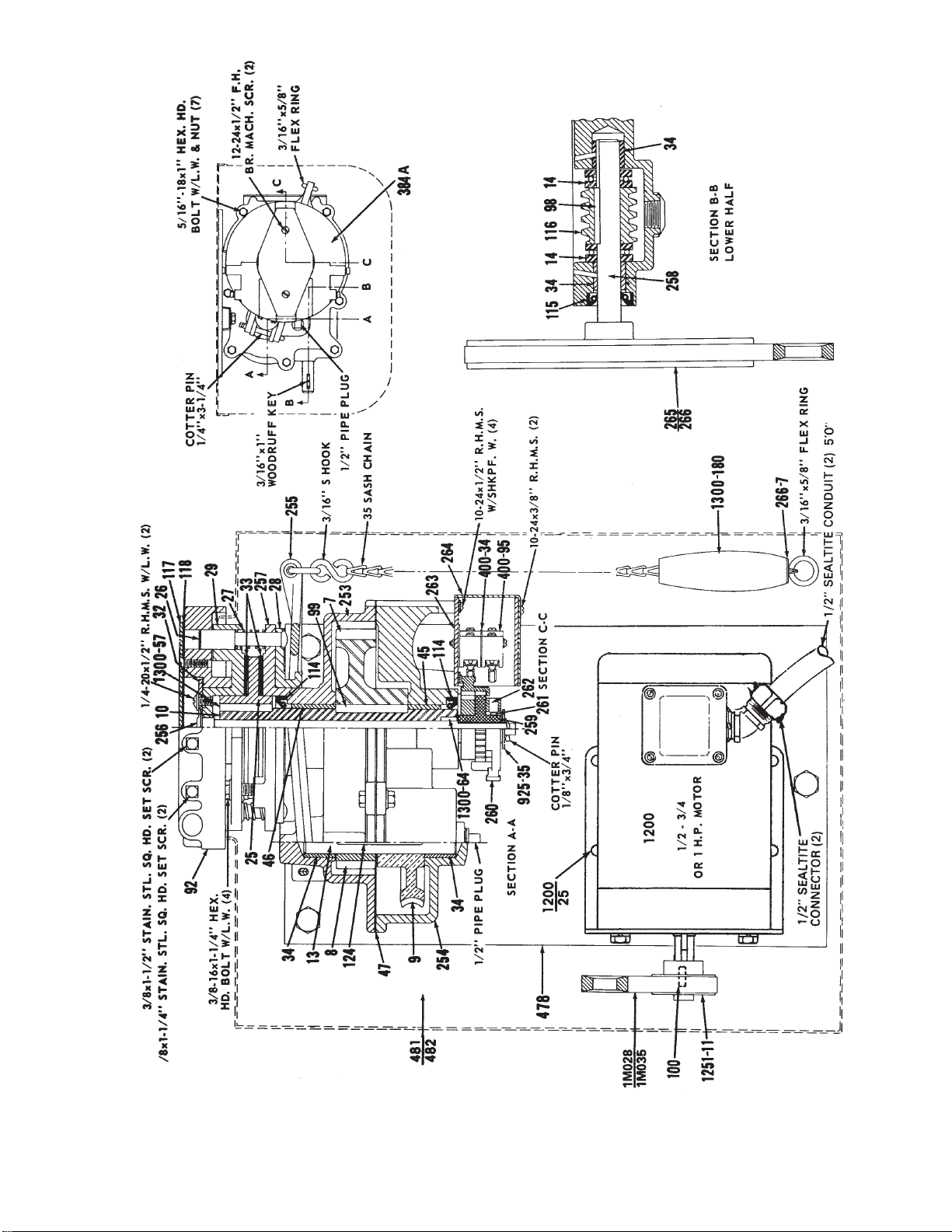
Figure 8. Illustration of Parts - Heavy Duty 1/2 - 3/4 - 1 HP Operator
Crown Industrial Operators • 213 Michelle Ct. • So. San Francisco, Ca 94080-6202
Phone: (650) 952-5150 • Fax: (650) 873-1495

FIGURE NO. PART NUMBER DESCRIPTION
9 400-34 Switch Insulator (2 per operator)
9 400-95 Snap Action Switch (2 per operator)
9 405-226 Spring (2 per operator)
9 405-2120-1 1/4" x 1-1/2" Ring
9 925-35 Washer
9 1300-64 Clutch Shaft Bushing
9 1300-180 Handle
9 1500-64 Arm Plate
9 1500-65 Top Clutch Plate
9 1500-66 Bottom Clutch Plate
9 1500-69 Shift Collar
9 1500-73 Clutch Disc (2 per operator)
9 1500-75 Pivot Pin (2 per operator)
9 1500-77 Pivot Pin (2 per operator)
9 1500-148 Arm Plate Cap
9 1500-149 Arm Plate Cap Gasket
9 1500-206A Base Assembly L.H.
9 1500-207A Base Assembly R.H.
9 1500-213 Arm Plate
9 1500-214 Clutch Spacer
8 1500-215A Clutch Assembly (Consisting of Parts: 64, 65, 66, 69, 73, 75, 77, 213, and 405-226)
8 1500-227A Top CoverAssembly L.H.
8 1500-228A Top CoverAssembly R.H.
8 1500-229A Front Cover L.H.
8 1500-230A Front Cover R.H.
8 1500-231 Motor Shim
8 1500-237A Clutch Lever Assembly
8 1500-238 Release Pivot Pin
8 1500-240 Gearmotor 230/460-60-3 R.H.
8 1500-241 Gearmotor 230/460-60-3 L.H.
8 1500-259 Switch Throw Pinion
8 1500-260 Switch Cam (2 per operator)
8 1500-261 Spring (2 per operator)
8 1500-262 Closed End Eyelet (2 per operator)
8 1500-264 Switch Cover
8 1500-385 Clutch Bolt
8 1500-389 Support Stud (4 per operator)
8 1500-390A Limit Switch Housing Assembly
PARTS LIST -- EXTRA HEAVY DUTY 1 HP OPERATOR
Crown Industrial Operators • 213 Michelle Ct. • So. San Francisco, Ca 94080-6202
Phone: (650) 952-5150 • Fax: (650) 873-1495

Figure 9. Illustration of Parts - Extra Heavy Duty 1 HP
Crown Industrial Operators • 213 Michelle Ct. • So. San Francisco, Ca 94080-6202
Phone: (650) 952-5150 • Fax: (650) 873-1495

Crown Industrial Operators
213 Michelle Court
So. San Francisco, CA 94080
Phone (650) 952-5150
Fax (650) 873-1495
website: www.crown-industrial.com
GUARANTEE
If, within a period of one year from date of shipment, any part of a CIO
Electric "Aut-o-doR" Operator is found defective due to poor materials
or workmanship, new parts will be furnished free of charge F.O.B.
manufacturer’s plant, providing the equipment has been given normal
and proper usage, lubrication, and maintenance and is still the property
of the original purchaser and/or part of the original installation. THIS
WARRANTY IS GIVEN IN LIEU OF ALL OTHER WARRANTIES,
EXPRESSED OR IMPLIED, AND THE MANUFACTURER MAKES
NO IMPLIED WARRANTY OF MERCHANTABILITY BEYOND THE
EXPRESSED TERMS HEREOF. MANUFACTURER’S LIABILITY FOR
DAMAGES, INCLUDING CONSEQUENTIAL DAMAGES RESULTING
FROM ANY SUCH DEFECTIVE PRODUCT IS STRICTLY LIMITED TO
THE DELIVERY OF NEW PARTS, AS SET FORTH ABOVE.
Operator Serial Number _______________________________ H.P. ____________________________________
Supplied on Crown Industrial Operators Order Number __________________________________________________
Power Supply ____________ Volts ___________ Hz _______________ Phase __________________________
Installed At _______________________________ Date _______________________________________________
Notes ________________________________________________________________________________________
________________________________________________________________________________________
________________________________________________________________________________________
________________________________________________________________________________________
________________________________________________________________________________________
MAINTENANCE INFORMATION
(To Be Filled Out By User)
G-993-R3
Table of contents
Other CROWN INDUSTRIAL Gate Opener manuals


