manuals.online logo
Brands
  1. Home
  2. •
  3. Brands
  4. •
  5. Crown
  6. •
  7. Microphone
  8. •
  9. Crown PCC-170SWO User manual

Crown PCC-170SWO User manual

POLAR
PATTERN
Specifications
Element: Electret condenser.
Frequency response (typical): 40 Hz to 20,000 Hz at
30 degrees incidence to surface. See Fig. 1.
Polar pattern: Half-supercardioid (supercardioid in
the hemisphere above the primary boundary). See
Figs. 2 and 3.
Impedance: 150 ohms, balanced. (Recommended
load impedance 1000 ohms or greater.)
Open-circuit sensitivity: 22 mV/Pa* (–33 dB re
1 V/Pa*).
Power sensitivity: –30.5 dB re 1 milliwatt/Pa*.
–125 dBm EIA rating.
Equivalent noise level (self noise): 22 dB SPL typical
(0 dB = .0002 dyne/cm2), A-weighted.
S/N ratio: 72 dB at 94 dB SPL.
Maximum SPL: 120 dB SPL produces 3% THD.
Polarity: Positive pressure on the diaphragm produces
positive voltage on pin 2 with respect to pin 3.
Operating voltage: Phantom power: 24 to 48 volts DC
positive on pins 2 and 3 with respect to pin 1.
Current drain: 6.8 mA nominal.
Cable: 15-foot, black, integral to microphone, unter-
minated.
Off-attenuation: 70 dB at 1 kHz.
Maximum voltage and current which may be applied
to remote sensing contact-closure leads: 350 V,
200 mA. Small voltages are recommended; large
voltage changes may induce noise in audio output.
On-resistance: 7 to 10 ohms with the included 15-foot
cable.
Cable wiring:
Shield: Audio shield.
Green: Audio in-polarity.
White: Audio opposite-polarity.
Red: Remote contact-closure sensing, +DC.
Black: Remote contact-closure sensing, –DC.
Operating temperature range: –10° to +50° C, or
+14° to +122° F.
Materials: High-impact molded plastic and steel mesh
grille.
Finish: Satin black.
Net weight: 6 oz. (170 g).
Dimensions: See Fig. 4.
Optional accessories: Crown PH-1A phantom
Fig. 1
Fig. 2
Fig. 3
Frequency Response
Vertical Plane Polar Response
*1 pascal = 10 dynes/cm2= 10 microbars = 94 dB SPL.
Horizontal Plane Polar Response
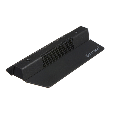
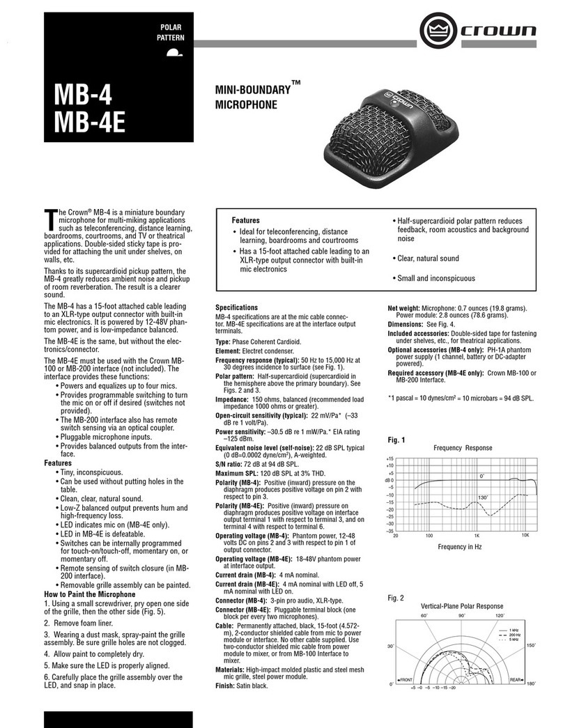
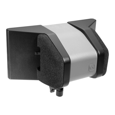
The Crown®PCC-170SWO is a surface-
mounted supercardioid microphone for
distance learning or similar applications.
The user can turn the mic on and off by press-
ing a membrane switch on the mic. A pair
of extra leads in the mic cable allow isolated
remote sensing of the microphone switch clo-
sure. In a typical distance-learning application,
a video camera would track to the person who
switched on the microphone.
The mic includes a bass-tilt switch, which lets
the user tailor the low-end response for par-
ticular applications. A high-frequency adjust is
also provided.
The membrane switch can be configured for
touch on/off, momentary on, or momentary off
operation. This configuration is set by a bot-
tom-mounted DIP switch. A high-intensity LED
lights when the unit is on.
The mic can be set to be always on. In this
mode, the switch only activates the remote
sensing and LED. This is useful when using an
external gated mixer (automatic mixer).
Remote sensing is done by a patented opto-
coupled MOS switching circuit. At the remote-
sensing leads, the resistance goes low when
the mic is on. The microphone is attenuated 70
dB when the switch is off.
How to Set the Bass Tilt Switch
On the bottom of the microphone is a BASS-
TILT switch with three positions: FLAT, CUT,
and BOOST. It adjusts the low-frequency re-
sponse as shown in Fig. 1.
• The FLAT position provides a flat low-fre-
quency response, (normal operation). The mic
is shipped from the factory in the flat position.
• The CUT position rolls off the bass, useful in
noisy or boomy surroundings.
• The BOOST position boosts the bass for a
more natural sound when the mic is used on a
small surface such as a lectern.
You can also adjust the high-frequency re-
sponse. Insert a small screwdriver into the hole
labeled “HF ADJ” on the bottom of the mic.
How to Configure the Membrane Switch
The membrane switch can be programmed to
work three ways:
1. Touch on/off. Touch the switch to turn on
the mic; touch it again to turn off the mic.
2. Momentary on. Touch and hold the switch
to momentarily turn on the mic. Release the
switch to turn the mic back off.
3. Momentary off. Touch and hold the switch
to momentarily turn off the mic. Release the
switch to turn the mic back on. This option
Features
• Ideal for distance learning applications
• Programmable on/off switch
• Extra leads in mic cable allow remote
sensing of mic switch closure
• Half-supercardioid polar pattern reduces
pickup of muddy-sounding room acoustics
• Bass-tilt switch
• Adjustable high-frequency response
PCC®-170SWO
PHASE COHERENT
CARDIOID®MICROPHONE
power supply (one channel, battery or AC-adapter
powered).
Crown International, Inc.
1718 W. Mishawaka Rd.
Elkhart, IN 46517-9439
TEL: 574-294-8000
FAX: 574-294-8FAX
www.crownaudio.com
serves as a cough button or privacy button.
After choosing the option you prefer, set the
DIP switches according to the label on the
bottom of the microphone (see Fig. 5). The LED
in the microphone housing will light when the
mic is on.
If you want the mic to be continuously on (so
you can gate it on and off externally), set the
DIP switch to “DISABLE MIC GATING.”
Installation
Typical placement for each microphone is at
arm’s length from the user. Either place one
microphone in front of each person or one
between every two people. The front of the
microphone is indicated by an arrow on the
bottom of the base plate.
If the microphone is used on a lectern, place it
on an open surface, not in a cavity. Otherwise
the frequency response and polar pattern will
be degraded.
Solder the shield, green and white leads to an
XLR type connector, shield to pin 1, green to 2,
white to 3. Plug this connector into the input of
a phantom-power supply such as a Crown PH-
1A. Connect the output to a mixer mic input.
Or if your mixer has phantom power built in,
connect each mic cable directly to a mixer mic
input.
PCC-170SWO
Specifications subject to change without prior
notice. Latest information available at www.crown-
audio.com. Crown, Crown Audio, PCC and Phase
Coherent Cardioid are registered trademarks of
Crown International, Inc.
©2006 Crown Audio®, Inc.
Sample circuit for remote sensing.
10/06 101793-8
3.4"
8.6 cm
.900"
2.3 c
m
4.84"
12.3 cm
TOUCH
Fig. 6
Fig. 4 Dimensions
Fig. 5
Fig. 7
Dimensions are to outside of plastic housing
The PCC includes two keyhole slots in its base
to accept mounting screws. To screw the PCC
to a table top, follow this procedure:
1. Punch out the keyholes marked on the label
underneath the base plate (use a razor blade,
small screwdriver, etc.).
2. Using the template (Fig. 6), mark the loca-
tion of two holes in the table where you want to
mount the mic. These holes are 1.6-inch (4.064
cm) apart, center-to-center.
3. Screw two #8 woodscrews (.270” dia. head)
into the table at the locations you marked.
4. Loosen the screws enough to receive the mic
and to hold it with a friction fit.
Operation
Press near the center of the switch. The micro-
phone will switch on or off according to how
you set the DIP switches. When the mic is on,
the LED in the housing is lit.
If you set the DIP switch to “DISABLE MIC
GATING,” the mic is always on. Pressing the
switch will light the LED and activate remote
sensing.
The contact-closure leads (red and black) pro-
vide remote sensing of mic attenuation. Switch
closed (low resistance) is mic ON. Switch open
(high resistance) is mic OFF.
To detect when the mic is on, apply a small
voltage to the remote sensing leads (Fig. 7).
Apply +DC to the red lead and -DC to the black
lead. Large voltage and current may induce
noise into the audio output. Maximum switch
voltage and current are 350 V, 200 mA. On-
resistance is 7 to 10 ohms with the included
15-foot cable.
Warranty
Crown professional microphones are guaran-
teed against malfunction for a period of three
years from date of original purchase. Please
refer to the enclosed full warranty sheet for
more detail.
Service
If the microphone does not function properly,
replace or repair mic cables and connectors,
check the power supply. If service is required,
return the microphone in its original packag-
ing to: Crown Factory Service, 1718 W.
Mishawaka Road, Elkhart, IN 46517-9439.
A Service Return Authorization (SRA) is re-
quired for product being sent to the factory for
service. An SRA can be completed on line at
www.crownaudio.com/support/factserv.htm.
For further assistance or technical support call
800-342-6939.
MIC RL 2K
9V
RED 5
+DC
BLK
–DC
AUDIO +
AUDIO –
GRN
WHT
1
4
2
3
SHIELD

Other Crown Microphone manuals

Crown PZM-6D User manual

Crown

Crown PZM-6D User manual

Crown MINI-BOUNDARY MB-2 User manual

Crown

Crown MINI-BOUNDARY MB-2 User manual

Crown MINI-BOUNDARY MB-4 User manual

Crown

Crown MINI-BOUNDARY MB-4 User manual

Crown CM-312AE User manual

Crown

Crown CM-312AE User manual

Crown DIFFEROID CM-311A User manual

Crown

Crown DIFFEROID CM-311A User manual

Crown CM-312AHS User manual

Crown

Crown CM-312AHS User manual

Crown PZM-6F User manual

Crown

Crown PZM-6F User manual

Crown PZM-185 User manual

Crown

Crown PZM-185 User manual

Crown PCC-170 User manual

Crown

Crown PCC-170 User manual

Crown PZM-185 User manual

Crown

Crown PZM-185 User manual

Crown PZM-10 User guide

Crown

Crown PZM-10 User guide

Crown PZM-30D User manual

Crown

Crown PZM-30D User manual

Crown CM-700 User manual

Crown

Crown CM-700 User manual

Crown CM-312A User manual

Crown

Crown CM-312A User manual

Crown LM-200A User manual

Crown

Crown LM-200A User manual

Crown PCC-170SWO User manual

Crown

Crown PCC-170SWO User manual

Crown PCC-130SW User manual

Crown

Crown PCC-130SW User manual

Crown CM-200A User manual

Crown

Crown CM-200A User manual

Crown PZM-180 User manual

Crown

Crown PZM-180 User manual

Crown PZM-2LV User manual

Crown

Crown PZM-2LV User manual

Crown PCC-170 User manual

Crown

Crown PCC-170 User manual

Crown LM-301A User manual

Crown

Crown LM-301A User manual

Crown LM-201 User manual

Crown

Crown LM-201 User manual

Crown PCC-160 User manual

Crown

Crown PCC-160 User manual

Popular Microphone manuals by other brands

Monacor DM-3 manual

Monacor

Monacor DM-3 manual

Neumann Sm 23c Specification sheet

Neumann

Neumann Sm 23c Specification sheet

Andrea SG-110M quick start guide

Andrea

Andrea SG-110M quick start guide

Samson DE50x owner's manual

Samson

Samson DE50x owner's manual

Avermedia Live Streamer MIC 133 quick guide

Avermedia

Avermedia Live Streamer MIC 133 quick guide

Monacor ECM-300DT manual

Monacor

Monacor ECM-300DT manual

Beyerdynamic TG-X 930 manual

Beyerdynamic

Beyerdynamic TG-X 930 manual

Shure WL183 user guide

Shure

Shure WL183 user guide

AKG C 414 B/ULS Specifications

AKG

AKG C 414 B/ULS Specifications

Monkey Banana Hapa user manual

Monkey Banana

Monkey Banana Hapa user manual

Audio Technica AT8024 quick start guide

Audio Technica

Audio Technica AT8024 quick start guide

Monacor img Stage Line HSE-150A/SK operating instructions

Monacor

Monacor img Stage Line HSE-150A/SK operating instructions

Chiayo NH-3100 Operation manual

Chiayo

Chiayo NH-3100 Operation manual

Mobility Sound BTH-600R manual

Mobility Sound

Mobility Sound BTH-600R manual

Audix M1280B quick start guide

Audix

Audix M1280B quick start guide

AEA R84 series owner's manual

AEA

AEA R84 series owner's manual

Saramonic Vmic Pro manual

Saramonic

Saramonic Vmic Pro manual

AKG D 5 User instructions

AKG

AKG D 5 User instructions

manuals.online logo
manuals.online logoBrands
  • About & Mission
  • Contact us
  • Privacy Policy
  • Terms and Conditions

Copyright 2025 Manuals.Online. All Rights Reserved.